EP2555672B1 - Wegwerfbarer elektroden-patch - Google Patents
Wegwerfbarer elektroden-patch Download PDFInfo
- Publication number
- EP2555672B1 EP2555672B1 EP10717882.4A EP10717882A EP2555672B1 EP 2555672 B1 EP2555672 B1 EP 2555672B1 EP 10717882 A EP10717882 A EP 10717882A EP 2555672 B1 EP2555672 B1 EP 2555672B1
- Authority
- EP
- European Patent Office
- Prior art keywords
- electrode
- body part
- patch according
- adhesive
- electrode patch
- Prior art date
- Legal status (The legal status is an assumption and is not a legal conclusion. Google has not performed a legal analysis and makes no representation as to the accuracy of the status listed.)
- Active
Links
Images
Classifications
-
- A—HUMAN NECESSITIES
- A61—MEDICAL OR VETERINARY SCIENCE; HYGIENE
- A61B—DIAGNOSIS; SURGERY; IDENTIFICATION
- A61B5/00—Measuring for diagnostic purposes; Identification of persons
- A61B5/24—Detecting, measuring or recording bioelectric or biomagnetic signals of the body or parts thereof
- A61B5/25—Bioelectric electrodes therefor
- A61B5/251—Means for maintaining electrode contact with the body
- A61B5/257—Means for maintaining electrode contact with the body using adhesive means, e.g. adhesive pads or tapes
-
- A—HUMAN NECESSITIES
- A61—MEDICAL OR VETERINARY SCIENCE; HYGIENE
- A61B—DIAGNOSIS; SURGERY; IDENTIFICATION
- A61B5/00—Measuring for diagnostic purposes; Identification of persons
- A61B5/24—Detecting, measuring or recording bioelectric or biomagnetic signals of the body or parts thereof
- A61B5/25—Bioelectric electrodes therefor
- A61B5/279—Bioelectric electrodes therefor specially adapted for particular uses
- A61B5/28—Bioelectric electrodes therefor specially adapted for particular uses for electrocardiography [ECG]
- A61B5/282—Holders for multiple electrodes
-
- A—HUMAN NECESSITIES
- A61—MEDICAL OR VETERINARY SCIENCE; HYGIENE
- A61B—DIAGNOSIS; SURGERY; IDENTIFICATION
- A61B5/00—Measuring for diagnostic purposes; Identification of persons
- A61B5/24—Detecting, measuring or recording bioelectric or biomagnetic signals of the body or parts thereof
- A61B5/25—Bioelectric electrodes therefor
- A61B5/279—Bioelectric electrodes therefor specially adapted for particular uses
- A61B5/296—Bioelectric electrodes therefor specially adapted for particular uses for electromyography [EMG]
Definitions
- the invention relates to a disposable electrode patch for medical purposes, particularly to be fixed onto the skin of a body part of a patient.
- Medical electrodes are needed in many applications, e.g. for measurement of electrical activity in the brain (EEG), the heart (ECG), or the muscles (EMG).
- Medical electrodes may be used for measuring, e.g., electric current, potential/voltage, skin conductance, and skin resistance. Certain medical electrodes may also be used for supplying electrical energy into the patient, e.g. in the case of defibrillators, electroconvulsive therapy and other therapy methods.
- Medical electrodes are also used in the fields of electrophysiology and neuroscience.
- a particular class of equipment and methods utilize measurement of skin conductance for assessing the state of the autonomous nervous system of a patient, such as a sedated patient, e.g. for detecting pain or awakening during anaesthesia.
- WO-03/094726 is an example of an apparatus and a method for monitoring the autonomous nervous system of a sedated patient, wherein the skin conductance, measured by use of electrodes placed on the skin of the patient, is measured. Signals indicating pain/discomfort in the patient and awakening in the patient are derived from the skin conductance measurements.
- An object of the invention is to provide an improved electrode patch which may be advantageously used with infants or other persons/patients with sensible skin, in particular in humid environments.
- a patch according to the preamble of claim 1 is known from document US2007/0100219 .
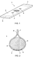
- Figure 1 is a schematic block diagram illustrating a disposable electrode patch in accordance with the invention, in a state before it is attached to a body part of a patient.
- the electrode patch 1 comprises a first conductive electrode 2, a second conductive electrode 3 and a third conductive electrode 4, all arranged in a flexible, elongated, non-conductive substrate.
- the substrate has a first surface 5 and a second, opposite surface (not visible on fig. 1 ).
- the substrate 5 has an elongated shape, e.g. a substantially rectangular shape as illustrated.
- the shape may be rectangular with rounded corners, oval, or any other suitable shape.
- a first adhesive material is disposed on a first adhesive area 6 at a first end of the first surface.
- a second adhesive material is disposed on a second adhesive area 7 at a second end of the first surface.
- a number of electrodes are arranged between the first and second adhesive areas on the first surface of the substrate.
- the electrodes may be of the type known as Ag/AgCl electrodes, although other types may alternatively be used.
- Such an arrangement allows the electrode patch to be folded around a body part in such a way that the electrodes on the first surface make contact with the skin of the body part. Also, the first and second adhesive areas of the first surface are allowed to be pinched together to form a stable assembly surrounding the body part. This is further illustrated in figure 2 .
- the arrangement of attaching the electrode patch ensures that the electrodes do not suffer from excessive, undesired movement, which might lead to artefacts in the resulting measurements.
- the attachment of two adhesive patch areas together makes a firm and stable connection even in a humid environment such as, e.g., inside an incubator.
- the area of the first surface, except from the first and second adhesive areas, may be non-adhesive. This will reduce the adhesive's possible unfavourable or irritating effect on the skin of the body part.
- the substrate may comprise a foam material or another flexible material.
- the electrodes may be covered with a layer of an electrode paste.
- the electrode paste may be prepared as a part of the disposable electrode patch. Alternatively, the electrode paste may be applied before use.
- the first electrode 2 is a counter current electrode
- the second electrode 3 is a measuring electrode
- the third electrode 4 is a reference voltage electrode.
- the first electrode 1 may be electrically connected to a first connecting line (not shown)
- the second electrode 2 may be electrically connected to a second connecting line (not shown).
- the third electrode 4 may be electrically connected to a third connecting line (not shown).
- electrodes 2, 3, 4 may vary in accordance with the intended use of the electrode and other circumstances. In an aspect, there are three electrodes in the electrode patch.
- Figure 2 is a schematic diagram illustrating the medical electrode patch attached to a body part 8 such as the plantar side of an infant's foot. Please refer to the description of figure 1 for a detailed description of those elements of figure 2 which are identical to (and have the same reference numerals as) those illustrated in figure 1 .
- the body part 8 may be a body part of an infant, including a preterm or a neonatal infant.
- the medical electrode patch may be used with body parts of any human or animal individual where it is necessary or desired to attach a medical electrode patch to the skin.
- the body part 8 may be the plantar side of a foot or heel, or the palm of a hand, or any other suitable body part.
- the electrode patch is allowed to be folded around the body part 8 in such a way that the electrodes 2, 3, 4 on the first surface make contact with the skin of the body part 8. Further, the first and second adhesive areas of the first surface are pinched (or pressed) together to form a tight and stable assembly surrounding the body part 8.
- the medical electrode patch as disclosed in any of the above figures may e.g. be used in an arrangement for measuring skin conductance, e.g. of a patient.
- the electrode patch 1 may be placed attached to an area of the skin on a body part of the patient, in such a way that is described above with reference to figure 2 , for the purpose of measuring the skin's conductance at that area.
- the first electrode 2 may a counter current electrode
- the second electrode 3 may be a measuring electrode
- the third electrode 4 may be a reference voltage electrode, all arranged in the patch 5, which is placed on the skin area and attached by the attachment means described herein.
- the electrode patch 1 and its connected external equipment may ensure a constant application of voltage over the stratum corneum (the surface layer of the skin) under the measuring electrode.
- the resulting current in a closed circuit between the measuring electrode 3 and the counter current electrode 2 may be measured by means of a measurement converter (not shown), connected between the counter current electrode 2 and the measuring electrode 3.
- the measurement converter may comprise a current to voltage converter, such as a transresistance amplifier or simply a resistance, which converts the current from the measuring electrode 3 to a voltage.
- the electrode patch disclosed herein may also be used in an arrangement for monitoring the autonomous nervous system of a patient. Such monitoring may be non-diagnostic.
- the measuring equipment is connected to a processing device configured for monitoring the autonomous nervous system of the patient, based on measurements of the skin conductance.
- a processing device configured for monitoring the autonomous nervous system of the patient, based on measurements of the skin conductance.
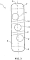
- Figure 3 is a schematic block diagram illustrating an embodiment of an electrode patch before it is attached to a body part of a patient.
- the electrode patch 1 comprises a first conductive electrode 2, a second conductive electrode 3 and a third conductive electrode 4, all arranged in a flexible, elongated, non-conductive substrate.
- the substrate has a first surface 5 and a second, opposite surface (not visible on fig. 3 ).
- the electrodes comprise a counter current electrode, a measuring electrode and a reference voltage electrode. More specifically, the first electrode 2 is a counter current electrode, the second electrode 3 is a measuring electrode, and the third electrode 4 is a reference voltage electrode. Electrical connections may be provided in the same way as in the embodiment described above with reference to figure 1 .
- the substrate 5 has an elongated shape, e.g. a substantially rectangular shape with rounded corners, as illustrated. Other shapes are possible, as described earlier.
- a first adhesive material is disposed on a first adhesive area 6 at a first end of the first surface and, a second adhesive material is disposed on a second adhesive area 7 at a second end of the first surface.
- the counter current electrode 2 and the reference voltage electrode 4 are arranged with their centers on opposite sides of a line 9 which is parallel with the elongated substrate and which intersects a center of the measuring electrode 3.
- the line 9 does not need to be realized as a physical line. Rather, this line has been included in the present specification for the purpose of defining the relative positions of the various electrodes in the electrode patch.
- the counter current electrode 2, the measuring electrode 3 and the reference voltage electrode 4 may have a substantially circular shape, as shown. Other shapes are possible.
- the above-mentioned line which is parallel with the elongated substrate, and which intersects the center of the measuring electrode 3, may also intersect an area of each of the counter current electrode 2 and the reference voltage electrode 4, as illustrated in figure 3 .
- the line which is parallel with the elongated substrate, and which intersects the center of the measuring electrode does not intersect any one of the counter current electrode 2 or the reference voltage electrode 4, or the line may intersect only one of the counter current electrode 2 and the reference voltage electrode 4.
- the areas of the counter current electrode 2, the measuring electrode 3 and the reference voltage electrode 4 are the same or substantially the same. In other embodiments, the areas may be different. For instance, in the embodiment of figure 1 , the measuring electrode 3 is substantially larger than the counter current electrode 2 and the reference voltage electrode 4.
- Figure 3 further shows a slanted strip area 10 between the reference voltage electrode 4 and the measuring electrode 3, and a similar slanted strip area 11 between the measuring electrode 3 and the counter current electrode 2.
- electrode paste is applied not only to the electrodes 2, 3, and 4, but also to the rhomb- or parallelogram-shaped areas surrounding each electrode 2, 3, 4. However, in an aspect, electrode paste is not applied to the slanted strips 10, 11. Also, in an aspect, electrode paste is not applied to the adhesive areas 6 and 7.
- electrode paste may be pre-applied on the entire surface 5 of the patch except from the adhesive areas 6 and 7 and the slanted strips 10, 11.
- Area of the central electrode 3 between 100 mm 2 and 400 mm 2 , more specifically, between 200 mm 2 and 300 mm 2 , e.g. about 260 mm 2 .
- Area of the outer electrodes 2, 4 between 30 mm 2 and 250 mm 2 , more specifically, between 70 mm 2 and 150 mm 2 , e.g. about 100 mm 2 .
- the central electrode 3 may have the same or approximately the same area as each of the outer electrodes.
- Distance between electrodes between 0.2 mm and 3 mm, more specifically, between 0.5 mm and 1.2 mm, e.g. about 0.7 mm.
- the distance between electrodes i.e., distance between outer edge of subsequent electrodes
- the distance between electrodes may be between 2 mm and 8 mm, more specifically, between 4 and 6 mm, e.g., about 5 mm.
- Total length of patch between 40 mm and 120 mm, more specifically, between between 60 mm and 100 mm,, e.g. about 80 mm.
- Total width of patch between 10 mm and 30 mm, more specifically, between 15 mm and 25 mm, e.g. about 20 mm.
- Thickness of patch between 0.5 mm and 2 mm, more specifically, between 0.8 mm and 1.5 mm, e.g. about 1.0 mm.
- Length of first 6 and second 7 adhesive areas (measured in longitudinal direction of the elongated patch): between 5 mm and 20 mm, more specifically, between 8 mm and 15 mm, e.g. about 10 mm.
- Length of slanted strip area between 2 and 6 mm, more specifically, between 3 and 5 mm, e.g. about 4 mm.
- An electrode paste useful for application with the electrode patch may, as an example, have the following composition: 6 g hydroxyethylcellulose 700, 0.58 g NaCl, 0.1 g methylparahydroxybenzene, 0.1 g propylparahydroxybenzene, 2 g alcohol 96%, and purified water up to 100 g. Electrode pastes with other compositions may alternatively be used.
Landscapes
- Health & Medical Sciences (AREA)
- Life Sciences & Earth Sciences (AREA)
- Medical Informatics (AREA)
- Biophysics (AREA)
- Pathology (AREA)
- Engineering & Computer Science (AREA)
- Biomedical Technology (AREA)
- Heart & Thoracic Surgery (AREA)
- Physics & Mathematics (AREA)
- Molecular Biology (AREA)
- Surgery (AREA)
- Animal Behavior & Ethology (AREA)
- General Health & Medical Sciences (AREA)
- Public Health (AREA)
- Veterinary Medicine (AREA)
- Cardiology (AREA)
- Measurement And Recording Of Electrical Phenomena And Electrical Characteristics Of The Living Body (AREA)
- Electrotherapy Devices (AREA)
Claims (11)
- Wegwerfbarer Elektroden-Patch für medizinische Zwecke, umfassend:ein flexibles, lang gestrecktes Substrat mit einer ersten und einer zweiten Oberfläche,einen ersten Klebstoff, der auf einem ersten Klebebereich an einem ersten Ende der ersten Oberfläche angeordnet ist, undeinen zweiten Klebstoff, der auf einem zweiten Klebebereich an einem zweiten Ende der ersten Oberfläche angeordnet ist, undmehrere Elektroden, die zwischen dem ersten und zweiten Klebebereich auf der ersten Oberfläche des Substrats angeordnet sind, wodurch gestattet wird, dass der Elektroden-Patch derart um einen Körperteil herum gefaltet wird, dass die Elektroden auf der ersten Oberfläche mit der Haut des Körperteils in Kontakt kommen, und ferner gestattet wird, dass der erste und zweite Klebebereich der ersten Oberfläche zusammengedrückt werden, um eine den Körperteil umgebende stabile Anordnung auszubilden,dadurch gekennzeichnet, dassdie Elektroden eine Gegenstromelektrode, eine Messelektrode und eine Referenzspannungselektrode umfassen, undwobei die Gegenstromelektrode und die Referenzspannungselektrode mit ihren Mitten auf gegenüberliegenden Seiten einer Linie angeordnet sind, die parallel zu dem lang gestreckten Substrat ist und eine Mitte der Messelektrode schneidet.
- Wegwerfbarer Elektroden-Patch nach Anspruch 1,
wobei das Substrat einen Schaumstoff umfasst. - Wegwerfbarer Elektroden-Patch nach einem der Ansprüche 1-2,
wobei die Elektroden mit einer Deckschicht aus einer Elektrodenpaste hergestellt sind. - Wegwerfbarer Elektroden-Patch nach einem der Ansprüche 1-3,
wobei der Bereich der ersten Oberfläche mit Ausnahme des ersten und zweiten Klebebereichs nichtklebend ist. - Wegwerfbarer Elektroden-Patch nach einem der Ansprüche 1-4,
wobei die Anzahl der Elektroden drei beträgt. - Wegwerfbarer Elektroden-Patch nach Anspruch 5,
wobei die Gegenstromelektrode, die Messelektrode und die Referenzspannungselektrode jeweils im Wesentlichen eine Kreisform aufweisen. - Wegwerfbarer Elektroden-Patch nach Anspruch 6,
wobei die Linie, die parallel zu dem lang gestreckten Substrat ist und die Mitte der Messelektrode schneidet, auch einen Bereich sowohl der Gegenstromelektrode als auch der Referenzspannungselektrode schneidet. - Wegwerfbarer Elektroden-Patch nach einem der Ansprüche 1-7,
wobei der Körperteil ein Körperteil eines Säuglings, darunter eines frühgeborenen oder eines neugeborenen Säuglings, ist. - Wegwerfbarer Elektroden-Patch nach einem der Ansprüche 1-8,
wobei der Körperteil die Plantarseite eines Fußes oder einer Ferse oder die Innenfläche einer Hand ist. - Verwendung eines Elektroden-Patches nach einem der Ansprüche 1-9
in einer Anordnung zum Messen der Hautleitfähigkeit. - Verwendung eines Elektroden-Patches nach einem der Ansprüche 1-9
in einer Anordnung zum Überwachen des vegetativen Nervensystems eines Patienten.
Applications Claiming Priority (1)
| Application Number | Priority Date | Filing Date | Title |
|---|---|---|---|
| PCT/NO2010/000130 WO2011126376A1 (en) | 2010-04-08 | 2010-04-08 | Disposable electrode patch |
Publications (2)
| Publication Number | Publication Date |
|---|---|
| EP2555672A1 EP2555672A1 (de) | 2013-02-13 |
| EP2555672B1 true EP2555672B1 (de) | 2018-07-11 |
Family
ID=44763125
Family Applications (1)
| Application Number | Title | Priority Date | Filing Date |
|---|---|---|---|
| EP10717882.4A Active EP2555672B1 (de) | 2010-04-08 | 2010-04-08 | Wegwerfbarer elektroden-patch |
Country Status (7)
| Country | Link |
|---|---|
| US (1) | US8750958B2 (de) |
| EP (1) | EP2555672B1 (de) |
| JP (1) | JP5669927B2 (de) |
| AU (1) | AU2010350780A1 (de) |
| CA (1) | CA2794409C (de) |
| RU (1) | RU2530562C2 (de) |
| WO (1) | WO2011126376A1 (de) |
Families Citing this family (14)
| Publication number | Priority date | Publication date | Assignee | Title |
|---|---|---|---|---|
| CN103462601B (zh) * | 2013-09-24 | 2016-06-15 | 深圳先进技术研究院 | 医用电极贴及其制备方法 |
| US9314203B2 (en) * | 2013-10-15 | 2016-04-19 | Nemo Healthcare B.V. | Sensor for foetal monitoring |
| USD752764S1 (en) | 2013-11-04 | 2016-03-29 | Nemo Healthcare B.V. | Electrode patch |
| FI20145542A7 (fi) * | 2014-06-12 | 2015-12-13 | Bittium Biosignals Oy | Elektrodipanta bioelektrisen signaalin mittaamiseksi |
| TW201622668A (zh) * | 2014-12-16 | 2016-07-01 | 準訊生醫股份有限公司 | 長效型貼片敷料結構 |
| RU2719953C2 (ru) * | 2015-06-30 | 2020-04-23 | Санстар Суисс Са | Одноразовая адгезивная подложка, выполненная с возможностью расположения на медицинском устройстве |
| US10390759B2 (en) | 2016-02-25 | 2019-08-27 | Welch Allyn, Inc. | Physical assessment parameter measuring device |
| RU174400U1 (ru) * | 2017-04-10 | 2017-10-11 | Общество с ограниченной ответственностью "Медицинские Компьютерные Системы" | Электродный датчик для ЭКГ-исследований |
| JP7017426B2 (ja) * | 2017-04-28 | 2022-02-08 | 日東電工株式会社 | 生体センサ用積層体および生体センサ用積層体の製造方法 |
| JP6997533B2 (ja) | 2017-04-28 | 2022-01-17 | 日東電工株式会社 | 生体センサ用シート |
| WO2018198571A1 (ja) * | 2017-04-28 | 2018-11-01 | 日東電工株式会社 | 生体センサ用積層体および生体センサ用積層体の製造方法 |
| USD898202S1 (en) * | 2017-11-12 | 2020-10-06 | Dms-Service Llc | Patch with electrode array |
| WO2021011588A1 (en) | 2019-07-15 | 2021-01-21 | Massachusetts Institute Of Technology | Tracking nociception under anesthesia using a multimodal metric |
| US12622622B2 (en) | 2023-03-01 | 2026-05-12 | Synchneuro, Inc. | Blood glucose states based on sensed brain activity |
Family Cites Families (17)
| Publication number | Priority date | Publication date | Assignee | Title |
|---|---|---|---|---|
| SU211728A1 (ru) * | 1966-12-27 | 1975-10-26 | Самостоятельное конструкторско-технологическое бюро биологического и физиологического приборостроения Министерства здравоохранения СССР | Эластичный электрод дл наложени на кожу |
| DE2748583A1 (de) * | 1977-07-18 | 1979-02-01 | Mills | Elektrokardiographische vorrichtung |
| US5170786A (en) * | 1990-09-28 | 1992-12-15 | Novametrix Medical Systems, Inc. | Reusable probe system |
| JPH07172040A (ja) | 1993-12-17 | 1995-07-11 | New Oji Paper Co Ltd | インクジェット磁気複合記録用シート |
| US5579447A (en) | 1994-11-25 | 1996-11-26 | Xerox Corporation | System for developing and displaying a representation of a total estimated time to print a job |
| JPH0919420A (ja) * | 1995-07-07 | 1997-01-21 | Omron Corp | 生理状態判定方法及び生理状態判定装置 |
| JP2798069B2 (ja) * | 1996-09-05 | 1998-09-17 | オムロン株式会社 | 皮膚インピーダンス入力装置 |
| IL124964A (en) * | 1998-06-17 | 2002-02-10 | Nimeda Ltd | Method for disclosing a physiological indication and a non-invasive diagnostic physiological monitoring system for use therewith |
| NO313534B1 (no) * | 1999-06-01 | 2002-10-21 | Hanne Storm | Apparat og fremgangsmåte for overvåkning og fremgangsmåte for styring av et varselsignal |
| US6865409B2 (en) * | 2001-11-07 | 2005-03-08 | Kinesense, Inc. | Surface electromyographic electrode assembly |
| NO317897B1 (no) * | 2002-05-08 | 2004-12-27 | Hanne Storm | Apparat og fremgangsmate for a overvake det autonome nervesystemet hos en sedert pasient. |
| JP2004024769A (ja) * | 2002-06-28 | 2004-01-29 | Tokyo Metropolis | 前腕の動作に伴う筋活動の測定方法及びその装置 |
| JP2004057704A (ja) * | 2002-07-31 | 2004-02-26 | Ntt Docomo Inc | 電極装置 |
| USD511450S1 (en) * | 2003-03-21 | 2005-11-15 | 3M Innovative Properties Company | Self-engaging bundling strap provided with machine readable code |
| SE0302746D0 (sv) * | 2003-10-17 | 2003-10-17 | Uppsala Laekarkonsult Ab | Multielectrode |
| US7499739B2 (en) * | 2005-10-27 | 2009-03-03 | Smiths Medical Pm, Inc. | Single use pulse oximeter |
| KR101213157B1 (ko) * | 2006-06-09 | 2012-12-17 | 삼성전자주식회사 | 피부 임피던스 측정 센서 |
-
2010
- 2010-04-08 JP JP2013503708A patent/JP5669927B2/ja active Active
- 2010-04-08 WO PCT/NO2010/000130 patent/WO2011126376A1/en not_active Ceased
- 2010-04-08 CA CA2794409A patent/CA2794409C/en active Active
- 2010-04-08 RU RU2012146450/14A patent/RU2530562C2/ru active
- 2010-04-08 US US13/637,653 patent/US8750958B2/en active Active
- 2010-04-08 EP EP10717882.4A patent/EP2555672B1/de active Active
- 2010-04-08 AU AU2010350780A patent/AU2010350780A1/en not_active Abandoned
Non-Patent Citations (1)
| Title |
|---|
| None * |
Also Published As
| Publication number | Publication date |
|---|---|
| US20130018249A1 (en) | 2013-01-17 |
| AU2010350780A2 (en) | 2012-12-06 |
| JP2013523313A (ja) | 2013-06-17 |
| CA2794409C (en) | 2019-03-12 |
| RU2530562C2 (ru) | 2014-10-10 |
| AU2010350780A1 (en) | 2012-11-29 |
| US8750958B2 (en) | 2014-06-10 |
| EP2555672A1 (de) | 2013-02-13 |
| JP5669927B2 (ja) | 2015-02-18 |
| CA2794409A1 (en) | 2011-10-13 |
| WO2011126376A1 (en) | 2011-10-13 |
| RU2012146450A (ru) | 2014-05-20 |
Similar Documents
| Publication | Publication Date | Title |
|---|---|---|
| US8750958B2 (en) | Disposable electrode patch | |
| KR102857902B1 (ko) | 다중 측정 지점을 가지는 전극 패치 | |
| US20110196220A1 (en) | Electrode Assembly for Medical Purposes | |
| Fiedler et al. | Contact pressure and flexibility of multipin dry EEG electrodes | |
| US9757049B2 (en) | Electrode and device for detecting biosignal and method of using the same | |
| KR102206105B1 (ko) | 센서 패치 | |
| US8249686B2 (en) | Adherent device for sleep disordered breathing | |
| JP5670604B2 (ja) | 生体電極 | |
| CN103462601B (zh) | 医用电极贴及其制备方法 | |
| US20130324828A1 (en) | Biological electrode and roll of biological electrode | |
| KR101322838B1 (ko) | 카본블랙이 함유된 압전센서 제조방법 | |
| CN109310344B (zh) | 用于进行脑电图的装置和方法 | |
| CN103239221B (zh) | 测量生物电势的电极及其制造方法和测量生理信号的系统 | |
| WO2018047842A1 (ja) | 生体情報計測用プローブ、及び、生体情報計測装置 | |
| KR101384761B1 (ko) | 호흡과 심전도의 동시 측정이 가능한 스포츠 브라 | |
| Logothetis et al. | Embroidered electrodes for bioelectrical impedance analysis: impact of surface area and stitch parameters | |
| CN105232036B (zh) | 医用传感器及其制备方法 | |
| US10966649B2 (en) | Bioelectrode sheet | |
| KR20170019033A (ko) | 생체신호 측정용 센서 | |
| WO2023054190A1 (ja) | 生体電極 | |
| JP2020523106A (ja) | 生体インピーダンス測定のための電極のスペーシング | |
| WO2020254833A1 (en) | Electrode and garment | |
| CN205072863U (zh) | 医用传感器 | |
| US20230309888A1 (en) | Apparatus and method for hybrid biosensors | |
| NO333442B1 (no) | Engangselektrodelapp |
Legal Events
| Date | Code | Title | Description |
|---|---|---|---|
| PUAI | Public reference made under article 153(3) epc to a published international application that has entered the european phase |
Free format text: ORIGINAL CODE: 0009012 |
|
| 17P | Request for examination filed |
Effective date: 20121108 |
|
| AK | Designated contracting states |
Kind code of ref document: A1 Designated state(s): AT BE BG CH CY CZ DE DK EE ES FI FR GB GR HR HU IE IS IT LI LT LU LV MC MK MT NL NO PL PT RO SE SI SK SM TR |
|
| DAX | Request for extension of the european patent (deleted) | ||
| STAA | Information on the status of an ep patent application or granted ep patent |
Free format text: STATUS: EXAMINATION IS IN PROGRESS |
|
| 17Q | First examination report despatched |
Effective date: 20170327 |
|
| GRAP | Despatch of communication of intention to grant a patent |
Free format text: ORIGINAL CODE: EPIDOSNIGR1 |
|
| STAA | Information on the status of an ep patent application or granted ep patent |
Free format text: STATUS: GRANT OF PATENT IS INTENDED |
|
| RAP1 | Party data changed (applicant data changed or rights of an application transferred) |
Owner name: MED STORM INNOVATION AS |
|
| INTG | Intention to grant announced |
Effective date: 20180502 |
|
| GRAS | Grant fee paid |
Free format text: ORIGINAL CODE: EPIDOSNIGR3 |
|
| GRAA | (expected) grant |
Free format text: ORIGINAL CODE: 0009210 |
|
| STAA | Information on the status of an ep patent application or granted ep patent |
Free format text: STATUS: THE PATENT HAS BEEN GRANTED |
|
| AK | Designated contracting states |
Kind code of ref document: B1 Designated state(s): AT BE BG CH CY CZ DE DK EE ES FI FR GB GR HR HU IE IS IT LI LT LU LV MC MK MT NL NO PL PT RO SE SI SK SM TR |
|
| REG | Reference to a national code |
Ref country code: GB Ref legal event code: FG4D |
|
| REG | Reference to a national code |
Ref country code: CH Ref legal event code: EP |
|
| REG | Reference to a national code |
Ref country code: AT Ref legal event code: REF Ref document number: 1016058 Country of ref document: AT Kind code of ref document: T Effective date: 20180715 |
|
| REG | Reference to a national code |
Ref country code: IE Ref legal event code: FG4D |
|
| REG | Reference to a national code |
Ref country code: DE Ref legal event code: R096 Ref document number: 602010051807 Country of ref document: DE |
|
| REG | Reference to a national code |
Ref country code: NL Ref legal event code: MP Effective date: 20180711 |
|
| REG | Reference to a national code |
Ref country code: LT Ref legal event code: MG4D |
|
| REG | Reference to a national code |
Ref country code: AT Ref legal event code: MK05 Ref document number: 1016058 Country of ref document: AT Kind code of ref document: T Effective date: 20180711 |
|
| PG25 | Lapsed in a contracting state [announced via postgrant information from national office to epo] |
Ref country code: NL Free format text: LAPSE BECAUSE OF FAILURE TO SUBMIT A TRANSLATION OF THE DESCRIPTION OR TO PAY THE FEE WITHIN THE PRESCRIBED TIME-LIMIT Effective date: 20180711 |
|
| PG25 | Lapsed in a contracting state [announced via postgrant information from national office to epo] |
Ref country code: BG Free format text: LAPSE BECAUSE OF FAILURE TO SUBMIT A TRANSLATION OF THE DESCRIPTION OR TO PAY THE FEE WITHIN THE PRESCRIBED TIME-LIMIT Effective date: 20181011 Ref country code: LT Free format text: LAPSE BECAUSE OF FAILURE TO SUBMIT A TRANSLATION OF THE DESCRIPTION OR TO PAY THE FEE WITHIN THE PRESCRIBED TIME-LIMIT Effective date: 20180711 Ref country code: PL Free format text: LAPSE BECAUSE OF FAILURE TO SUBMIT A TRANSLATION OF THE DESCRIPTION OR TO PAY THE FEE WITHIN THE PRESCRIBED TIME-LIMIT Effective date: 20180711 Ref country code: IS Free format text: LAPSE BECAUSE OF FAILURE TO SUBMIT A TRANSLATION OF THE DESCRIPTION OR TO PAY THE FEE WITHIN THE PRESCRIBED TIME-LIMIT Effective date: 20181111 Ref country code: AT Free format text: LAPSE BECAUSE OF FAILURE TO SUBMIT A TRANSLATION OF THE DESCRIPTION OR TO PAY THE FEE WITHIN THE PRESCRIBED TIME-LIMIT Effective date: 20180711 Ref country code: GR Free format text: LAPSE BECAUSE OF FAILURE TO SUBMIT A TRANSLATION OF THE DESCRIPTION OR TO PAY THE FEE WITHIN THE PRESCRIBED TIME-LIMIT Effective date: 20181012 Ref country code: NO Free format text: LAPSE BECAUSE OF FAILURE TO SUBMIT A TRANSLATION OF THE DESCRIPTION OR TO PAY THE FEE WITHIN THE PRESCRIBED TIME-LIMIT Effective date: 20181011 Ref country code: SE Free format text: LAPSE BECAUSE OF FAILURE TO SUBMIT A TRANSLATION OF THE DESCRIPTION OR TO PAY THE FEE WITHIN THE PRESCRIBED TIME-LIMIT Effective date: 20180711 Ref country code: FI Free format text: LAPSE BECAUSE OF FAILURE TO SUBMIT A TRANSLATION OF THE DESCRIPTION OR TO PAY THE FEE WITHIN THE PRESCRIBED TIME-LIMIT Effective date: 20180711 |
|
| PG25 | Lapsed in a contracting state [announced via postgrant information from national office to epo] |
Ref country code: ES Free format text: LAPSE BECAUSE OF FAILURE TO SUBMIT A TRANSLATION OF THE DESCRIPTION OR TO PAY THE FEE WITHIN THE PRESCRIBED TIME-LIMIT Effective date: 20180711 Ref country code: HR Free format text: LAPSE BECAUSE OF FAILURE TO SUBMIT A TRANSLATION OF THE DESCRIPTION OR TO PAY THE FEE WITHIN THE PRESCRIBED TIME-LIMIT Effective date: 20180711 Ref country code: LV Free format text: LAPSE BECAUSE OF FAILURE TO SUBMIT A TRANSLATION OF THE DESCRIPTION OR TO PAY THE FEE WITHIN THE PRESCRIBED TIME-LIMIT Effective date: 20180711 |
|
| REG | Reference to a national code |
Ref country code: DE Ref legal event code: R097 Ref document number: 602010051807 Country of ref document: DE |
|
| PG25 | Lapsed in a contracting state [announced via postgrant information from national office to epo] |
Ref country code: EE Free format text: LAPSE BECAUSE OF FAILURE TO SUBMIT A TRANSLATION OF THE DESCRIPTION OR TO PAY THE FEE WITHIN THE PRESCRIBED TIME-LIMIT Effective date: 20180711 Ref country code: RO Free format text: LAPSE BECAUSE OF FAILURE TO SUBMIT A TRANSLATION OF THE DESCRIPTION OR TO PAY THE FEE WITHIN THE PRESCRIBED TIME-LIMIT Effective date: 20180711 Ref country code: CZ Free format text: LAPSE BECAUSE OF FAILURE TO SUBMIT A TRANSLATION OF THE DESCRIPTION OR TO PAY THE FEE WITHIN THE PRESCRIBED TIME-LIMIT Effective date: 20180711 |
|
| PLBE | No opposition filed within time limit |
Free format text: ORIGINAL CODE: 0009261 |
|
| STAA | Information on the status of an ep patent application or granted ep patent |
Free format text: STATUS: NO OPPOSITION FILED WITHIN TIME LIMIT |
|
| PG25 | Lapsed in a contracting state [announced via postgrant information from national office to epo] |
Ref country code: SM Free format text: LAPSE BECAUSE OF FAILURE TO SUBMIT A TRANSLATION OF THE DESCRIPTION OR TO PAY THE FEE WITHIN THE PRESCRIBED TIME-LIMIT Effective date: 20180711 Ref country code: SK Free format text: LAPSE BECAUSE OF FAILURE TO SUBMIT A TRANSLATION OF THE DESCRIPTION OR TO PAY THE FEE WITHIN THE PRESCRIBED TIME-LIMIT Effective date: 20180711 Ref country code: DK Free format text: LAPSE BECAUSE OF FAILURE TO SUBMIT A TRANSLATION OF THE DESCRIPTION OR TO PAY THE FEE WITHIN THE PRESCRIBED TIME-LIMIT Effective date: 20180711 |
|
| 26N | No opposition filed |
Effective date: 20190412 |
|
| PG25 | Lapsed in a contracting state [announced via postgrant information from national office to epo] |
Ref country code: SI Free format text: LAPSE BECAUSE OF FAILURE TO SUBMIT A TRANSLATION OF THE DESCRIPTION OR TO PAY THE FEE WITHIN THE PRESCRIBED TIME-LIMIT Effective date: 20180711 |
|
| REG | Reference to a national code |
Ref country code: CH Ref legal event code: PL |
|
| REG | Reference to a national code |
Ref country code: BE Ref legal event code: MM Effective date: 20190430 |
|
| PG25 | Lapsed in a contracting state [announced via postgrant information from national office to epo] |
Ref country code: MC Free format text: LAPSE BECAUSE OF FAILURE TO SUBMIT A TRANSLATION OF THE DESCRIPTION OR TO PAY THE FEE WITHIN THE PRESCRIBED TIME-LIMIT Effective date: 20180711 Ref country code: LU Free format text: LAPSE BECAUSE OF NON-PAYMENT OF DUE FEES Effective date: 20190408 |
|
| PG25 | Lapsed in a contracting state [announced via postgrant information from national office to epo] |
Ref country code: CH Free format text: LAPSE BECAUSE OF NON-PAYMENT OF DUE FEES Effective date: 20190430 Ref country code: LI Free format text: LAPSE BECAUSE OF NON-PAYMENT OF DUE FEES Effective date: 20190430 |
|
| PG25 | Lapsed in a contracting state [announced via postgrant information from national office to epo] |
Ref country code: BE Free format text: LAPSE BECAUSE OF NON-PAYMENT OF DUE FEES Effective date: 20190430 |
|
| PG25 | Lapsed in a contracting state [announced via postgrant information from national office to epo] |
Ref country code: TR Free format text: LAPSE BECAUSE OF FAILURE TO SUBMIT A TRANSLATION OF THE DESCRIPTION OR TO PAY THE FEE WITHIN THE PRESCRIBED TIME-LIMIT Effective date: 20180711 |
|
| PG25 | Lapsed in a contracting state [announced via postgrant information from national office to epo] |
Ref country code: IE Free format text: LAPSE BECAUSE OF NON-PAYMENT OF DUE FEES Effective date: 20190408 |
|
| PG25 | Lapsed in a contracting state [announced via postgrant information from national office to epo] |
Ref country code: PT Free format text: LAPSE BECAUSE OF FAILURE TO SUBMIT A TRANSLATION OF THE DESCRIPTION OR TO PAY THE FEE WITHIN THE PRESCRIBED TIME-LIMIT Effective date: 20181111 |
|
| REG | Reference to a national code |
Ref country code: DE Ref legal event code: R079 Ref document number: 602010051807 Country of ref document: DE Free format text: PREVIOUS MAIN CLASS: A61B0005040800 Ipc: A61B0005280000 |
|
| PG25 | Lapsed in a contracting state [announced via postgrant information from national office to epo] |
Ref country code: CY Free format text: LAPSE BECAUSE OF FAILURE TO SUBMIT A TRANSLATION OF THE DESCRIPTION OR TO PAY THE FEE WITHIN THE PRESCRIBED TIME-LIMIT Effective date: 20180711 |
|
| PG25 | Lapsed in a contracting state [announced via postgrant information from national office to epo] |
Ref country code: HU Free format text: LAPSE BECAUSE OF FAILURE TO SUBMIT A TRANSLATION OF THE DESCRIPTION OR TO PAY THE FEE WITHIN THE PRESCRIBED TIME-LIMIT; INVALID AB INITIO Effective date: 20100408 Ref country code: MT Free format text: LAPSE BECAUSE OF FAILURE TO SUBMIT A TRANSLATION OF THE DESCRIPTION OR TO PAY THE FEE WITHIN THE PRESCRIBED TIME-LIMIT Effective date: 20180711 |
|
| PG25 | Lapsed in a contracting state [announced via postgrant information from national office to epo] |
Ref country code: MK Free format text: LAPSE BECAUSE OF FAILURE TO SUBMIT A TRANSLATION OF THE DESCRIPTION OR TO PAY THE FEE WITHIN THE PRESCRIBED TIME-LIMIT Effective date: 20180711 |
|
| PGFP | Annual fee paid to national office [announced via postgrant information from national office to epo] |
Ref country code: GB Payment date: 20260311 Year of fee payment: 17 |
|
| PGFP | Annual fee paid to national office [announced via postgrant information from national office to epo] |
Ref country code: IT Payment date: 20260224 Year of fee payment: 17 |
|
| PGFP | Annual fee paid to national office [announced via postgrant information from national office to epo] |
Ref country code: FR Payment date: 20260311 Year of fee payment: 17 |
|
| PGFP | Annual fee paid to national office [announced via postgrant information from national office to epo] |
Ref country code: DE Payment date: 20260310 Year of fee payment: 17 |