EP2555708B1 - Appareil d'insertion d'implants oculaires - Google Patents
Appareil d'insertion d'implants oculaires Download PDFInfo
- Publication number
- EP2555708B1 EP2555708B1 EP11766042.3A EP11766042A EP2555708B1 EP 2555708 B1 EP2555708 B1 EP 2555708B1 EP 11766042 A EP11766042 A EP 11766042A EP 2555708 B1 EP2555708 B1 EP 2555708B1
- Authority
- EP
- European Patent Office
- Prior art keywords
- insertion apparatus
- ocular implant
- implant insertion
- operational
- lens
- Prior art date
- Legal status (The legal status is an assumption and is not a legal conclusion. Google has not performed a legal analysis and makes no representation as to the accuracy of the status listed.)
- Active
Links
Images



Classifications
-
- A—HUMAN NECESSITIES
- A61—MEDICAL OR VETERINARY SCIENCE; HYGIENE
- A61F—FILTERS IMPLANTABLE INTO BLOOD VESSELS; PROSTHESES; DEVICES PROVIDING PATENCY TO, OR PREVENTING COLLAPSING OF, TUBULAR STRUCTURES OF THE BODY, e.g. STENTS; ORTHOPAEDIC, NURSING OR CONTRACEPTIVE DEVICES; FOMENTATION; TREATMENT OR PROTECTION OF EYES OR EARS; BANDAGES, DRESSINGS OR ABSORBENT PADS; FIRST-AID KITS
- A61F2/00—Filters implantable into blood vessels; Prostheses, i.e. artificial substitutes or replacements for parts of the body; Appliances for connecting them with the body; Devices providing patency to, or preventing collapsing of, tubular structures of the body, e.g. stents
- A61F2/02—Prostheses implantable into the body
- A61F2/14—Eye parts, e.g. lenses or corneal implants; Artificial eyes
- A61F2/16—Intraocular lenses
- A61F2/1662—Instruments for inserting intraocular lenses into the eye
- A61F2/1672—Instruments for inserting intraocular lenses into the eye with a two-stage plunger, e.g. rotatable and pushable or rotatable at different speeds
Definitions
- the present inventions relate generally to apparatus for inserting an ocular implant into an eye.
- an ocular implant is inserted into the anterior chamber, posterior chamber, cornea, vitreous space and/or other portion of an eye.
- exemplary ocular implants include, but are not limited to, lenses, capsular tension rings, ocular prosthesis and lamellar transplants.
- An intraocular lens (IOL) may be inserted into an aphakic eye that has undergone a cataract surgery or may be inserted into a phakic eye during a refractive surgery.
- One type of lens is a foldable lens. Foldable lenses are formed from soft material such as silicone, soft acrylic, or hydrogel and may inserted into the eye through a small incision.
- Lens insertion apparatus which may be used to push a foldable lens into an eye through a small diameter insertion tube, generally include push-type apparatus and screw-type apparatus. In both cases, the lens insertion apparatus may include a plunger with a rod that is used to push the lens through the insertion tube, and an operational portion that is used to drive the rod.
- push-type lens insertion apparatus During use of push-type lens insertion apparatus, the operator presses the operational portion against a resistance, such as the friction between the lens and the inner wall of insertion tube, to move the rod and lens through the insertion tube.
- a resistance such as the friction between the lens and the inner wall of insertion tube
- One example of such an apparatus is disclosed in Japanese Unexamined Pat. App. Pub. No. 2000-516487 (also published as U.S. Pat. No. 5,766,181 ).
- push-type apparatus are advantageous in that they may be operated with one hand, precise control of the lens movement through the insertion tube can be difficult to achieve because the pressure applied to the operational portion by the operator must be balanced against frictional resistance.
- Some push-type lens insertion apparatus such as that disclosed in Japanese Unexamined Pat. App. Pub. No. H11-510711 (also published as PCT Pub. No. WO 96/37152 ), are configured such that the resistance increases as the lens is pushed distally.
- screw-type lens insertion apparatus threads are used to connect the operational portion to the main body. Rotation of the operational portion results in linear movement of the plunger rod and lens in the distal (or "lens advancing") direction.
- screw-type lens insertion apparatus one example of which is disclosed in Japanese Unexamined Pat. App. Pub. No. H11-506357 (also published as PCT Pub. No. WO 96/28122 )
- the travel distance of the plunger rod can be easily controlled, thereby preventing the unexpected release of the lens into the eye.
- Screw-type lens insertion apparatus are, however, more difficult to operate than push-type lens insertion apparatus because operation of the screw-type lens insertion apparatus requires two hands. Screw-type lens insertion apparatus are also structurally more complicated.
- US 2009/0112223 A1 discloses a lens delivery system handpiece having a threaded plunger rod with a ball lock ring. Locking the ring causes the plunger to be advanced by turning a thumbscrew or knob. Unlocking the ring allows the plunger to be advanced by pushing on the thumbscrew or knob in a manner similar to a syringe.
- 6,666,871 may be operated with both hands, or with only one hand, the operational portion or its component for moving the plunger forward must be carefully operated to prevent unintended rotation.
- the operational portion also rotates as it is pushed distally, which the present inventor has determined is both distracting and unnecessary.
- the present inventor has determined while lens insertion apparatus that can provide both push-type operation and screw-type operation are desirable, those currently available are susceptible to improvement.
- An exemplary insertion apparatus includes a main body defining a longitudinal axis and a plunger, movable relative to the main body, including a rod portion and an operational portion rotatably mounted on the rod portion.
- One of the main body and the plunger operational portion includes a helical slot and at least one longitudinally extending clearance groove that intersects the helical slot and the other of the main body and the operational portion includes at least one protrusion that is sized and shaped to fit within the helical slot and within the at least one longitudinally extending clearance groove.
- ocular implants which, as used herein, refers to any structure, instrumentality or device that is placed into any ocular structure or region.
- Ophthalmic lenses, capsular tension rings, ocular prosthesis and lamellar transplants are examples of ocular implants.
- IOL intraocular lens
- the present inventions are also applicable other types of ocular implants including those yet to be developed.
- the present inventions are applicable to other types of ophthalmic lenses.
- Such lenses include, but are not limited to, intraocular contact lenses, phakic IOLs, and other lenses that may be inserted into the eye.
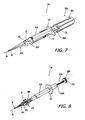
- lens insertion apparatus in accordance with at least some of the present inventions is generally represented by reference numeral 1A in FIG. 1 .
- the exemplary lens insertion apparatus 1A may be used to insert a lens 2 (e.g., an IOL) into the eye and includes a lens placement portion 3A, a tapered insertion portion 4A, a main body 5A and a plunger 6A.
- the lens 2 is loaded into the lens placement portion 3A.
- the exemplary plunger 6A includes a rod 7A that engages the lens 2 and an operational portion 8A.
- the exemplary plunger 6A is also structured such that the rod 7A may be moved in the distal direction (identified by arrow X) and the proximal direction, along axis A, through manual operation of the operational portion 8A.
- the tapered insertion portion 4A includes a nozzle 9 at the distal end and a through-hole 10 in communication with the lens placement portion 3A. During the insertion procedure, the lens 2 is pushed through the lens placement portion 3A, folded or otherwise compressed into a compact state in the tapered insertion portion 4A, and then released into the eye by way of the distal end of the nozzle 9.
- the lens 2 may be pushed by the plunger 6A, depending on the specifics of the actual implementation, through the insertion portion 4A and nozzle 9 and into the eye or, in other implementations, may be pushed over the entire range of movement from the lens placement portion 3A to the eye.
- the exemplary lens insertion apparatus 1A is a preloaded injector.
- the injector 1A is shipped with the lens 2 within the lens placement portion 3A.
- the lens placement portion 3A in the exemplary embodiment is located at the leading end of the main body 5A. More specifically, the main body 5A is formed from a cylindrical member, and the tapered insertion portion 4A is connected to the distal end of .the main body by way of the lens placement portion 3A.
- the exemplary insertion apparatus 1A also includes a longitudinally movable slider 11 with a lens control mechanism and a lock mechanism.
- the lens control mechanism (not shown) moves and deforms the lens 2 during the first stage of the insertion procedure, while the lock mechanism (not shown) prevents the plunger 6A from being moved distally until the slider 11 has been moved distally. Additional details concerning preloaded injectors that include a slider with lens control and lock mechanisms may be found in, for example, U.S. Patent Pub. No. 2010/0217273 .
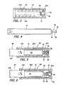
- One or more protrusions 12A may be located near the proximal end of the exemplary main body 5A. In the embodiment illustrated in FIGS. 1-7 , there are two protrusions 12A (only one is visible). Referring to FIGS. 5 and 6 , a first protrusion is located on one side wall 14A of the main body 5A, and oriented at an angle to axis A, and a second protrusion 12A is located on the opposite side wall 14A.
- the protrusions 12A define a discontinuous male screw thread (or partial screw threads) and the surfaces of the associated main body side walls 14A define the root of the screw thread(s).
- the protrusions 12A which cooperate with the helical slot 25A on operational portion 8A in the manner described below, are axially offset from one another by a distance equal to one-half of the pitch of the helical slot 25A.
- the exemplary insertion apparatus 1A illustrated in FIG. 1-7 also includes a hook (of "flange") portion 13 ( FIG. 1 ) projecting outwardly from the external surface of the main body 5A.
- the hook portion 13, which is located in the proximal half of the main body 5A, may be used to engage fingers during push-type operation of the insertion apparatus 1A.
- the insertion apparatus 1A illustrated in FIGS. 1-7 may also be provided with indicia that indicates when the relative orientation of the main body 5A and the plunger operational portion 8A is such that the operator can switch from push-type operation to screw-type operation, or from the screw-type operation to push-type operation, in the manner described below.
- the indicia consists of a first indicia portion 15 on the operational portion 8A and a second indicia portion 16A on the main body 5A.
- the first indicia portion 15 is located on the external, distal end surface of the operational portion 8A.
- the second indicia portion 16A is provided on the external surface of the main body 5A near the proximal end.
- first indicia portion 15 is in the form of a triangle and the second indicia portion 16A is in the form of a longitudinally extending linear mark.
- first and second indicia portions 15 and 16A are discussed below.
- another set of first and second indicia portions 15 and 16A may be located on the opposite sides (i.e., a location offset by 180 degrees about axis A) of the main body 5A and operational portion 8A.
- the exemplary plunger 6A is configured such that force applied to the operational portion 8A is transmitted to the rod 7A to push the lens 2 in the distal direction.
- the rod 7A includes a distal rod portion 20 and a proximal rod portion 21.
- the distal rod portion 20 has an abutting surface 19 on its distal end that engages the outer edge of the lens 2 during the insertion procedure.
- the distal rod portion 20 and the proximal rod portion 21 may be integrally formed (as shown) or separate structures that are secured to one another during assembly.
- the operational portion 8A is axially supported on the proximal rod portion 21 of the rod 7A in such a manner that the operational portion may move axially and rotationally relative to the rod, as is described in greater detail below.
- the respective configurations of the exemplary main body 5A and operational portion 8A, as well as the relationship between the two, are such that rotational movement of the operational portion results in an axial (or "longitudinal") driving force that moves the rod 7A proximally or distally depending on the direction of rotation and, in the predefined instances discussed below, force applied to the operational portion in the axial (or “longitudinal”) direction drives the rod proximally or distally depending on the direction of the force.
- the operational portion 8A of the exemplary insertion apparatus 1A includes an operational body 24, a helical slot 25A on the inner surface of the operational body, one or more clearance grooves 26A and a bearing portion 27A.
- the exemplary operational body 24 has generally cylindrical shape.
- the distal end operational body 24 is open and the bearing portion 27A is located at the proximal end.
- the helical slot 25A defines a female screw thread.
- the respective sizes, shapes and orientations of the main body protrusions 12A and the operational body helical slot 25A are such that the helical slot may be screwed into engagement with the protrusions and, once engaged, rotation of the operational portion 8A will result in axial movement of the operational portion.
- the one or more clearance grooves 26A are parallel to the lens advancing axis A and, in the illustrated embodiment, extend longitudinally over at least the entire length (measured in the axial direction) of the helical slot 25A.
- the number of clearance grooves 26A may correspond to the number of main body protrusions 12A and, accordingly, there are two clearance grooves 26A on the internal surface of the operational body 24.
- the two clearance grooves 26A are identical and located on opposite sides of the operational body 24, i.e., are offset from one another by 180 degrees about the axis A, in the illustrated embodiment.
- the clearance grooves 26A also pass through, i.e., repeatedly intersect, the helical slot 25A.
- the respective sizes, shapes and orientations of the main body protrusions 12A and the operational body clearance grooves 26A are such that, when the clearance grooves and protrusions are aligned with one another, the operational portion 8A may be moved longitudinally without rotation thereof.
- the bearing portion 27A is configured to connect to an axial support portion 36 (discussed below) located on the proximal rod portion 21.
- the exemplary bearing portion 27A includes an insertion hole 30, an inwardly protruding latching portion 31, and a cylindrical lumen 32.
- the inwardly protruding latching portion 31 is located between the insertion hole 30 and the cylindrical lumen 32.
- the end of the cylindrical lumen 32 is generally closed but for an opening 33 that is smaller in diameter than the cylindrical lumen.
- the axial support portion 36 is located on a proximal end surface 37 of the proximal rod portion 21 of the rod 7A.
- the axial support portion 36 includes an axis portion 38 and an engaging portion 39 that extends outwardly from the proximal end of the axis portion (note FIG. 4 ).
- the length of the axis portion 38 i.e., the distance from the proximal end surface 37 to the engaging portion 39, generally defines the axial distance over which the latching portion 31 and, therefore, the operational body 24 may move relative to the proximal rod portion 21 when the main body protrusions 12A are located within the clearance grooves 26A (note FIGS. 5 and 6 ).
- the operational portion 8A may be mounted on the rod 7A by inserting the axial support portion 36 into the bearing portion 27A by way of the insertion hole 30.
- the axis portion 38 will compress as the engaging portion 39 passes the latching portion 31, and then return to its expanded state, thereby preventing removal of the axial support portion 36 from the bearing portion 27A.
- the operational portion 8A is axially movable along the axis portion 38 in the proximal-distal direction over a range defined by the proximal end surface 37 and the engaging portion 39, and is also rotatable relative to the rod.
- the cylindrical body 32 of the operational body 24 is sized to accommodate such movement of the operational portion 8A. Additionally, as the diameter of the opening 33 is smaller than that of the cylindrical body 32 and engaging portion 39, the axial support portion 36 will not protrude through the end of the operational body 24.
- the respective configurations of the bearing portion 27A and the axial support portion 36 are such that the operational portion 8A can be both rotated relative to the rod 7A and moved a predetermined distance axially relative to the rod.
- the predetermined distance may be, at a minimum, the maximum distance that the operational portion 8A must travel proximally (i.e., rearward) in the axial direction as the protrusions 12A move from the helical slot 25A to the clearance grooves 26A due to rotation of the operational portion.
- the distance will be a function of the pitch of the helical slot 25A as well as the numbers of protrusions 12A and clearance grooves 26A.
- the protrusions 12A are located on opposite sides of the exemplary main body 5A, i.e., are offset from one another by 180 degrees about the axis A, and the clearance grooves 26A are located on opposite sides of the exemplary operational body 24, i.e., are offset from one another by 180 degrees about the axis A.
- one half-turn or less of the operational portion 8A is required to move the clearance grooves 26A to into alignment with the protrusions 12A. Therefore, the above-mentioned predetermined distance requires at least half of the length aspect of the pitch of the screw portion 25A.
- the exemplary lens insertion apparatus 1A may be operated as follows. First, viscoelastic material is supplied to the lens placement portion 3A, which is preloaded with a lens 2 that may be stored in a generally flat, unstressed state. The slider 11 is then moved forward, which causes the lens 2 to be pushed distally out of the lens placement portion 3A and deformed into a predetermined shape. After that, the rod 7A may be moved distally through operation of the operational portion 8A. Such operation may be rotation of the operational portion 8A while the protrusions 12A are located within the helical slot 25 (i.e., screw-type), or may be pushing the operational portion distally when the protrusions are located within the clearance grooves 26A (i.e., push-type).
- the operational portion 8A With respect to screw-type operation of the operational portion 8A, the operational portion is moved distally until the proximal end of the helical slot 25 abuts the protrusions 12A. At this point, the abutting surface 19 of rod 7A does not abut the outer edge of the lens 2. The operational portion 8A may then be rotated clockwise to engage the protrusions 12A with the helical slot 25, and subsequent rotation will be translated into axial movement of the operational portion and rod 7A. The distance that the operational portion 8A and rod 7A will move axially is a function of the pitch of the helical slot 25A and the amount of rotation.
- the rod 7A will then engage the lens 2 and drive the lens through the inside of the tapered insertion portion 4A, thereby further compressing the lens, as rotation of the operational portion 8A continues. Screw-type operation may continue, if push-type operation is not desired, until the rod 7A pushes the lens 2 through the nozzle and into the eye.
- push-type operation may proceed when the protrusions 12A are located within the clearance grooves 26A.
- the user may align the clearance grooves 26A with the protrusions 12A, and proceed with push-type operation, immediately after the slider 11 has been moved forward or after some degree of screw-type operation has taken place.
- the orientation of the operational portion 8A relative to the main body 5A must be such that the clearance grooves 26A are aligned with the protrusions 12A.
- the operational portion 8A may be advanced distally without rotation of the operational portion by simply applying a pushing force to the operational portion.
- the operation portion 8A will not rotate on its own. Also, the user will not be able to rotate the operation portion 8A when the protrusions 12A are between slot-clearance groove intersections.
- the pushing force may be applied, and the rod 7A moved forwardly, until the lens 2 enters the eye through the distal end of the nozzle 9, or until the user desires to switch to screw-type operation.
- the clearance grooves 26A also prevent rotation of the operational portion 8A unless and until the protrusions 12A are aligned with a portion of the helical slot 25A and the operator demonstrates the intent to switch to screw-type operation, precisely when there is such alignment, by applying rotational force to the operational portion. Absent the application of rotational force to the operational portion 8A when the protrusions 12A are aligned with a portion of the helical slot 25A, the clearance grooves 26A will guide the protrusions 12A (and operational portion 8A) in the axial direction and the operational portion will not rotate.
- the respective configurations of the bearing portion 27A and the axial support portion 36 are such that the operational portion 8A may be moved a predetermined distance in the proximal direction without moving the rod 7A.
- the predetermined distance is sufficient to accommodate the amount of rotation necessary to align the clearance grooves 26A with the protrusions 12A (i.e., one-half rotation or less in the embodiment illustrated in FIGS. 1-7 ). As such, contact between the rod 7A and the lens 2 may be maintained while the user switches from screw-type operation to push-type operation.
- exemplary clearance grooves 26A are formed parallel to the lens advancing axis A over the entire length of the helical slot 25A, it is possible to switch from screw-type operation to push-type operation, or from push-type operation to screw-type operation, whenever the operator desires.
- the first and second indicia portions 15 and 16A indicate, when aligned with one another, that the exemplary lens insertion apparatus 1A is susceptible to push-type operation.
- the first and second indicia portions 15 and 16A are located on the main body 5A and the operational portion 8A such that the clearance grooves 26A are aligned with the protrusions 12A when the first and second indicia portions are aligned with one another.
- the user need only rotate the operational portion 8A (if necessary) until first and second indicia portions 15 and 16A are aligned.
- the length and location of the exemplary second indicia portion 16A insures that it will be visible regardless of the position of the operational portion 8A.
- Insertion apparatus 1B is similar to insertion apparatus 1A in many respects and similar elements are represented by similar reference numerals.
- the insertion apparatus 1 B includes a main body 5B with a hook portion 51, and a plunger 6B ( FIG. 10 ) with a rod 7B and an operational portion 8B.
- the insertion apparatus 1B is a cartridge-based insertion apparatus instead of a preloaded insertion apparatus.
- an exemplary cartridge 40 includes a lens placement portion 3B, a tapered insertion portion 4B and a nozzle 9.
- a lens 2 (e.g., an IOL) may be folded and loaded into the cartridge 40, and the cartridge then secured to an attachment portion 50 located near the distal end of the main body 5B, at the time of the insertion procedure.
- the plunger 6B pushes the lens 2 from the lens placement portion, through the tapered insertion portion where it is further compressed, and then into the eye by way of the nozzle 9.
- the cartridge 40 may be removed from the attachment portion 50 after the procedure.
- the inner surface of the exemplary main body includes one or more protrusions 12B and one or more ribs 52.
- the protrusions 12B are two protrusions 12B, located 180 degrees apart, on the inner surfaces of the main body side walls 14B in the illustrated implementation.
- the protrusions 12B define a partial female screw thread and the surfaces of the associated main body side walls 14B define the root of the screw thread.
- the protrusions 12B cooperate with the operational portion 8B in the same manner as the protrusions and operational portion described above.
- the longitudinal orientation of the ribs 52 in the illustrated embodiment is parallel to the lens advancing axis A.
- the ribs 52 prevent rotation of the rod 7B, as discussed below, while allowing the rod to move parallel to the lens advancing axis A.
- the exemplary plunger rod 7B includes a distal rod portion 20 and a proximal rod portion 53.
- One or more guide grooves 54 in which the one or more ribs 52 reside, are located on the exterior of the proximal rod portion 53.
- An axial support portion 36 is located on the proximal end of the proximal rod portion 53.
- the exemplary operational portion 8B includes a disk-shaped operational body 56 and a rod-shaped body 57.
- the operational body 56 and rod-shaped body 57 may be integrally formed (as shown), or may be separate structures that are secured to one another.
- the outer diameter of the rod-shaped body 57 is substantially the same as that of the proximal rod portion 53 ( FIGS. 10 and 11 ).
- a helical slot 25B and one or more clearance grooves 26B are formed in the outer surface of the rod-shaped body 57, and a bearing portion 27B is located at the distal end of the rod-shaped body.
- the helical slot 25B defines a female screw thread and the respective sizes, shapes and orientations of the protrusions 12B and the helical slot 25B are such that the helical slot may be screwed into engagement with the protrusions and, once engaged, rotation of the operational portion 8B will result in axial movement plunger 6B.
- the one or more clearance grooves 26B are parallel to the lens advancing axis A and, in the illustrated embodiment, extend longitudinally over at least the entire length (measured in the axial direction) of the helical slot 25B.
- the number of clearance grooves 26B may correspond to the number of main body protrusions 12B and, accordingly, there are two clearance grooves 26B on the external surface of the rod-shaped body 57.
- the clearance grooves 26B in the illustrated embodiment are located on opposite sides of the rod-shaped body 57, i.e., are offset from one another by 180 degrees about the axis A.
- the clearance grooves 26B also pass through, i.e., repeatedly intersect, the helical slot 25B.
- the respective sizes, shapes and orientations of the main body protrusions 12B and the operational body clearance grooves 26B are such that, when the clearance grooves and protrusions are aligned with one another, the operational portion 8B may be moved longitudinally, without rotation thereof.
- the exemplary bearing portion 27B includes the insertion hole 30, latching portion 31, and cylindrical body 32 described above.
- the bearing portion 27B ( FIG. 12 ) and axial support portion 36 ( FIG. 11 ) operate in the manner describe above with reference to FIGS. 5 and 6 to facilitate axial movement of the operational portion 8B relative to the rod 7B.
- Such axial movement facilitates switching from screw-type operation to push-type operation, or from push-type operation to screw-type operation, whenever the operator desires, as is also described above. To that end, and referring to FIG.
- the exemplary insertion apparatus 1 B is provided with first and second indicia 15 and 16B on the main body 5B and operational portion 8B that may be used to align the main body protrusions 12B and clearance grooves 26B in the manner also described above.
- Another set of first and second indicia portions 15 and 16B may be located on the opposite sides (i.e., locations offset by 180 degrees about axis A) of the main body 5B and operational portion 8B in some implementations.
- the first display portion may be omitted.
- a lens insertion apparatus that, for example, is otherwise identical to the lens insertion apparatus 1A illustrated in FIGS. 1-7 in form and operation may be configured such that the locations of the one or more protrusions, the one or more clearance grooves, and the helical slot are reversed.
- the exemplary lens insertion apparatus 1C illustrated in FIG. 13-15 includes, for example, a main body 5C and a plunger 6C.
- the plunger 6C includes a rod 7C and an operational portion 8C.
- the rod 7C includes a distal rod portion (not shown), a proximal rod portion 21 and an axial support portion 36.
- the operational portion 8C includes an operational body 24 and a bearing portion 27C.
- the insertion apparatus 1C also includes a lens placement portion, tapered insertion portion, and nozzle, which are not shown.
- the operational portion 8C includes one or more protrusions 12C.
- the protrusions 12C define a partial male screw thread and the inner surface of the operational body 24 defines the root of the screw thread.
- a helical slot 25C and one or more clearance grooves 26C are formed on the outer surface of the main body 5C.
- the helical slot 25C defines a female screw thread and the respective sizes, shapes and orientations of the protrusions 12C and the helical slot are such that the protrusions may be screwed into engagement with the helical slot and, once engaged, rotation of the operational portion 8C will result in axial movement plunger 6C.
- the one or more clearance grooves 26C are parallel to the lens advancing axis A and, in the illustrated embodiment, extend longitudinally over at least the entire length (measured in the axial direction) of the helical slot 25C.
- the number of clearance grooves 26C may correspond to the number of main body protrusions 12C and, accordingly, there are two clearance grooves 26C on the external surface of the main body 5C.
- the clearance grooves 26C in the illustrated embodiment are located on opposite sides of the main body 5C, i.e., are offset from one another by 180 degrees about the axis A.
- the clearance grooves 26C also pass through, i.e., repeatedly intersect, the helical slot 25C.
- the respective sizes, shapes and orientations of the operational portion protrusions 12C and the main body clearance grooves 26C are such that, when the clearance grooves and protrusions are aligned with one another, the operational portion 8C may be moved longitudinally without rotation thereof.
- Lens insertion apparatus 1D is substantially similar in form and operation to the lens insertion apparatus 1B illustrated in FIGS. 8-12 and similar elements are represented by similar reference numerals.
- the insertion apparatus 1 D is cartridge-based and includes a main body 5D with a hook portion 51, and a plunger 6D with a rod 7D and an operational portion 8D.
- the inner surface of the exemplary main body 5D includes a helical slot 25D, one or more clearance grooves 26D, and one or more guide grooves 54D.
- the clearance and guide grooves 26D and 54D may be combined into single grooves (as shown) or may be separate grooves.
- the rod 7D includes a distal rod portion 20 and a proximal rod portion 53 with one or more ribs 52D that reside in the guide groves 54D.
- the operational portion 8D has a disk-shaped operational body 56 and a rod-shaped body 57 that may be connected to one another in the manner described above (i.e., with a bearing portion and axial support portion).
- One or more protrusions 12D are carried on the outer surface of the rod-shaped body.
- the operational body 56 and rod-shaped body 57 may be integrally formed (as shown), or may be separate structures that are secured to one another.
- ribs or “rails” or “mechanical keys” 52D, located 180 degrees apart, and there are two guide grooves 54D, also located 180 degrees apart, that together prevent rotation of the rod 7D while allowing the rod to move parallel to the lens advancing axis A.
- protrusions 12D located 180 degrees apart.
- the protrusions 12D define a partial male screw thread and the surface of the rod-shaped body 57 defines the root of the screw thread.
- the helical slot 25D defines a female screw thread and the respective sizes, shapes and orientations of the protrusions 12D and the helical slot 25D are such that the protrusions may be screwed into engagement with the helical slot and, once engaged, rotation of the operational portion 8D will result in axial movement plunger 6D.
- the one or more clearance grooves 26D are parallel to the lens advancing axis A and, in the illustrated embodiment, extend longitudinally over at least the entire length (measured in the axial direction) of the helical slot 25D. There are two clearance grooves 26D, offset from one another by 180 degrees, in the illustrated embodiment. The clearance grooves 26D also pass through, i.e., repeatedly intersect, the helical slot 25D.
- the respective sizes, shapes and orientations of the main body protrusions 12D and the clearance grooves 26D are such that, when the clearance grooves and protrusions are aligned with one another, the operational portion 8D may be moved longitudinally without rotation thereof.
- FIGS. 1-16 each include two protrusions that are 180 degrees apart and two clearance grooves that are 180 degrees apart.
- the present inventions are not, however, so limited. For example, there may be one, three, four or more of each. For example, there may be four spaced protrusions, offset by 90 degrees, which follow the pitch of the associated helical slot.
- the exemplary lens insertion apparatus 1 E illustrated therein is substantially similar to the insertion apparatus 1A described above with reference to FIGS. 1-7 in form and operation.
- the insertion apparatus 1E includes, among other things, a main body 5E and a plunger 6E with a rod 7E and an operational portion 8E.
- the main body 5E has a hook portion 13E, an annular wall 14E and a plurality of protrusions 12E.
- the rod 7E has a distal rod portion (not shown) and a proximal rod portion 21.
- the operational portion 8E has an operational body 24E, a helical slot 25E, clearance grooves 26E and a bearing portion 27E that is connected to an axial support portion as is described above.
- lens insertion apparatus 1E has a plurality of protrusions 12E that are spaced circumferentially and axially on the main body 5E.
- the protrusions define a male screw thread.
- the protrusions 12E are aligned in four linear rows in the axially direction, which are parallel to axis A, and adjacent rows are circumferentially offset by 90 degrees.
- the inner surface of the operational portion 8E has four clearance grooves 26E that are separated by axially extending protrusions 28E.
- the operational portion 8E During screw-type operation of the lens operational portion 8E, rotation of the operational portion while the protrusions 12E are in the helical slot 25E is translated into axial movement of the operational portion and rod 7E.
- the user may switch to push-type operation by aligning the clearance grooves 26E with the rows of protrusions 12E.
- the operational portion 8E also has a window 29E, which is aligned with one of the protrusions 28E, that allows the user to determine whether the clearance grooves 26E and the rows of protrusions 12E are aligned. In the orientation illustrated in the FIG.
- the main body protrusions 12E are aligned with the operational portion protrusions 28E, thereby limiting operation to screw-type operation, and some of the main body protrusions are visible the window 29E.
- the window 29E makes it easier to grip the operational portion 8E during screw-type operation.
- the orientation illustrated in FIG. 20 is 90 degrees offset from the orientation illustrated in FIG. 19 .
- the four clearance grooves 26E are aligned with the four rows of protrusions 12E, thereby enabling push-type operation, and no protrusions 12E are visible through the window 29E.
- Insertion apparatus 1A-1 is essentially identical to the insertion apparatus 1A described above with reference to FIGS. 1-7 .
- One advantage of the use of rows of multiple axially spaced protrusions 12A, both here and the apparatus illustrated in FIGS. 17-20 is that it increases the stability of the movement of the operational portions during screw-type and push-type operation.
- the exemplary protrusions discussed above have shapes corresponding to a portion of a screw thread.
- the protrusions may be other shapes such as, for example, semispherical, elliptical or other curved shapes.
- the exemplar operational portion 8C-1 illustrated in FIG. 22 includes one or more hemispherical projections 12C-1 and the exemplary main body 5A-1 illustrated in FIG. 23 includes one or more semi-ellipsoidal projections 12A-1.
- Such curved shapes make the transition from one type of operation (e.g., screw-type) to the other (e.g., push-type) easier and less abrupt.
- intersections between the helical slot and the one or more clearance grooves may include curved corners in embodiments that may be otherwise identical to any of the embodiments described above.
- operational portion 8A-2 includes curved corners 41 at the intersections of the helical slot 25A and the one or more clearances grooves 26A.
- the curved shape makes the transition from one type of operation to the other easier and less abrupt.
- the present inventions are not limited to the exemplary embodiments described above.
- the number of protrusions may or may not be equal to the number of the clearance grooves.
- the number of clearance grooves may be greater than the number of protrusions in those instances where the numbers are not equal.
- the pitches of the helical slots are constant in the embodiments described above, the pitches may vary along the axial length of the slots.
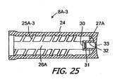
- the pitch of the slot may be smaller near the proximal end of the operational portion, for example, so that operational portion controls the travel distance of the lens more accurately as the lens is passing through the distal end of the insertion portions.
- the operational portion 8A-3 in FIG. 25 includes a helical slot 25A-3 with a pitch that is smaller near the proximal end of the operational portion.
- the orientation of the helical slots may also be reversed so that counterclockwise rotation of the results in distal movement of the operational portion.
Landscapes
- Health & Medical Sciences (AREA)
- Ophthalmology & Optometry (AREA)
- Cardiology (AREA)
- Oral & Maxillofacial Surgery (AREA)
- Transplantation (AREA)
- Engineering & Computer Science (AREA)
- Biomedical Technology (AREA)
- Heart & Thoracic Surgery (AREA)
- Vascular Medicine (AREA)
- Life Sciences & Earth Sciences (AREA)
- Animal Behavior & Ethology (AREA)
- General Health & Medical Sciences (AREA)
- Public Health (AREA)
- Veterinary Medicine (AREA)
- Prostheses (AREA)
Claims (20)
- Appareil d'insertion pour un implant oculaire, comprenant :un corps principal (5A, 5A-1, 5B, 5C, 5D, 5E) définissant un axe longitudinal ;un plongeur (6A, 6B, 6C, 6D, 6E), déplaçable par rapport au corps principal, incluant une portion en tige (7A, 7B, 7C, 7D, 7E) et une portion fonctionnelle (8A, 8A-2, 8A-3, 8B, 8C, 8C-1, 8D, 8E) montée rotative sur la portion en tige ;caractérisé en ce queun des éléments parmi le corps principal et la portion fonctionnelle inclut une fente hélicoïdale (25A, 25A-3, 25B, 25C, 25D, 25E) et au moins une gorge de dégagement (26A, 26B, 26C, 26D, 26E) s'étendant longitudinalement, qui recoupe la fente hélicoïdale ; etl'autre élément parmi le corps principal et la portion fonctionnelle inclut au moins une projection (12A, 12A-1, 12B, 12C, 12C-1, 12D, 12E), qui présente une taille et une forme propres à se loger dans la fente hélicoïdale et dans ladite au moins une gorge de dégagement s'étendant longitudinalement.
- Appareil d'insertion pour un implant oculaire selon la revendication 1, comprenant en outre :une portion de mise en place d'implant (3A, 3B) associée au corps principal et configurée pour tenir un implant oculaire (2).
- Appareil d'insertion pour implant oculaire selon la revendication 2, dans lequel la portion de mise en place d'implant (3A) est fixée de manière permanente au corps principal (5A, 5A-1, 5C, 5E).
- Appareil d'insertion pour implant oculaire selon la revendication 2, dans lequel la portion de mise en place d'implant (3B) comprend une cartouche.
- Appareil d'insertion pour implant oculaire selon les revendications 1 à 4, dans lequel la portion fonctionnelle (8A, 8A-2, 8A-3, 8B, 8C, 8C-1, 8D, 8E) est montée sur la portion en tige (7A, 7B, 7C, 7D, 7E) de telle façon que la portion fonctionnelle est mobile longitudinalement sur une distance prédéterminée par rapport à la portion en tige.
- Appareil d'insertion pour implant oculaire selon la revendication 5, dans lequel la distance prédéterminée est égale à un pas de la fente hélicoïdale (25A, 25A-3 ,25B, 25C, 25D, 25E).
- Appareil d'insertion pour implant oculaire selon les revendications 1 à 6, dans lequel ladite au moins une gorge de dégagement s'étendant longitudinalement (26A, 26B, 26C, 26D, 26E) comprend une première et une seconde gorge de dégagement ; et
ladite au moins une projection (12A, 12A-1, 12B, 12C, 12C-1, 12D, 12E) comprend une première et une seconde projection. - Appareil d'insertion pour implant oculaire selon les revendications 1 à 6, dans lequel ladite au moins une rainure de dégagement s'étendant longitudinalement (26A, 26E) comprend une première et une seconde gorge de dégagement ; et
ladite au moins une projection (12A, 12E) comprend une première et une seconde rangée, s'étendant axialement, de projections. - Appareil d'insertion pour implant oculaire selon les revendications 1 à 8, comprenant en outre :des premiers indices (15) sur la portion fonctionnelle et des seconds indices (16A, 16B) sur le corps principal, positionnés de telle façon que ladite au moins une gorge de dégagement et au moins une projection soient alignées quand les premiers et les seconds indices sont alignés.
- Appareil d'insertion pour implant oculaire selon les revendications 1 à 8, comprenant en outre :une fenêtre (29E) s'étendant à travers la portion fonctionnelle (8E) et positionnée de telle façon que ladite au moins une gorge de dégagement (26E) et au moins une projection (12E) soient alignées quand la fenêtre est alignée avec ladite au moins une gorge de dégagement.
- Appareil d'insertion pour implant oculaire selon les revendications 1 à 10, dans lequel la fente hélicoïdale (25A, 25B, 25C, 25D, 25E) définit une longueur axiale et un pas, et le pas est sensiblement constant sur la longueur axiale.
- Appareil d'insertion pour implant oculaire selon les revendications 1 à 10, dans lequel la fente hélicoïdale (25A-3) définit une longueur axiale et un pas, et le pas n'est pas sensiblement constant sur la longueur axiale.
- Appareil d'insertion pour implant oculaire selon les revendications 1 à 12, dans lequel ladite au moins une projection (12A, 12B, 12C, 12D, 12E) définit une forme correspondant à un pas de vis partiel.
- Appareil d'insertion pour implant oculaire selon les revendications 1 à 12, dans lequel ladite au moins une projection (12A-1, 12C-1) définit une forme incurvée.
- Appareil d'insertion pour implant oculaire selon les revendications 1 à 14, dans lequel la fente hélicoïdale (25A) et ladite au moins une gorge de dégagement s'étendant longitudinalement (26A) définissent une pluralité de coins incurvés (41) à leurs intersections.
- Appareil d'insertion pour implant oculaire selon les revendications 1 à 15, dans lequel la portion fonctionnelle va se déplacer axialement en réponse à l'application d'une force axiale à celle-ci quand ladite au moins une projection (12A, 12A-1, 12B, 12C, 12C-1, 12D, 12E) se trouvent dans ladite au moins une gorge de dégagement (26A, 26B, 26C, 26D, 26E),
- Appareil d'insertion pour implant oculaire selon les revendications 1 à 16, dans lequel la portion fonctionnelle () va se déplacer en rotation et axialement en réponse à l'application d'une force de rotation à celle-ci quand ladite au moins une projection (12A, 12A-1, 12B, 12C, 12C-1, 12D, 12E) se trouve dans la fente hélicoïdale (25A, 25A-3, 25B, 25C, 25D, 25E).
- Appareil d'insertion pour implant oculaire selon les revendications 1 à 17, dans lequel la portion fonctionnelle (8A, 8A-2, 8A-3, 8B, 8C, 8C-1, 8D, 8E) ne va pas se déplacer en rotation en réponse à l'application d'une force de rotation à celle-ci quand ladite au moins une projection (12A, 12A-1, 12B, 12C, 12C-1, 12D, 12E) se trouve dans la gorge de dégagement (26A, 26B, 26C, 26D, 26E) entre des portions de la fente hélicoïdale (25A, 25A-3, 25B, 25C, 25D, 25E).
- Système comprenant un appareil d'insertion pour implant oculaire selon les revendications 1 à 18, et dans lequel l'implant oculaire (2) comprend une lentille.
- Système comprenant un appareil d'insertion pour implant oculaire selon la revendication 19, et dans lequel la lentille comprend une lentille intraoculaire.
Applications Claiming Priority (2)
| Application Number | Priority Date | Filing Date | Title |
|---|---|---|---|
| JP2010089186 | 2010-04-08 | ||
| PCT/JP2011/059131 WO2011126144A1 (fr) | 2010-04-08 | 2011-04-06 | Appareil d'insertion d'implants oculaires et méthodes associées |
Publications (3)
| Publication Number | Publication Date |
|---|---|
| EP2555708A1 EP2555708A1 (fr) | 2013-02-13 |
| EP2555708A4 EP2555708A4 (fr) | 2013-12-04 |
| EP2555708B1 true EP2555708B1 (fr) | 2015-03-18 |
Family
ID=44763076
Family Applications (1)
| Application Number | Title | Priority Date | Filing Date |
|---|---|---|---|
| EP11766042.3A Active EP2555708B1 (fr) | 2010-04-08 | 2011-04-06 | Appareil d'insertion d'implants oculaires |
Country Status (5)
| Country | Link |
|---|---|
| US (1) | US9326847B2 (fr) |
| EP (1) | EP2555708B1 (fr) |
| JP (1) | JP5735531B2 (fr) |
| SG (1) | SG184032A1 (fr) |
| WO (1) | WO2011126144A1 (fr) |
Families Citing this family (36)
| Publication number | Priority date | Publication date | Assignee | Title |
|---|---|---|---|---|
| EP1832247B1 (fr) | 2004-12-27 | 2015-06-24 | Hoya Corporation | Dispositif d'implantation de lentille intraoculaire |
| US8545512B2 (en) | 2005-01-26 | 2013-10-01 | Hoya Corporation | Intraocular lens insertion device |
| JP4836046B2 (ja) | 2005-02-24 | 2011-12-14 | Hoya株式会社 | 眼内レンズ挿入器具 |
| WO2007037223A1 (fr) | 2005-09-28 | 2007-04-05 | Hoya Corporation | Instrument pour insérer un cristallin artificiel |
| JP4877643B2 (ja) | 2005-12-08 | 2012-02-15 | Hoya株式会社 | 眼内レンズ挿入用器具 |
| JP5236637B2 (ja) * | 2007-05-30 | 2013-07-17 | Hoya株式会社 | 眼内レンズ挿入器具及び眼内レンズ挿入装置 |
| WO2008149795A1 (fr) | 2007-05-30 | 2008-12-11 | Hoya Corporation | Outil utilisé pour l'insertion d'une lentille intraoculaire |
| JP5086713B2 (ja) | 2007-07-11 | 2012-11-28 | Hoya株式会社 | 眼内レンズ挿入器具 |
| JP5254669B2 (ja) | 2008-06-05 | 2013-08-07 | Hoya株式会社 | 眼内レンズ挿入器具及びカートリッジ |
| JP5470753B2 (ja) | 2008-06-17 | 2014-04-16 | Hoya株式会社 | 眼内レンズ挿入器具 |
| JP5323420B2 (ja) | 2008-08-21 | 2013-10-23 | Hoya株式会社 | 眼内レンズ挿入器具 |
| JP5416379B2 (ja) | 2008-09-04 | 2014-02-12 | Hoya株式会社 | 眼内レンズ挿入器具 |
| CN102307543B (zh) | 2009-01-07 | 2015-10-21 | Hoya株式会社 | 眼内透镜插入器具 |
| JP5511530B2 (ja) | 2010-06-10 | 2014-06-04 | Hoya株式会社 | 眼内レンズ挿入装置 |
| GB2501109B (en) | 2012-04-12 | 2014-04-23 | Duckworth & Kent Ltd | Actuator for device for delivery of ophthalmic lenses |
| JP6071349B2 (ja) * | 2012-09-05 | 2017-02-01 | 興和株式会社 | 眼内レンズの挿入器具及び、挿入器具の補助装置 |
| GB2517921B (en) * | 2013-09-04 | 2015-12-16 | Duckworth & Kent Ltd | Device for use in a delivery of ophthalmic lenses |
| JP6276619B2 (ja) * | 2014-03-19 | 2018-02-07 | Hoya株式会社 | 眼内レンズ挿入器および眼内レンズ挿入装置 |
| US9838576B2 (en) | 2015-08-31 | 2017-12-05 | Panasonic Corporation | Endoscope |
| AU2016324545A1 (en) | 2015-09-16 | 2018-04-12 | Hoya Corporation | Intraocular lens insertion tool |
| JP6646987B2 (ja) | 2015-09-16 | 2020-02-14 | Hoya株式会社 | 眼内レンズ挿入器具 |
| TWI674684B (zh) * | 2015-12-30 | 2019-10-11 | 晶元光電股份有限公司 | 發光裝置以及其製造方法 |
| US11033382B2 (en) | 2016-06-28 | 2021-06-15 | Hoya Corporation | Intraocular lens injector |
| WO2018003853A1 (fr) | 2016-06-28 | 2018-01-04 | Hoya株式会社 | Instrument d'insertion de lentille intraoculaire |
| US10426602B2 (en) * | 2017-10-05 | 2019-10-01 | Ast Products, Inc. | Intraocular lens (IOL) injector and method of use thereof |
| CH714883B1 (de) * | 2018-04-12 | 2025-11-14 | Medicel Ag | Injektor mit Anschlagelement |
| JP7162443B2 (ja) | 2018-05-16 | 2022-10-28 | Hoya株式会社 | 容器付き眼内リング挿入器 |
| JP7162445B2 (ja) | 2018-05-25 | 2022-10-28 | Hoya株式会社 | 眼内レンズ挿入器 |
| TW202005618A (zh) * | 2018-07-10 | 2020-02-01 | 瑞士商愛爾康股份有限公司 | 人工晶狀體注入器 |
| US11116626B2 (en) * | 2018-12-19 | 2021-09-14 | Alcon Inc. | IOL injector having a lever-driven plunger mechanism |
| US11324590B2 (en) * | 2018-12-19 | 2022-05-10 | Alcon Inc. | Collapsing push injector with hydraulic damping |
| US11439500B2 (en) * | 2018-12-20 | 2022-09-13 | Alcon Inc. | IOL injector with automatic driver or assisted manual drive force |
| US11957569B2 (en) | 2019-02-28 | 2024-04-16 | Tissuecor, Llc | Graft tissue injector |
| JP7327956B2 (ja) | 2019-03-13 | 2023-08-16 | Hoya株式会社 | 眼内レンズ挿入器具 |
| DE102021112682B3 (de) * | 2021-05-17 | 2022-09-15 | Iolution Gmbh | Injektor mit Drehelement für eine Intraokularlinse |
| US12090262B2 (en) | 2021-09-01 | 2024-09-17 | Tissuecor, Llc | Device and system for injecting biological tissue |
Family Cites Families (211)
| Publication number | Priority date | Publication date | Assignee | Title |
|---|---|---|---|---|
| US2761446A (en) | 1955-03-30 | 1956-09-04 | Chemical Specialties Co Inc | Implanter and cartridge |
| US4205747A (en) | 1978-09-05 | 1980-06-03 | Cilco, Inc. | Lens storage device |
| US4269307A (en) | 1979-08-09 | 1981-05-26 | Iolab Corporation | Intraocular lens storage assembly |
| US4573998A (en) | 1982-02-05 | 1986-03-04 | Staar Surgical Co. | Methods for implantation of deformable intraocular lenses |
| US4702244A (en) | 1982-02-05 | 1987-10-27 | Staar Surgical Company | Surgical device for implantation of a deformable intraocular lens |
| US4423809A (en) | 1982-02-05 | 1984-01-03 | Staar Surgical Company, Inc. | Packaging system for intraocular lens structures |
| US4608049A (en) | 1982-06-28 | 1986-08-26 | Kelman Charles D | Intraocular lens and method of inserting an intraocular lens into an eye |
| US4634423A (en) | 1984-04-30 | 1987-01-06 | Bailey Jr Paul F | Ophthalmological method and instrument for implantation of posterior chamber intraocular lens |
| US4787904A (en) | 1984-07-06 | 1988-11-29 | Severin Sanford L | Hydrophillic intraocular lens |
| US4699140A (en) | 1985-07-10 | 1987-10-13 | Iolab Corporation | Instrument for inserting an intraocular lens |
| US4681102A (en) | 1985-09-11 | 1987-07-21 | Bartell Michael T | Apparatus and method for insertion of an intra-ocular lens |
| US4715373A (en) | 1985-09-27 | 1987-12-29 | Mazzocco Thomas R | Devices for implantation of deformable intraocular lens structures |
| US4750498A (en) | 1986-02-21 | 1988-06-14 | Coopervision, Inc. | Method and tool for inserting an intraocular lens |
| DE3610925C2 (de) | 1986-03-24 | 1994-11-03 | Michael Ulrich Prof D Dardenne | Vorrichtung zum Falten einer insbesondere mit zwei seitlichen Kunststoffhaptikplatten versehenen, implantierbaren Intraokularlinse und zum Einbringen der gefalteten Intraokularlinse in das Auge |
| US4697697A (en) | 1986-08-18 | 1987-10-06 | Coopervision, Inc. | Method and apparatus for packaging an intraocular lens |
| JPS63197453A (ja) | 1986-11-07 | 1988-08-16 | ザ・クーパー・カンパニー・インク | 圧縮性眼内レンズを眼に挿入する器具および方法 |
| US4919130A (en) | 1986-11-07 | 1990-04-24 | Nestle S.A. | Tool for inserting compressible intraocular lenses into the eye and method |
| US4747404A (en) | 1986-11-10 | 1988-05-31 | Kresge Eye Institute Of Wayne State University | Foldable intraocular lens inserter |
| US4763650A (en) | 1987-01-20 | 1988-08-16 | Hauser Stephen G | Instrument for inserting a deformable lens into the eye |
| US4810249A (en) * | 1987-03-12 | 1989-03-07 | Habley Medical Technology Corp. | Linear and Vernier-type syringe |
| US4994028A (en) | 1987-03-18 | 1991-02-19 | Endocon, Inc. | Injector for inplanting multiple pellet medicaments |
| US4988352A (en) | 1987-03-26 | 1991-01-29 | Poley Brooks J | Method and apparatus for folding, freezing and implanting intraocular lens |
| US5176686A (en) | 1987-03-26 | 1993-01-05 | Poley Brooks J | Apparatus for packaging, folding, rigidifying and inserting an intraocular lens |
| US4819631A (en) | 1987-03-26 | 1989-04-11 | Poley Brooks J | Folded intraocular lens, method of implanting it, retainer, and apparatus for folding lens |
| US4769034A (en) | 1987-03-26 | 1988-09-06 | Poley Brooks J | Folded intraocular lens, method of implanting folded intraocular lens |
| US4781719A (en) | 1987-07-28 | 1988-11-01 | Kelman Charles D | Method of inserting an intraocular lens into an eye |
| US4759359A (en) | 1987-08-31 | 1988-07-26 | Allergan, Inc. | Lens implantation instrument |
| US4834094A (en) | 1987-10-07 | 1989-05-30 | Patton Medical Technologies, Inc. | "Canoe" apparatus for inserting intra-ocular lens into the eye |
| US4765329A (en) | 1987-10-19 | 1988-08-23 | Cumming, Redwitz & Wilson, Inc. | Intraocular lens insertion instrument |
| US4934363A (en) | 1987-12-15 | 1990-06-19 | Iolab Corporation | Lens insertion instrument |
| US4880000A (en) | 1987-12-15 | 1989-11-14 | Iolab Corporation | Lens insertion instrument |
| US4836201A (en) | 1988-03-24 | 1989-06-06 | Patton Medical Technologies, Inc. | "Envelope" apparatus for inserting intra-ocular lens into the eye |
| US4862885A (en) | 1988-05-25 | 1989-09-05 | Cumming J Stuart | Instrument for inserting a deformable intraocular lens into the eye |
| AU623934B2 (en) | 1988-10-07 | 1992-05-28 | Ioptex Research Inc | Intraocular lens insertion instrument |
| US4976716A (en) | 1989-01-23 | 1990-12-11 | Cumming J Stuart | Intraocular lens insertion device |
| US5066297A (en) | 1989-01-23 | 1991-11-19 | Cumming J Stuart | Intraocular lens insertion device |
| US4955889A (en) | 1989-02-06 | 1990-09-11 | Allergan, Inc. | Apparatus for inserting a lens into an eye and method for using same |
| US5222972A (en) | 1989-04-12 | 1993-06-29 | Allergan, Inc. | Small incision intraocular lens insertion apparatus |
| US5098439A (en) | 1989-04-12 | 1992-03-24 | Allergan, Inc. | Small incision intraocular lens insertion apparatus |
| US5171241A (en) | 1989-06-09 | 1992-12-15 | Ioptex Research Inc. | Device for folding an intraocular lens and holding it in the folded state |
| DE4030492C1 (fr) | 1990-09-26 | 1991-09-05 | Adatomed Pharmazeutische Und Medizintechnische Gesellschaft Mbh, 8000 Muenchen, De | |
| DE4039119C1 (fr) | 1990-12-07 | 1991-09-05 | Dieter Dr.Med. 8904 Friedberg De Klaas | |
| DE4108303C2 (de) | 1991-03-14 | 1993-11-04 | Adatomed Pharma & Med | Verfahren und vorrichtung zum einbringen einer gummielastischen intraokularlinse in ein implantationswerkzeug |
| DE4110278A1 (de) | 1991-03-28 | 1992-10-01 | Geuder Hans Gmbh | Augenchirurgisches instrument zum implantieren von hinterkammer-weichlinsen |
| DE4112259A1 (de) * | 1991-04-15 | 1992-10-22 | Medico Dev Investment Co | Injektionsgeraet |
| US5123905A (en) | 1991-06-07 | 1992-06-23 | Kelman Charles D | Intraocular lens injector |
| JPH0779825B2 (ja) | 1991-06-13 | 1995-08-30 | キヤノンスター株式会社 | 眼内レンズの移植器具 |
| JPH0779826B2 (ja) | 1991-06-14 | 1995-08-30 | キヤノンスター株式会社 | 眼内レンズの移植器具 |
| US5259395A (en) * | 1992-01-15 | 1993-11-09 | Siemens Pacesetter, Inc. | Pacemaker lead with extendable retractable lockable fixing helix |
| US5190552A (en) | 1992-02-04 | 1993-03-02 | Kelman Charles D | Slotted tube injector for an intraocular lens |
| US5242450A (en) | 1992-05-18 | 1993-09-07 | Henry H. McDonald | Eye implantable lens haptics twist apparatus |
| US5395378A (en) | 1992-05-18 | 1995-03-07 | Henry H. McDonald | Eye implantable lens haptics insertion and twist apparatus |
| US5571113A (en) | 1992-05-18 | 1996-11-05 | Henry H. McDonald | Surgical probe with tips for plastic lens implantation in the eye |
| US5304182A (en) | 1992-09-23 | 1994-04-19 | Kabi Pharmacia Ophthalmics, Inc. | Apparatus and method for curling and inserting flexible intraocular lenses |
| PT723429E (pt) | 1992-09-30 | 2002-09-30 | Vladimir Feingold | Sistema de insercao de lentes intra-oculares |
| US6506195B2 (en) | 1992-09-30 | 2003-01-14 | Staar Surgical Company, Inc. | Deformable intraocular lens insertion system |
| US5928245A (en) | 1992-09-30 | 1999-07-27 | Staar Surgical Company, Inc. | Deformable intraocular lens injecting apparatus with transverse hinged lens cartridge |
| US5616148A (en) | 1992-09-30 | 1997-04-01 | Staar Surgical Company, Inc. | Transverse hinged deformable intraocular lens injecting apparatus |
| US6712848B1 (en) | 1992-09-30 | 2004-03-30 | Staar Surgical Company, Inc. | Deformable intraocular lens injecting apparatus with transverse hinged lens cartridge |
| US5772666A (en) | 1992-09-30 | 1998-06-30 | Staar Surgical Company, Inc. | Deformable intraocular lens injecting apparatus with deformable tip plunger |
| US5620450A (en) | 1992-09-30 | 1997-04-15 | Staar Surgical Company, Inc. | Transverse hinged deformable intraocular lens injecting apparatus |
| US5499987A (en) | 1992-09-30 | 1996-03-19 | Staar Surgical Company | Deformable intraocular lens cartridge |
| US5807400A (en) * | 1992-09-30 | 1998-09-15 | Staar Surgical Company, Inc. | Deformable intraocular lens insertion system |
| US5941886A (en) | 1992-09-30 | 1999-08-24 | Staar Surgical Company, Inc. | Hingeless lens cartridges for insertion of deformable intraocular lens |
| US5728102A (en) | 1992-09-30 | 1998-03-17 | Staar Surgical Company, Inc. | Disposable intraocular lens insertion system |
| US6059791A (en) | 1992-09-30 | 2000-05-09 | Staar Surgical Company, Inc. | Deformable intraocular lens injection system, and method thereof |
| US6001107A (en) | 1992-09-30 | 1999-12-14 | Staar Surgical Company, Inc. | Deformable intraocular lens injecting apparatus |
| US6406481B2 (en) | 1992-09-30 | 2002-06-18 | Starr Surgical Company, Inc. | Method preloading a deformable intraocular lens into injecting apparatus for storage and/or shipment |
| US5860984A (en) | 1992-09-30 | 1999-01-19 | Staar Surgical Company, Inc. | Spring biased deformable intraocular injecting apparatus |
| US6056757A (en) | 1992-09-30 | 2000-05-02 | Staar Surgical Company, Inc. | Implantation device with deformable nozzle tip for implanting a deformable intraocular lens |
| US6022358A (en) | 1992-09-30 | 2000-02-08 | Staar Surgical Company, Inc. | Deformable intraocular lens injecting device |
| US5876440A (en) | 1992-09-30 | 1999-03-02 | Staar Surgical Company, Inc. | Methods of implantation of deformable intraocular lens |
| US5281227A (en) | 1992-11-09 | 1994-01-25 | Allergan, Inc. | Lens case with IOL folding device |
| US5275604A (en) | 1992-12-03 | 1994-01-04 | Kabi Pharmacia Ophthalmics, Inc. | Contoured duct apparatus and method for insertion of flexible intraocular lens |
| US5653715A (en) | 1993-03-09 | 1997-08-05 | Chiron Vision Corporation | Apparatus for preparing an intraocular lens for insertion |
| US5425734A (en) | 1993-07-02 | 1995-06-20 | Iovision, Inc. | Intraocular lens injector |
| US5468246A (en) | 1993-07-02 | 1995-11-21 | Iovision, Inc. | Intraocular lens injector |
| JP3459664B2 (ja) | 1993-07-15 | 2003-10-20 | キヤノンスター株式会社 | 変形可能な眼内レンズの挿入器具 |
| SE9303568D0 (sv) * | 1993-10-29 | 1993-10-29 | Kabi Pharmacia Ab | Improvements in injection devices |
| US5584304A (en) | 1993-11-18 | 1996-12-17 | Allergan, Inc. | Method of inserting an IOL using a forceps inside a folding tube |
| WO1995013766A1 (fr) | 1993-11-18 | 1995-05-26 | Allergan, Inc. | Appareil servant a implanter dans l´×il des lentilles souples |
| US5702402A (en) | 1994-04-29 | 1997-12-30 | Allergal | Method and apparatus for folding of intraocular lens |
| US5582613A (en) | 1993-11-18 | 1996-12-10 | Allergan | Apparatus and methods for controlled insertion of intraocular lenses |
| AU1915595A (en) | 1994-02-09 | 1995-08-29 | Kabi Pharmacia Ophthalmics, Inc. | Rapid implantation of shape transformable optical lenses |
| US6174315B1 (en) | 1994-02-15 | 2001-01-16 | Staar Surgical Company, Inc. | Spring biased deformable intraocular injecting apparatus |
| US5578042A (en) | 1994-03-14 | 1996-11-26 | Cumming; J. Stuart | Ophthalmic kit and method for lens insertion |
| US5645534A (en) * | 1994-06-24 | 1997-07-08 | Becton Dickinson And Company | Time of last injection indicator for medication delivery pen |
| JP3412106B2 (ja) | 1994-07-07 | 2003-06-03 | キヤノンスター株式会社 | 変形可能な眼内レンズの挿入器具 |
| JP3412107B2 (ja) | 1994-07-18 | 2003-06-03 | キヤノンスター株式会社 | 変形可能な眼内レンズの挿入器具 |
| US5454818A (en) | 1994-07-26 | 1995-10-03 | Alcon Laboratories, Inc. | Intraocular lens folder |
| EP1338254B1 (fr) | 1994-08-05 | 2008-12-03 | Bausch & Lomb Incorporated | Procédé d'emballage de lentille intraoculaire |
| ATE245012T1 (de) | 1994-11-18 | 2003-08-15 | Vladimir Feingold | Einführungssystem für wegwerfbare intraokulare linsen |
| US5803925A (en) | 1995-01-17 | 1998-09-08 | Allergan | IOL insertion apparatus with covalently bonded lubricant |
| CN1185100A (zh) | 1995-03-14 | 1998-06-17 | 约翰·R·沃尔夫 | 柔性眼内晶状体注射系统 |
| CN1185098A (zh) | 1995-05-24 | 1998-06-17 | 托马斯·J·钱伯斯 | 柔性眼内晶状体注射系统和注射方法 |
| US5643276A (en) | 1995-10-10 | 1997-07-01 | Allergan | Apparatus and method for providing desired rotational orientation to an intraocular lens |
| US5735858A (en) | 1996-01-26 | 1998-04-07 | Allergan | IOL insertion apparatus and method for using same |
| US5776138A (en) | 1996-01-26 | 1998-07-07 | Allergan | Apparatus and methods for IOL insertion |
| US6283975B1 (en) | 1996-07-10 | 2001-09-04 | Allergan Sales, Inc. | IOL insertion apparatus and method for making and using same |
| US5716364A (en) | 1996-07-10 | 1998-02-10 | Allergan | IOL insertion apparatus and method for making and using same |
| US6083230A (en) | 1997-07-30 | 2000-07-04 | Allergan | Method for making IOL insertion apparatus |
| US5766181A (en) | 1996-08-02 | 1998-06-16 | Staar Surgical Company, Inc. | Spring biased deformable intraocular injecting apparatus |
| US5876406A (en) | 1996-08-02 | 1999-03-02 | Staar Surgical Company, Inc. | Deformable intraocular lens injecting apparatus with transverse hinged lens cartridge |
| US5944725A (en) | 1996-09-26 | 1999-08-31 | Bausch & Lomb Surgical, Inc. | Method and apparatus for inserting a flexible membrane into an eye |
| US5810834A (en) | 1996-10-07 | 1998-09-22 | Chiron Vision Corporation | Tip formation for inserting a flexible membrane into an eye |
| JP3226813B2 (ja) | 1996-12-13 | 2001-11-05 | トリンプ・インターナショナル・ジャパン株式会社 | 女性用衣類 |
| US5947975A (en) | 1997-03-07 | 1999-09-07 | Canon Staar Co., Inc. | Inserting device for deformable intraocular lens |
| US5919197A (en) | 1997-05-05 | 1999-07-06 | Surgical Concepts, Inc. | Insertion of multiple folded lens into the eye |
| JP3779819B2 (ja) | 1997-08-11 | 2006-05-31 | キヤノンスター株式会社 | 眼内挿入用レンズの挿入器具 |
| US5921966A (en) * | 1997-08-11 | 1999-07-13 | Becton Dickinson And Company | Medication delivery pen having an improved clutch assembly |
| US5947974A (en) | 1997-12-09 | 1999-09-07 | Allergan | Folding device and method for an intraocular lens |
| US5921989A (en) | 1998-02-12 | 1999-07-13 | Allergan | Lens protector for intraocular lens inserter |
| US6497708B1 (en) | 1998-05-11 | 2002-12-24 | Medevec Licensing, B.V. | Intraocular lens insertion instrument |
| US6371960B2 (en) | 1998-05-19 | 2002-04-16 | Bausch & Lomb Surgical, Inc. | Device for inserting a flexible intraocular lens |
| US6010510A (en) | 1998-06-02 | 2000-01-04 | Alcon Laboratories, Inc. | Plunger |
| US6143001A (en) | 1998-06-02 | 2000-11-07 | Alcon Laboratories, Inc. | Asymmetric intraocular lens injection cartridge |
| US6447520B1 (en) | 2001-03-19 | 2002-09-10 | Advanced Medical Optics, Inc. | IOL insertion apparatus with IOL engagement structure and method for using same |
| DE19904220C2 (de) | 1999-02-03 | 2001-08-30 | Helmut Binder | Injektor zum Falten und Einbringen einer Intraokularlinse, und Behälter zum Lagern und Transportieren des Injektors |
| FR2789890B1 (fr) | 1999-02-22 | 2002-01-18 | Lab Contactologie Appl Lca | Dispositif pour l'injection d'une lentille intra-oculaire en matiere souple |
| US6129733A (en) | 1999-04-15 | 2000-10-10 | Allergan Sales, Inc. | Apparatus for holding intraocular lenses and injectors, and methods for using same |
| US6386357B1 (en) | 1999-07-12 | 2002-05-14 | Hoya Healthcare Corporation | Soft intraocular lens-folding device and storage case |
| US6248111B1 (en) | 1999-08-06 | 2001-06-19 | Allergan Sales, Inc. | IOL insertion apparatus and methods for using same |
| US6699285B2 (en) | 1999-09-24 | 2004-03-02 | Scieran Technologies, Inc. | Eye endoplant for the reattachment of a retina |
| JP3728155B2 (ja) | 1999-10-05 | 2005-12-21 | キヤノンスター株式会社 | 眼内挿入用レンズの挿入システム |
| JP3944555B2 (ja) | 1999-10-06 | 2007-07-11 | キヤノンスター株式会社 | 眼内挿入用レンズの挿入システム |
| US6387101B1 (en) | 1999-10-22 | 2002-05-14 | Staar Surgical Company, Inc. | Deformable intraocular lens injecting apparatus and method |
| US6312433B1 (en) | 1999-10-22 | 2001-11-06 | Staar Surgical Company, Inc. | Deformable intraocular lens injecting apparatus and method |
| US6251114B1 (en) | 1999-10-29 | 2001-06-26 | Allergan Sales, Inc. | Rotatable IOL insertion apparatus and method for using same |
| SE9904338D0 (sv) | 1999-11-30 | 1999-11-30 | Pharmacia & Upjohn Ab | Intraocular lens implanter |
| US6283976B1 (en) | 2000-05-05 | 2001-09-04 | Allergan Sales Inc. | Intraocular lens implanting instrument |
| GB0011507D0 (en) | 2000-05-13 | 2000-06-28 | Duckworth & Kent Ltd | Ophthalmic lens injectors |
| FR2814360B1 (fr) | 2000-09-28 | 2002-12-27 | Corneal Ind | Injecteur d'implant intraoculaire souple |
| US6500181B1 (en) | 2000-10-17 | 2002-12-31 | Valdemar Portney | Instrument for folding and inserting anterior chamber intraocular lenses |
| US6471708B2 (en) | 2000-12-21 | 2002-10-29 | Bausch & Lomb Incorporated | Intraocular lens and additive packaging system |
| US6899699B2 (en) * | 2001-01-05 | 2005-05-31 | Novo Nordisk A/S | Automatic injection device with reset feature |
| US6554839B2 (en) | 2001-01-26 | 2003-04-29 | Advanced Medical Optics, Inc. | Stepped IOL insertion cartridge for inserting an intraocular lens in an eye |
| US6540754B2 (en) | 2001-01-26 | 2003-04-01 | Advanced Medical Optics, Inc. | Apparatus and method for multiply folding and inserting an intraocular lens in an eye |
| FR2822055B1 (fr) | 2001-03-16 | 2003-09-12 | Lab Contactologie Appl Lca | Injecteur pour lentille intraoculaire |
| WO2002080811A2 (fr) | 2001-04-07 | 2002-10-17 | Glaukos Corporation | Stent de glaucome et procedes destines au traitement d'un glaucome |
| PT2258424E (pt) * | 2001-05-16 | 2013-03-28 | Lilly Co Eli | Aparelho injector de medicamento |
| US6786911B2 (en) | 2001-05-25 | 2004-09-07 | Hoya Healthcare Corporation | Storage case having soft intraocular lens folding function |
| JP2002355268A (ja) | 2001-06-01 | 2002-12-10 | Nidek Co Ltd | 眼内レンズ挿入器具 |
| US6537283B2 (en) | 2001-08-17 | 2003-03-25 | Alcon, Inc. | Intraocular lens shipping case and injection cartridge |
| EP1287791B1 (fr) | 2001-08-23 | 2009-09-09 | Anton Meyer & Co. AG | Dispositif pour implanter une lentille dans l'oeil |
| JP3861138B2 (ja) | 2001-09-04 | 2006-12-20 | キヤノンスター株式会社 | 眼内レンズの挿入器具 |
| US7037312B2 (en) | 2001-09-07 | 2006-05-02 | Canon-Staar Co., Inc. | Insertion device for deformable intraocular lens |
| US7798185B2 (en) * | 2005-08-01 | 2010-09-21 | Medical Instill Technologies, Inc. | Dispenser and method for storing and dispensing sterile food product |
| US20030088253A1 (en) * | 2001-11-07 | 2003-05-08 | Seil Randolph L | Dual action ophthalmic implant extractor |
| FR2833154B1 (fr) | 2001-12-12 | 2004-11-19 | Ioltechnologie Production | Cassette et injecteur de lentille intraoculaire souple et procede d'injection de telles lentilles |
| JP3791421B2 (ja) | 2002-01-23 | 2006-06-28 | キヤノンスター株式会社 | 眼内レンズの挿入器具 |
| US6723104B2 (en) | 2002-03-13 | 2004-04-20 | Advanced Medical Optics, Inc. | IOL insertion apparatus and method for using same |
| US6733507B2 (en) | 2002-04-12 | 2004-05-11 | Advanced Medical Optics, Inc. | Intraocular lens insertion apparatus |
| JP3876284B2 (ja) | 2002-05-08 | 2007-01-31 | キヤノンスター株式会社 | 眼内挿入用レンズの挿入器具 |
| US7131976B2 (en) | 2002-05-08 | 2006-11-07 | Canon-Staar Co. Inc. | Insertion device for intraocular lens |
| JP2003325570A (ja) | 2002-05-08 | 2003-11-18 | Canon Star Kk | 眼内挿入用レンズの挿入システム |
| JP2003325569A (ja) | 2002-05-08 | 2003-11-18 | Canon Star Kk | 眼内挿入用レンズの挿入システム |
| JP2003325572A (ja) | 2002-05-08 | 2003-11-18 | Canon Star Kk | 眼内挿入用レンズの挿入システム |
| US7014641B2 (en) | 2002-05-08 | 2006-03-21 | Canon-Staar Co., Inc. | Insertion device for intraocular lens |
| US6923815B2 (en) | 2002-05-14 | 2005-08-02 | Advanced Medical Optics, Inc. | Intraocular lens insertion apparatus |
| AU2003246350B2 (en) | 2002-07-26 | 2009-12-10 | Amo Groningen B.V. | Method and device for manipulation of an intraocular lens |
| US20040186428A1 (en) * | 2002-09-11 | 2004-09-23 | Utpal Ray | Auto-destructible syringe |
| ES2305194T3 (es) | 2002-12-09 | 2008-11-01 | ANTON MEYER & CO. AG | Aguaj de embolo para un inyector de lentes intraocular. |
| US7074227B2 (en) | 2002-12-12 | 2006-07-11 | Valdemar Portney | IOL insertion tool with forceps |
| US20050033308A1 (en) | 2003-04-11 | 2005-02-10 | Callahan Wayne B. | Intraocular lens storage and insertion device and method of use thereof |
| US20060293694A1 (en) | 2003-05-27 | 2006-12-28 | Hoya Corporation | Injector |
| US7156854B2 (en) | 2003-05-28 | 2007-01-02 | Alcon, Inc. | Lens delivery system |
| US8403941B2 (en) | 2003-06-02 | 2013-03-26 | Abbott Medical Optics Inc. | Intraocular lens and cartridge packaging with lens-loading function |
| US7429263B2 (en) | 2003-08-28 | 2008-09-30 | Bausch & Lomb Incorporated | Preloaded IOL injector |
| US7422604B2 (en) | 2003-08-28 | 2008-09-09 | Bausch & Lomb Incorporated | Preloaded IOL injector |
| EP1663354A1 (fr) * | 2003-09-03 | 2006-06-07 | Novo Nordisk A/S | Ensemble tige filetee et ecrou |
| JP4590505B2 (ja) | 2003-10-01 | 2010-12-01 | スター・ジャパン株式会社 | 眼内レンズの挿入器具 |
| WO2005065592A1 (fr) | 2003-12-30 | 2005-07-21 | Bausch & Lomb Incorporated | Plongeur ameliore pour systeme d'insertion de lentille intra-oculaire |
| WO2005070341A1 (fr) | 2004-01-27 | 2005-08-04 | Hoya Corporation | Dispositif d'insertion de lentille intraoculaire et sa cartouche |
| US7645300B2 (en) | 2004-02-02 | 2010-01-12 | Visiogen, Inc. | Injector for intraocular lens system |
| WO2005084588A1 (fr) | 2004-03-02 | 2005-09-15 | Advanced Medical Optics | Dispositifs et procedes destines a stocker, charger et mettre en place une lentille intraoculaire |
| US7458976B2 (en) | 2005-03-02 | 2008-12-02 | Advanced Medical Optics, Inc. | Devices and methods for storing, loading, and delivering an intraocular lens |
| US7947049B2 (en) | 2004-03-31 | 2011-05-24 | Bausch & Lomb Incorporated | IOL injector |
| DE502004011274D1 (de) | 2004-04-22 | 2010-07-22 | Advanced Vision Science Inc | Vorrichtung zum einsetzen verformbarer intraocularlinsen |
| US20060085013A1 (en) | 2004-10-20 | 2006-04-20 | Vaclav Dusek | Intraocular lens inserter |
| AU2004325365B2 (en) | 2004-11-30 | 2011-02-10 | Bausch & Lomb Incorporated | Two stage plunger for intraocular lens injector |
| EP1832247B1 (fr) | 2004-12-27 | 2015-06-24 | Hoya Corporation | Dispositif d'implantation de lentille intraoculaire |
| JP4766442B2 (ja) | 2004-12-28 | 2011-09-07 | Hoya株式会社 | 眼内レンズ挿入用器具 |
| US20060142781A1 (en) | 2004-12-29 | 2006-06-29 | Joel Pynson | Preloaded IOL injector and method |
| EP1845899B1 (fr) | 2004-12-29 | 2011-06-29 | Bausch & Lomb Incorporated | Méthode de préparation d'injecteur préchargé de lentille intraoculaire |
| US20060167466A1 (en) | 2005-01-21 | 2006-07-27 | Vaclav Dusek | Intraocular lens inserter system components |
| US8545512B2 (en) | 2005-01-26 | 2013-10-01 | Hoya Corporation | Intraocular lens insertion device |
| US8435289B2 (en) | 2005-02-11 | 2013-05-07 | Abbott Medical Optics Inc. | Rapid exchange IOL insertion apparatus and methods of using |
| JP4836046B2 (ja) | 2005-02-24 | 2011-12-14 | Hoya株式会社 | 眼内レンズ挿入器具 |
| US7892282B2 (en) * | 2005-04-08 | 2011-02-22 | Abbott Medical Optics Inc. | Methods and apparatus for inserting an intraocular lens into an eye |
| US7740636B2 (en) | 2005-04-15 | 2010-06-22 | Abbott Medical Optics Inc. | Multi-action device for inserting an intraocular lens into an eye |
| JP4481878B2 (ja) | 2005-05-31 | 2010-06-16 | 株式会社ニデック | 眼内レンズ挿入器具 |
| JP2006333981A (ja) | 2005-05-31 | 2006-12-14 | Canon Star Kk | 眼内挿入用レンズの挿入器具 |
| US20070005135A1 (en) | 2005-07-01 | 2007-01-04 | Harish Makker | Intraocular lens insertion plunger with low stimulus soft tip |
| WO2007037223A1 (fr) | 2005-09-28 | 2007-04-05 | Hoya Corporation | Instrument pour insérer un cristallin artificiel |
| JP4877643B2 (ja) | 2005-12-08 | 2012-02-15 | Hoya株式会社 | 眼内レンズ挿入用器具 |
| JP5041322B2 (ja) | 2006-01-10 | 2012-10-03 | Hoya株式会社 | 眼内レンズ挿入器具 |
| EP1972306A4 (fr) | 2006-01-13 | 2012-11-28 | Hoya Corp | Instrument permettant d'introduire une lentille intraoculaire |
| WO2007087641A2 (fr) | 2006-01-26 | 2007-08-02 | Advanced Medical Optics, Inc. | Appareil d'insertion de lentille intraoculaire et boitier de lentille |
| JP4947484B2 (ja) | 2006-02-22 | 2012-06-06 | Hoya株式会社 | 眼内レンズ挿入器具 |
| US20080221584A1 (en) | 2007-03-06 | 2008-09-11 | Downer David A | Lens Delivery System |
| WO2008149795A1 (fr) | 2007-05-30 | 2008-12-11 | Hoya Corporation | Outil utilisé pour l'insertion d'une lentille intraoculaire |
| JP5236637B2 (ja) | 2007-05-30 | 2013-07-17 | Hoya株式会社 | 眼内レンズ挿入器具及び眼内レンズ挿入装置 |
| JP5086713B2 (ja) | 2007-07-11 | 2012-11-28 | Hoya株式会社 | 眼内レンズ挿入器具 |
| US8105332B2 (en) * | 2007-10-30 | 2012-01-31 | Novartis Ag | Lens delivery system |
| JP5254669B2 (ja) | 2008-06-05 | 2013-08-07 | Hoya株式会社 | 眼内レンズ挿入器具及びカートリッジ |
| JP5470753B2 (ja) | 2008-06-17 | 2014-04-16 | Hoya株式会社 | 眼内レンズ挿入器具 |
| US8273122B2 (en) | 2008-06-23 | 2012-09-25 | Abbott Medical Optics Inc. | Pre-loaded IOL insertion system |
| JP5323420B2 (ja) | 2008-08-21 | 2013-10-23 | Hoya株式会社 | 眼内レンズ挿入器具 |
| JP5416379B2 (ja) | 2008-09-04 | 2014-02-12 | Hoya株式会社 | 眼内レンズ挿入器具 |
| CN102307543B (zh) | 2009-01-07 | 2015-10-21 | Hoya株式会社 | 眼内透镜插入器具 |
| JP5511530B2 (ja) | 2010-06-10 | 2014-06-04 | Hoya株式会社 | 眼内レンズ挿入装置 |
-
2011
- 2011-04-06 JP JP2012542289A patent/JP5735531B2/ja active Active
- 2011-04-06 SG SG2012067625A patent/SG184032A1/en unknown
- 2011-04-06 WO PCT/JP2011/059131 patent/WO2011126144A1/fr not_active Ceased
- 2011-04-06 US US13/583,216 patent/US9326847B2/en active Active
- 2011-04-06 EP EP11766042.3A patent/EP2555708B1/fr active Active
Also Published As
| Publication number | Publication date |
|---|---|
| EP2555708A4 (fr) | 2013-12-04 |
| US9326847B2 (en) | 2016-05-03 |
| SG184032A1 (en) | 2012-10-30 |
| US20130006259A1 (en) | 2013-01-03 |
| JP2013523193A (ja) | 2013-06-17 |
| WO2011126144A1 (fr) | 2011-10-13 |
| JP5735531B2 (ja) | 2015-06-17 |
| EP2555708A1 (fr) | 2013-02-13 |
Similar Documents
| Publication | Publication Date | Title |
|---|---|---|
| EP2555708B1 (fr) | Appareil d'insertion d'implants oculaires | |
| EP2340786B1 (fr) | Instrument d'insertion de lentille intraoculaire | |
| US9782254B2 (en) | Device for single handled injection of an intraocular lens | |
| EP1871315B1 (fr) | Dispositif d'introduction de lentille intraoculaire dans l'oeil | |
| US9414960B2 (en) | Device for use in delivery of ophthalmic lenses | |
| US20060085013A1 (en) | Intraocular lens inserter | |
| US20040059343A1 (en) | Novel enhanced system for intraocular lens insertion | |
| EP1877007B1 (fr) | Appareil d'insertion d'une lentille intraoculaire dans un oeil | |
| EP2649962A1 (fr) | Actionneur pour dispositif de distribution de lentilles ophtalmiques | |
| EP2567674B1 (fr) | Injecteur modulaire de lentille intra-oculaire | |
| TW200524569A (en) | Improved IOL inserter plunger and body interface | |
| CN112384172B (zh) | 人工晶状体注入器 | |
| NZ582937A (en) | Intraoccular lens insertion device | |
| KR20200142555A (ko) | 인젝터, 특히, 듀얼 기능 인젝터 및/또는 정지 부재를 갖는 인젝터 | |
| EP1800624B1 (fr) | Injecteur de lentille intraoculaire précontraint par un ressort | |
| JP7525733B2 (ja) | 眼内レンズ用の挿入器 | |
| US20250387222A1 (en) | Delivery device | |
| JP7625691B2 (ja) | 眼内レンズ用の挿入器 |
Legal Events
| Date | Code | Title | Description |
|---|---|---|---|
| PUAI | Public reference made under article 153(3) epc to a published international application that has entered the european phase |
Free format text: ORIGINAL CODE: 0009012 |
|
| 17P | Request for examination filed |
Effective date: 20121108 |
|
| AK | Designated contracting states |
Kind code of ref document: A1 Designated state(s): AL AT BE BG CH CY CZ DE DK EE ES FI FR GB GR HR HU IE IS IT LI LT LU LV MC MK MT NL NO PL PT RO RS SE SI SK SM TR |
|
| DAX | Request for extension of the european patent (deleted) | ||
| A4 | Supplementary search report drawn up and despatched |
Effective date: 20131104 |
|
| RIC1 | Information provided on ipc code assigned before grant |
Ipc: A61F 9/007 20060101ALI20131028BHEP Ipc: A61F 2/16 20060101AFI20131028BHEP |
|
| GRAP | Despatch of communication of intention to grant a patent |
Free format text: ORIGINAL CODE: EPIDOSNIGR1 |
|
| INTG | Intention to grant announced |
Effective date: 20141007 |
|
| GRAS | Grant fee paid |
Free format text: ORIGINAL CODE: EPIDOSNIGR3 |
|
| GRAA | (expected) grant |
Free format text: ORIGINAL CODE: 0009210 |
|
| AK | Designated contracting states |
Kind code of ref document: B1 Designated state(s): AL AT BE BG CH CY CZ DE DK EE ES FI FR GB GR HR HU IE IS IT LI LT LU LV MC MK MT NL NO PL PT RO RS SE SI SK SM TR |
|
| REG | Reference to a national code |
Ref country code: GB Ref legal event code: FG4D |
|
| REG | Reference to a national code |
Ref country code: CH Ref legal event code: EP |
|
| REG | Reference to a national code |
Ref country code: IE Ref legal event code: FG4D |
|
| REG | Reference to a national code |
Ref country code: AT Ref legal event code: REF Ref document number: 716041 Country of ref document: AT Kind code of ref document: T Effective date: 20150415 |
|
| REG | Reference to a national code |
Ref country code: FR Ref legal event code: PLFP Year of fee payment: 5 |
|
| REG | Reference to a national code |
Ref country code: DE Ref legal event code: R096 Ref document number: 602011014855 Country of ref document: DE Effective date: 20150430 |
|
| REG | Reference to a national code |
Ref country code: NL Ref legal event code: VDEP Effective date: 20150318 |
|
| REG | Reference to a national code |
Ref country code: NL Ref legal event code: VDEP Effective date: 20150318 |
|
| PG25 | Lapsed in a contracting state [announced via postgrant information from national office to epo] |
Ref country code: HR Free format text: LAPSE BECAUSE OF FAILURE TO SUBMIT A TRANSLATION OF THE DESCRIPTION OR TO PAY THE FEE WITHIN THE PRESCRIBED TIME-LIMIT Effective date: 20150318 Ref country code: SE Free format text: LAPSE BECAUSE OF FAILURE TO SUBMIT A TRANSLATION OF THE DESCRIPTION OR TO PAY THE FEE WITHIN THE PRESCRIBED TIME-LIMIT Effective date: 20150318 Ref country code: LT Free format text: LAPSE BECAUSE OF FAILURE TO SUBMIT A TRANSLATION OF THE DESCRIPTION OR TO PAY THE FEE WITHIN THE PRESCRIBED TIME-LIMIT Effective date: 20150318 Ref country code: NO Free format text: LAPSE BECAUSE OF FAILURE TO SUBMIT A TRANSLATION OF THE DESCRIPTION OR TO PAY THE FEE WITHIN THE PRESCRIBED TIME-LIMIT Effective date: 20150618 Ref country code: FI Free format text: LAPSE BECAUSE OF FAILURE TO SUBMIT A TRANSLATION OF THE DESCRIPTION OR TO PAY THE FEE WITHIN THE PRESCRIBED TIME-LIMIT Effective date: 20150318 |
|
| REG | Reference to a national code |
Ref country code: AT Ref legal event code: MK05 Ref document number: 716041 Country of ref document: AT Kind code of ref document: T Effective date: 20150318 |
|
| REG | Reference to a national code |
Ref country code: LT Ref legal event code: MG4D |
|
| PG25 | Lapsed in a contracting state [announced via postgrant information from national office to epo] |
Ref country code: RS Free format text: LAPSE BECAUSE OF FAILURE TO SUBMIT A TRANSLATION OF THE DESCRIPTION OR TO PAY THE FEE WITHIN THE PRESCRIBED TIME-LIMIT Effective date: 20150318 Ref country code: LV Free format text: LAPSE BECAUSE OF FAILURE TO SUBMIT A TRANSLATION OF THE DESCRIPTION OR TO PAY THE FEE WITHIN THE PRESCRIBED TIME-LIMIT Effective date: 20150318 Ref country code: GR Free format text: LAPSE BECAUSE OF FAILURE TO SUBMIT A TRANSLATION OF THE DESCRIPTION OR TO PAY THE FEE WITHIN THE PRESCRIBED TIME-LIMIT Effective date: 20150619 |
|
| PG25 | Lapsed in a contracting state [announced via postgrant information from national office to epo] |
Ref country code: NL Free format text: LAPSE BECAUSE OF FAILURE TO SUBMIT A TRANSLATION OF THE DESCRIPTION OR TO PAY THE FEE WITHIN THE PRESCRIBED TIME-LIMIT Effective date: 20150318 |
|
| PG25 | Lapsed in a contracting state [announced via postgrant information from national office to epo] |
Ref country code: SK Free format text: LAPSE BECAUSE OF FAILURE TO SUBMIT A TRANSLATION OF THE DESCRIPTION OR TO PAY THE FEE WITHIN THE PRESCRIBED TIME-LIMIT Effective date: 20150318 Ref country code: ES Free format text: LAPSE BECAUSE OF FAILURE TO SUBMIT A TRANSLATION OF THE DESCRIPTION OR TO PAY THE FEE WITHIN THE PRESCRIBED TIME-LIMIT Effective date: 20150318 Ref country code: EE Free format text: LAPSE BECAUSE OF FAILURE TO SUBMIT A TRANSLATION OF THE DESCRIPTION OR TO PAY THE FEE WITHIN THE PRESCRIBED TIME-LIMIT Effective date: 20150318 Ref country code: PT Free format text: LAPSE BECAUSE OF FAILURE TO SUBMIT A TRANSLATION OF THE DESCRIPTION OR TO PAY THE FEE WITHIN THE PRESCRIBED TIME-LIMIT Effective date: 20150720 Ref country code: CZ Free format text: LAPSE BECAUSE OF FAILURE TO SUBMIT A TRANSLATION OF THE DESCRIPTION OR TO PAY THE FEE WITHIN THE PRESCRIBED TIME-LIMIT Effective date: 20150318 Ref country code: RO Free format text: LAPSE BECAUSE OF FAILURE TO SUBMIT A TRANSLATION OF THE DESCRIPTION OR TO PAY THE FEE WITHIN THE PRESCRIBED TIME-LIMIT Effective date: 20150318 |
|
| PG25 | Lapsed in a contracting state [announced via postgrant information from national office to epo] |
Ref country code: PL Free format text: LAPSE BECAUSE OF FAILURE TO SUBMIT A TRANSLATION OF THE DESCRIPTION OR TO PAY THE FEE WITHIN THE PRESCRIBED TIME-LIMIT Effective date: 20150318 Ref country code: MC Free format text: LAPSE BECAUSE OF FAILURE TO SUBMIT A TRANSLATION OF THE DESCRIPTION OR TO PAY THE FEE WITHIN THE PRESCRIBED TIME-LIMIT Effective date: 20150318 Ref country code: AT Free format text: LAPSE BECAUSE OF FAILURE TO SUBMIT A TRANSLATION OF THE DESCRIPTION OR TO PAY THE FEE WITHIN THE PRESCRIBED TIME-LIMIT Effective date: 20150318 Ref country code: IS Free format text: LAPSE BECAUSE OF FAILURE TO SUBMIT A TRANSLATION OF THE DESCRIPTION OR TO PAY THE FEE WITHIN THE PRESCRIBED TIME-LIMIT Effective date: 20150718 |
|
| REG | Reference to a national code |
Ref country code: CH Ref legal event code: PL |
|
| REG | Reference to a national code |
Ref country code: DE Ref legal event code: R097 Ref document number: 602011014855 Country of ref document: DE |
|
| PG25 | Lapsed in a contracting state [announced via postgrant information from national office to epo] |
Ref country code: IT Free format text: LAPSE BECAUSE OF FAILURE TO SUBMIT A TRANSLATION OF THE DESCRIPTION OR TO PAY THE FEE WITHIN THE PRESCRIBED TIME-LIMIT Effective date: 20150318 |
|
| PLBE | No opposition filed within time limit |
Free format text: ORIGINAL CODE: 0009261 |
|
| STAA | Information on the status of an ep patent application or granted ep patent |
Free format text: STATUS: NO OPPOSITION FILED WITHIN TIME LIMIT |
|
| REG | Reference to a national code |
Ref country code: IE Ref legal event code: MM4A |
|
| PG25 | Lapsed in a contracting state [announced via postgrant information from national office to epo] |
Ref country code: CH Free format text: LAPSE BECAUSE OF NON-PAYMENT OF DUE FEES Effective date: 20150430 Ref country code: LI Free format text: LAPSE BECAUSE OF NON-PAYMENT OF DUE FEES Effective date: 20150430 Ref country code: DK Free format text: LAPSE BECAUSE OF FAILURE TO SUBMIT A TRANSLATION OF THE DESCRIPTION OR TO PAY THE FEE WITHIN THE PRESCRIBED TIME-LIMIT Effective date: 20150318 |
|
| 26N | No opposition filed |
Effective date: 20151221 |
|
| PG25 | Lapsed in a contracting state [announced via postgrant information from national office to epo] |
Ref country code: SI Free format text: LAPSE BECAUSE OF FAILURE TO SUBMIT A TRANSLATION OF THE DESCRIPTION OR TO PAY THE FEE WITHIN THE PRESCRIBED TIME-LIMIT Effective date: 20150318 |
|
| REG | Reference to a national code |
Ref country code: FR Ref legal event code: PLFP Year of fee payment: 6 |
|
| PG25 | Lapsed in a contracting state [announced via postgrant information from national office to epo] |
Ref country code: IE Free format text: LAPSE BECAUSE OF NON-PAYMENT OF DUE FEES Effective date: 20150406 |
|
| PG25 | Lapsed in a contracting state [announced via postgrant information from national office to epo] |
Ref country code: BE Free format text: LAPSE BECAUSE OF FAILURE TO SUBMIT A TRANSLATION OF THE DESCRIPTION OR TO PAY THE FEE WITHIN THE PRESCRIBED TIME-LIMIT Effective date: 20150318 |
|
| REG | Reference to a national code |
Ref country code: FR Ref legal event code: CA Effective date: 20161104 |
|
| PG25 | Lapsed in a contracting state [announced via postgrant information from national office to epo] |
Ref country code: MT Free format text: LAPSE BECAUSE OF FAILURE TO SUBMIT A TRANSLATION OF THE DESCRIPTION OR TO PAY THE FEE WITHIN THE PRESCRIBED TIME-LIMIT Effective date: 20150318 |
|
| REG | Reference to a national code |
Ref country code: FR Ref legal event code: PLFP Year of fee payment: 7 |
|
| PG25 | Lapsed in a contracting state [announced via postgrant information from national office to epo] |
Ref country code: SM Free format text: LAPSE BECAUSE OF FAILURE TO SUBMIT A TRANSLATION OF THE DESCRIPTION OR TO PAY THE FEE WITHIN THE PRESCRIBED TIME-LIMIT Effective date: 20150318 Ref country code: HU Free format text: LAPSE BECAUSE OF FAILURE TO SUBMIT A TRANSLATION OF THE DESCRIPTION OR TO PAY THE FEE WITHIN THE PRESCRIBED TIME-LIMIT; INVALID AB INITIO Effective date: 20110406 Ref country code: BG Free format text: LAPSE BECAUSE OF FAILURE TO SUBMIT A TRANSLATION OF THE DESCRIPTION OR TO PAY THE FEE WITHIN THE PRESCRIBED TIME-LIMIT Effective date: 20150318 |
|
| PG25 | Lapsed in a contracting state [announced via postgrant information from national office to epo] |
Ref country code: CY Free format text: LAPSE BECAUSE OF FAILURE TO SUBMIT A TRANSLATION OF THE DESCRIPTION OR TO PAY THE FEE WITHIN THE PRESCRIBED TIME-LIMIT Effective date: 20150318 |
|
| PG25 | Lapsed in a contracting state [announced via postgrant information from national office to epo] |
Ref country code: TR Free format text: LAPSE BECAUSE OF FAILURE TO SUBMIT A TRANSLATION OF THE DESCRIPTION OR TO PAY THE FEE WITHIN THE PRESCRIBED TIME-LIMIT Effective date: 20150318 |
|
| PG25 | Lapsed in a contracting state [announced via postgrant information from national office to epo] |
Ref country code: LU Free format text: LAPSE BECAUSE OF NON-PAYMENT OF DUE FEES Effective date: 20150406 |
|
| REG | Reference to a national code |
Ref country code: FR Ref legal event code: PLFP Year of fee payment: 8 |
|
| PG25 | Lapsed in a contracting state [announced via postgrant information from national office to epo] |
Ref country code: MK Free format text: LAPSE BECAUSE OF FAILURE TO SUBMIT A TRANSLATION OF THE DESCRIPTION OR TO PAY THE FEE WITHIN THE PRESCRIBED TIME-LIMIT Effective date: 20150318 |
|
| PG25 | Lapsed in a contracting state [announced via postgrant information from national office to epo] |
Ref country code: AL Free format text: LAPSE BECAUSE OF FAILURE TO SUBMIT A TRANSLATION OF THE DESCRIPTION OR TO PAY THE FEE WITHIN THE PRESCRIBED TIME-LIMIT Effective date: 20150318 |
|
| P01 | Opt-out of the competence of the unified patent court (upc) registered |
Effective date: 20230418 |
|
| REG | Reference to a national code |
Ref country code: GB Ref legal event code: 732E Free format text: REGISTERED BETWEEN 20250327 AND 20250402 |
|
| REG | Reference to a national code |
Ref country code: DE Ref legal event code: R081 Ref document number: 602011014855 Country of ref document: DE Owner name: HOYA MEDICAL SINGAPORE PTE. LTD, SG Free format text: FORMER OWNER: HOYA CORPORATION, TOKYO, JP |
|
| PGFP | Annual fee paid to national office [announced via postgrant information from national office to epo] |
Ref country code: DE Payment date: 20250305 Year of fee payment: 15 |
|
| PGFP | Annual fee paid to national office [announced via postgrant information from national office to epo] |
Ref country code: GB Payment date: 20260313 Year of fee payment: 16 |
|
| PGFP | Annual fee paid to national office [announced via postgrant information from national office to epo] |
Ref country code: FR Payment date: 20260309 Year of fee payment: 16 |