EP2555825B1 - Aseptischer fluidverbinder mit ablenkungselementen und verfahren zur verwendung eines solchen verbinders - Google Patents
Aseptischer fluidverbinder mit ablenkungselementen und verfahren zur verwendung eines solchen verbinders Download PDFInfo
- Publication number
- EP2555825B1 EP2555825B1 EP11766604.0A EP11766604A EP2555825B1 EP 2555825 B1 EP2555825 B1 EP 2555825B1 EP 11766604 A EP11766604 A EP 11766604A EP 2555825 B1 EP2555825 B1 EP 2555825B1
- Authority
- EP
- European Patent Office
- Prior art keywords
- fluid
- connector
- valve
- port
- aseptic
- Prior art date
- Legal status (The legal status is an assumption and is not a legal conclusion. Google has not performed a legal analysis and makes no representation as to the accuracy of the status listed.)
- Active
Links
Images



Classifications
-
- F—MECHANICAL ENGINEERING; LIGHTING; HEATING; WEAPONS; BLASTING
- F16—ENGINEERING ELEMENTS AND UNITS; GENERAL MEASURES FOR PRODUCING AND MAINTAINING EFFECTIVE FUNCTIONING OF MACHINES OR INSTALLATIONS; THERMAL INSULATION IN GENERAL
- F16L—PIPES; JOINTS OR FITTINGS FOR PIPES; SUPPORTS FOR PIPES, CABLES OR PROTECTIVE TUBING; MEANS FOR THERMAL INSULATION IN GENERAL
- F16L41/00—Branching pipes; Joining pipes to walls
- F16L41/02—Branch units, e.g. made in one piece, welded, riveted
-
- A—HUMAN NECESSITIES
- A61—MEDICAL OR VETERINARY SCIENCE; HYGIENE
- A61M—DEVICES FOR INTRODUCING MEDIA INTO, OR ONTO, THE BODY; DEVICES FOR TRANSDUCING BODY MEDIA OR FOR TAKING MEDIA FROM THE BODY; DEVICES FOR PRODUCING OR ENDING SLEEP OR STUPOR
- A61M39/00—Tubes, tube connectors, tube couplings, valves, access sites or the like, specially adapted for medical use
- A61M39/10—Tube connectors; Tube couplings
- A61M39/14—Tube connectors; Tube couplings for connecting tubes having sealed ends
-
- A—HUMAN NECESSITIES
- A61—MEDICAL OR VETERINARY SCIENCE; HYGIENE
- A61M—DEVICES FOR INTRODUCING MEDIA INTO, OR ONTO, THE BODY; DEVICES FOR TRANSDUCING BODY MEDIA OR FOR TAKING MEDIA FROM THE BODY; DEVICES FOR PRODUCING OR ENDING SLEEP OR STUPOR
- A61M3/00—Medical syringes, e.g. enemata; Irrigators
-
- A—HUMAN NECESSITIES
- A61—MEDICAL OR VETERINARY SCIENCE; HYGIENE
- A61M—DEVICES FOR INTRODUCING MEDIA INTO, OR ONTO, THE BODY; DEVICES FOR TRANSDUCING BODY MEDIA OR FOR TAKING MEDIA FROM THE BODY; DEVICES FOR PRODUCING OR ENDING SLEEP OR STUPOR
- A61M39/00—Tubes, tube connectors, tube couplings, valves, access sites or the like, specially adapted for medical use
- A61M39/10—Tube connectors; Tube couplings
- A61M39/16—Tube connectors; Tube couplings having provision for disinfection or sterilisation
- A61M39/18—Methods or apparatus for making the connection under sterile conditions, i.e. sterile docking
-
- A—HUMAN NECESSITIES
- A61—MEDICAL OR VETERINARY SCIENCE; HYGIENE
- A61M—DEVICES FOR INTRODUCING MEDIA INTO, OR ONTO, THE BODY; DEVICES FOR TRANSDUCING BODY MEDIA OR FOR TAKING MEDIA FROM THE BODY; DEVICES FOR PRODUCING OR ENDING SLEEP OR STUPOR
- A61M39/00—Tubes, tube connectors, tube couplings, valves, access sites or the like, specially adapted for medical use
- A61M39/22—Valves or arrangement of valves
-
- A—HUMAN NECESSITIES
- A61—MEDICAL OR VETERINARY SCIENCE; HYGIENE
- A61M—DEVICES FOR INTRODUCING MEDIA INTO, OR ONTO, THE BODY; DEVICES FOR TRANSDUCING BODY MEDIA OR FOR TAKING MEDIA FROM THE BODY; DEVICES FOR PRODUCING OR ENDING SLEEP OR STUPOR
- A61M39/00—Tubes, tube connectors, tube couplings, valves, access sites or the like, specially adapted for medical use
- A61M39/22—Valves or arrangement of valves
- A61M39/26—Valves closing automatically on disconnecting the line and opening on reconnection thereof
-
- A—HUMAN NECESSITIES
- A61—MEDICAL OR VETERINARY SCIENCE; HYGIENE
- A61M—DEVICES FOR INTRODUCING MEDIA INTO, OR ONTO, THE BODY; DEVICES FOR TRANSDUCING BODY MEDIA OR FOR TAKING MEDIA FROM THE BODY; DEVICES FOR PRODUCING OR ENDING SLEEP OR STUPOR
- A61M39/00—Tubes, tube connectors, tube couplings, valves, access sites or the like, specially adapted for medical use
- A61M39/22—Valves or arrangement of valves
- A61M39/26—Valves closing automatically on disconnecting the line and opening on reconnection thereof
- A61M2039/267—Valves closing automatically on disconnecting the line and opening on reconnection thereof having a sealing sleeve around a tubular or solid stem portion of the connector
-
- Y—GENERAL TAGGING OF NEW TECHNOLOGICAL DEVELOPMENTS; GENERAL TAGGING OF CROSS-SECTIONAL TECHNOLOGIES SPANNING OVER SEVERAL SECTIONS OF THE IPC; TECHNICAL SUBJECTS COVERED BY FORMER USPC CROSS-REFERENCE ART COLLECTIONS [XRACs] AND DIGESTS
- Y10—TECHNICAL SUBJECTS COVERED BY FORMER USPC
- Y10T—TECHNICAL SUBJECTS COVERED BY FORMER US CLASSIFICATION
- Y10T137/00—Fluid handling
- Y10T137/0318—Processes
-
- Y—GENERAL TAGGING OF NEW TECHNOLOGICAL DEVELOPMENTS; GENERAL TAGGING OF CROSS-SECTIONAL TECHNOLOGIES SPANNING OVER SEVERAL SECTIONS OF THE IPC; TECHNICAL SUBJECTS COVERED BY FORMER USPC CROSS-REFERENCE ART COLLECTIONS [XRACs] AND DIGESTS
- Y10—TECHNICAL SUBJECTS COVERED BY FORMER USPC
- Y10T—TECHNICAL SUBJECTS COVERED BY FORMER US CLASSIFICATION
- Y10T137/00—Fluid handling
- Y10T137/8593—Systems
- Y10T137/87917—Flow path with serial valves and/or closures
- Y10T137/87925—Separable flow path section, valve or closure in each
-
- Y—GENERAL TAGGING OF NEW TECHNOLOGICAL DEVELOPMENTS; GENERAL TAGGING OF CROSS-SECTIONAL TECHNOLOGIES SPANNING OVER SEVERAL SECTIONS OF THE IPC; TECHNICAL SUBJECTS COVERED BY FORMER USPC CROSS-REFERENCE ART COLLECTIONS [XRACs] AND DIGESTS
- Y10—TECHNICAL SUBJECTS COVERED BY FORMER USPC
- Y10T—TECHNICAL SUBJECTS COVERED BY FORMER US CLASSIFICATION
- Y10T137/00—Fluid handling
- Y10T137/8593—Systems
- Y10T137/87917—Flow path with serial valves and/or closures
- Y10T137/87925—Separable flow path section, valve or closure in each
- Y10T137/87941—Each valve and/or closure operated by coupling motion
- Y10T137/87949—Linear motion of flow path sections operates both
-
- Y—GENERAL TAGGING OF NEW TECHNOLOGICAL DEVELOPMENTS; GENERAL TAGGING OF CROSS-SECTIONAL TECHNOLOGIES SPANNING OVER SEVERAL SECTIONS OF THE IPC; TECHNICAL SUBJECTS COVERED BY FORMER USPC CROSS-REFERENCE ART COLLECTIONS [XRACs] AND DIGESTS
- Y10—TECHNICAL SUBJECTS COVERED BY FORMER USPC
- Y10T—TECHNICAL SUBJECTS COVERED BY FORMER US CLASSIFICATION
- Y10T137/00—Fluid handling
- Y10T137/8593—Systems
- Y10T137/87917—Flow path with serial valves and/or closures
- Y10T137/87925—Separable flow path section, valve or closure in each
- Y10T137/87941—Each valve and/or closure operated by coupling motion
- Y10T137/87949—Linear motion of flow path sections operates both
- Y10T137/87957—Valves actuate each other
-
- Y—GENERAL TAGGING OF NEW TECHNOLOGICAL DEVELOPMENTS; GENERAL TAGGING OF CROSS-SECTIONAL TECHNOLOGIES SPANNING OVER SEVERAL SECTIONS OF THE IPC; TECHNICAL SUBJECTS COVERED BY FORMER USPC CROSS-REFERENCE ART COLLECTIONS [XRACs] AND DIGESTS
- Y10—TECHNICAL SUBJECTS COVERED BY FORMER USPC
- Y10T—TECHNICAL SUBJECTS COVERED BY FORMER US CLASSIFICATION
- Y10T29/00—Metal working
- Y10T29/49—Method of mechanical manufacture
- Y10T29/49826—Assembling or joining
Definitions
- the present invention relates to fluid connectors and methods of transferring fluids, and more particularly, relates to aseptic fluid connectors and methods for aseptically transferring fluids.
- a typical fluid connector includes a male connector that is received within a female connector to place the two connectors in fluid communication with each other.
- the male and female connectors may be threadedly engaged, snap fit, or otherwise releasably connected to each other to allow for interconnection and disconnection.
- Each connector is coupled in fluid communication with a respective fluid passageway, such as a tube or fluid chamber, in order to place the fluid passageways in fluid communication with each other and allow the passage of fluids therebetween.
- Such fluid connectors typically do not prevent the contamination of fluids passing through them.
- the fluid-contacting surfaces thereof can be exposed to the ambient atmosphere and contaminated through contact with airborne germs and/or by contact with contaminated surfaces.
- One approach to preventing such contamination is to wipe the fluid-contacting surfaces of the male and female connectors with an alcohol wipe or other disinfectant prior to interconnection.
- One drawback of this approach is that it may not remove all germs on the fluid-contacting surfaces.
- Another drawback of this approach is that the fluid-contacting surfaces may become contaminated after the wipe is applied but prior to interconnection of the male and female connectors.
- Yet another drawback of this approach is that it can be time consuming and considered a nuisance, and therefore unreliable in practice.
- aseptic or sterile fluids can be subjected to contamination when passed through such prior art connectors.
- contamination can give rise to significant problems.
- any such contamination can lead to viral and other types of infections, serious illnesses, and death.
- US 2003/0230340 A1 from the prior art discloses a connector, a container using the connector and a method for establishing fluid communication with a container.
- the connector may include a first coupling member and a second coupling member.
- the container may attach to the first coupling member.
- the first coupling member may have a first passageway with a spike and a membrane located therein.
- the second coupling member may have a second passageway.
- the first coupling member may engage the second coupling member and may further pierce the membrane with the spike.
- the first coupling member may further have a female end of a luer-lock, and the second coupling member may have a male end of a luer-lock.
- the first coupling member and the second coupling member may be engaged by twisting the male end and the female end of the coupling members to form the connector and establish fluid communication with the container.
- EP 0 795 342 A2 discloses a fluid connector.
- the present invention is directed to an aseptic fluid connector according to claim 1, said aseptic fluid connector comprising a first connector including a first fluid passageway for receiving a fluid therein; a first port in fluid communication with the first fluid passageway for passage of the fluid therethrough; and a first deflecting member.
- the first deflecting member includes a first engaging portion radially spaced relative to the first port, and a first valve movable between a closed position and an open position with movement of the first engaging portion between a substantially non-deflected position and a deflected position, respectively.
- the first valve In the substantially non-deflected position, the first valve is located in the closed position forming a fluid-tight seal between the first valve and first port and preventing the passage of fluid therethrough, and in the deflected position, the first valve is located in the open position allowing the aseptic passage of fluid through the first port.
- the aseptic connector includes a second connector connectable to the first connector.
- the second connector includes a second fluid passageway for receiving a fluid therein; a second port in fluid communication with the second fluid passageway for passage of the fluid therethrough; and a second deflecting member.
- the second deflecting member includes a second engaging portion radially spaced relative to the second port, and a second valve movable between a closed position and an open position with movement of the second engaging portion between a substantially non-deflected position and a deflected position, respectively.
- the second valve In the substantially non-deflected position, the second valve is located in the closed position forming a fluid-tight seal between the second valve and second port and preventing the passage of fluid therethrough, and in the deflected position, the second valve is located in the open position allowing the passage of fluid through the second port.
- the first and second connectors are movable between non-connected and connected positions.
- the first and second engaging portions are in their substantially non-deflected positions, and the first and second valves are in their closed positions.
- each valve forms a fluid-tight seal between the respective port and ambient atmosphere and prevents external contamination of any fluid-contacting surfaces of the respective port.
- the first and second engaging portions are in the deflected position and the first and second valves are in the open position to allow sterile fluid flow therebetween.
- each connector further includes a body defining a sealing surface formed adjacent to the respective port, and engageable with the respective valve in the closed position to form a fluid-tight seal between the valve and port.
- each sealing surface is substantially annular
- each valve is substantially annular
- each valve engages the respective sealing surface and forms an annular fluid-tight seal therebetween.
- each sealing surface is relatively rigid and each valve is flexible. In the closed position, each valve and respective sealing surface form an interference fit therebetween at the annular fluid-tight seal.
- each engaging portion is formed integral with the respective valve, is radially spaced relative to the respective valve, extends annularly about the respective valve, and extends axially relative to the respective valve.
- each engaging portion and valve are made of an elastic material, such as silicone.
- the first connector further includes a first body defining a first sealing surface formed adjacent to the first port, and engageable with the first valve in the closed position to form a fluid-tight seal between the first valve and first port.
- the second connector further includes a second body defining a second sealing surface formed adjacent to the second port, and engageable with the second valve in the closed position to form a fluid-tight seal between the second valve and second port.
- the first valve in the non-deflected position, the first valve forms a fluid-tight seal between the first port and ambient atmosphere and prevents external contamination of any fluid-contacting surfaces of the first port.
- the second valve forms a fluid-tight seal between the second port and ambient atmosphere, and prevents external contamination of any fluid-contacting surfaces of the second port.
- the first sealing surface is substantially annular
- the first valve is substantially annular, and in the closed position, the first valve engages the first sealing surface and forms an annular fluid-tight seal therebetween.
- the second sealing surface is substantially annular
- the second valve is substantially annular, and in the closed position, the second valve engages the second sealing surface and forms an annular fluid-tight seal therebetween.
- each annular fluid-tight seal extends axially between the respective valve and sealing surface to further prevent the ingress of contaminants through the seal.
- the first sealing surface is relatively rigid, the first valve is flexible, and in the closed position, the first valve and first sealing surface form an interference fit therebetween at the respective annular fluid-tight seal.
- the second sealing surface is relatively rigid, the second valve is flexible, and in the closed position, the second valve and second sealing surface form an interference fit therebetween at the respective annular fluid-tight seal.
- the first engaging portion is formed integral with the first valve, is radially spaced relative to the first valve, extends annularly about the first valve, and extends axially relative to the first valve.
- each deflecting portion is substantially dome shaped, and each valve extends laterally with respect to the axis of the respective dome-shaped deflecting portion.
- each deflecting portion is substantially cylindrical shaped, and each valve extends substantially normal to an axis of the respective substantially cylindrical shaped deflecting portion.
- the first engaging portion and first valve are made of an elastic material, such as silicone, and the second engaging portion and second valve are made of an elastic material, such as silicone.
- the first and second engaging portions engage each other and deflect each other into the deflected positions, and the first and second valves are invaginated within the first and second engaging portions into their respective open positions, the first and second ports are in fluid communication with each other, and fluid is permit to flow therebetween.
- the first and second engaging portions in the connected position, form a substantially fluid-tight seal therebetween.
- the first and second engaging portions in the connected position, extend annularly about the first and second valves and the first and second ports, respectively, and form a substantially fluid-tight seal with respect to ambient atmosphere.
- the first and second valves in the connected position, extend annularly about the first and second ports, respectively, form a substantially fluid-tight seal with respect to ambient atmosphere, and prevent contamination of any fluid-contacting surfaces of the first and second ports.
- the first connector is a female connector
- the second connector is male connector that is received within the female connector in the connected position.
- the first connector includes a first connector housing that extends annularly about the first engaging portion and the first valve and extends axially outwardly therefrom.
- the second connector includes a second connector housing that extends annularly about the second engaging portion and the second valve, and extends axially outwardly therefrom, and is receivable within the first connector housing in the connected position. In the connected position, the second connector housing is received within the first connector housing, and the first and second engaging portions and the first and second valves, are located within the second connector housing.
- the first connector includes a first body defining the first port
- the second connector includes a second body defining the second port, and in the closed position, a distal portion of the second body is received within a distal portion of the first body.
- the first connector includes a plurality of first ports angularly spaced relative to each other
- the second connector includes a plurality of second ports angularly spaced relative to each other.
- a first fluid conduit is connected in fluid communication with the first connector
- a second fluid conduit is connected in fluid communication with the second connector.
- the present invention is directed to a method comprising the following steps:
- the first connector includes a first valve and a first deflecting member
- the second connector includes a second valve and a second deflecting member.
- the deflecting step includes placing the first and/or second deflecting members into engagement with the other, deflecting the first and second deflecting members and, in turn, moving the first and second valves from normally closed positions to open positions and, in turn, placing the first and second ports in fluid communication with each other.
- the method further comprises the step of forming a fluid tight seal between (i) the first and second deflecting members, and/or (ii) the first and second valves, when in the connected and open positions, to hermetically seal the first and second ports with respect to ambient atmosphere, and thereby prevent contamination of any fluid-contacting surfaces of the first and second ports and of the sterile fluid flowing therethrough.
- the first and second deflecting members resiliently engage each other, and invaginate the first and second valves into the open position and into contact with each other to form an annular, fluid-tight seal therebetween.
- One advantage of the present invention is that when not connected, the valve maintains the port hermetically sealed with respect to ambient atmosphere and prevents contamination of any fluid-contacting surfaces connector. Then, when connected, the valve and/or deflecting member maintains the port and any fluid-contacting surfaces hermetically sealed with respect to ambient atmosphere. Accordingly, the present invention is particularly advantages for fluid transfer of aseptic or sterile fluids. For example, two fluid conduits can be interconnected with the connector of the present invention, and an aseptic or sterile fluid passed therethrough, without contaminating the aseptic or sterile fluid.
- a connector embodying the present invention is indicated generally by the reference numeral 10.
- the connector 10 comprises a first or female connector 12 including a first fluid passageway 14 for receiving a fluid therein; a plurality of first ports 16 in fluid communication with the first fluid passageway 14 for passage of the fluid therethrough; and a first deflecting member 18.
- the first deflecting member 18 includes a first engaging portion 20 radially spaced relative to the first port 16, and a first valve 22 movable between a closed position ( FIG. 1 ) and an open position ( FIG. 3 ) with movement of the first engaging portion 20 between a substantially non-deflected position ( FIG. 1 ) and a fully deflected position ( FIG. 3 ), respectively.
- the first valve 22 In the substantially non-deflected position ( FIG. 1 ), the first valve 22 is located in the closed position forming a fluid-tight seal between the first valve and first ports 16 and preventing the passage of fluid therethrough. In the fully deflected position ( FIG. 3 ), the first valve 22 is located in the fully open position allowing the aseptic passage of fluid through the first ports 16.
- the aseptic connector 10 further includes a second or male connector 24 connectable to the first or female connector 12.
- the second connector 24 includes a second fluid passageway 26 for receiving a fluid therein; a plurality of second ports 28 in fluid communication with the second fluid passageway 26 for the passage of the fluid therethrough; and a second deflecting member 30.
- the second deflecting member 30 includes a second engaging portion 32 radially spaced relative to the second ports 28, and a second valve 34 movable between a closed position ( FIG. 1 ) and a fully open position ( FIG. 3 ) with movement of the second engaging portion 32 between a substantially non-deflected position ( FIG. 1 ) and a fully deflected position ( FIG. 3 ), respectively. In the substantially non-deflected position ( FIG.
- the second valve 34 is located in the closed position forming a fluid-tight seal between the second valve 34 and second ports 28 and preventing the passage of fluid therethrough.
- the second valve 34 In the fully deflected position ( FIG. 3 ), the second valve 34 is located in the fully open position allowing the passage of fluid through the second ports 28.
- the first and second connectors 12, 24 are movable into engagement with each between non-connected and connected positions.
- the first and second engaging portions 20, 32 are in the substantially non-deflected positions, and the first and second valves 22, 34 are in the closed positions.
- the fully connected position FIG. 3
- the first and second engaging portions 20, 32 are engaged with each other in the fully deflected positions, and the first and second valves 22, 34 are in their fully open positions.
- the first valve 12 In the non-deflected position ( FIG. 1 ), the first valve 12 forms a fluid-tight seal 36 between the first ports 16 and ambient atmosphere and prevents external contamination of any fluid-contacting surfaces of the first ports 16.
- the first connector 12 further includes a first body 38 defining a first sealing surface 40 formed adjacent to the first ports 16, and engageable with the first valve 22 in the closed position to form a fluid-tight seal between the first valve and first ports.
- the first sealing surface 40 is substantially annular
- the first valve 22 is substantially annular
- the first valve 22 engages the first sealing surface 40 and forms an annular fluid-tight seal 36 therebetween.
- the first sealing surface 40 is relatively rigid and the first valve 22 is flexible.
- the first valve 22 and first sealing surface 40 form an interference fit therebetween at the annular fluid-tight seal 36.
- the first engaging portion 20 is formed integral with the first valve 22, is radially spaced relative to the first valve 22, extends annularly about the first valve 22, and extends axially relative to the first valve 22.
- the integral first engaging portion 20 and first valve 22 are made of an elastic material, such as silicone.
- the second valve 24 forms a second fluid-tight seal 42 between the second ports 28 and ambient atmosphere, and prevents external contamination of any fluid-contacting surfaces of the second ports 28.
- the second connector 24 further includes a second body 44 defining a second sealing surface 46 formed adjacent to the second ports 28, and engageable with the second valve 34 in the closed position to form a fluid-tight seal between the second valve and second ports.
- the second sealing surface 46 is substantially annular
- the second valve 34 is substantially annular
- the closed position FIG. 1
- the second valve 34 engages the second sealing surface 46 and forms an annular fluid-tight seal 42 therebetween.
- the second sealing surface 46 is relatively rigid and the second valve 34 is flexible.
- the second valve 34 and second sealing surface 46 form an interference fit therebetween at the annular fluid-tight seal 42.
- the second engaging portion 32 is formed integral with the second valve 34, is radially spaced relative to the second valve 34, extends annularly about the second valve 34, and extends axially relative to the second valve 34.
- the integral second engaging portion 32 and second valve 34 are made of an elastic material, such as silicone.
- Each first engaging portion 20, 32 is formed integral with the respective valve 22, 34, is radially spaced relative to the respective valve, extends annularly about the respective valve, and extends axially relative to the respective valve.
- each deflecting portion 20, 32 is substantially dome shaped, and each valve 22, 34 extends laterally with respect to the axis of the respective dome-shaped deflecting portion.
- each deflecting portion 20, 32 is substantially cylindrical shaped, and each valve 22, 34 extends substantially normal to an axis of the respective substantially cylindrical-shaped deflecting portion.
- each engaging portion 20, 32 and integral valve 22, 34 are made of a flexible or elastic material, such as silicone.
- first and second integral valves 22, 34 are formed of any suitable flexible or elastic material.
- a suitable elastic material includes silicone, a vulcanized latex and/or a vulcanized rubber.
- the first and second integral valves 22, 34 are formed of a material having a substantially predetermined creep. Compression set measures the ability of elastomeric materials to maintain elastic properties after prolonged compressive stress and can be used as a measurement of the material's creep property.
- the material for the first and second integral valves 22, 34 is selected from materials having a compression set value within the range of about 0% to about 50% (by ASTM D412), and preferably within the range of about 0% to about 25%.
- the integral valves 22, 34 form an interference fit with sealing surfaces 40, 46 in the closed position. In the open position, the integral valves 22, 34 are deflected away from sealing surfaces 40, 46.
- the integral valves 22, 34 are capable of being maintained in either the open or closed positions for substantial periods of time. In some embodiments, the integral valves 22, 34 are maintained in the open position for about 6, 12, 18, 24, 48 or 72 hours, and because of their relatively low creep property, they remain capable of sealingly engaging the sealing surfaces 40, 46 in the closed position thereafter.
- the first and second engaging portions 20, 32 engage each other and deflect each other into the deflected positions, and the first and second valves 22, 34 are invaginated within the first and second engaging portions 20, 32 into their fully open positions, the first and second ports 16, 28 are in fluid communication with each other, and as indicated by the broken line arrows in FIG. 3 , fluid is permitted to flow through a sterile flow path therebetween that is hermetically sealed with respect to ambient atmosphere.
- the first and second engaging portions 20, 32 form a substantially fluid-tight seal therebetween.
- the first and second engaging portions 20, 32 extend annularly about the first and second valves 22, 34 and the first and second ports 16, 28, respectively, and form a substantially fluid-tight seal with respect to ambient atmosphere. Also in the fully connected position, the first and second valves 22, 34 extend annularly about the first and second ports 16, 28, respectively, are invaginated or deflected into contact with each other to form a substantially fluid-tight seal therebetween and with respect to ambient atmosphere, and to prevent contamination of any fluid-contacting surfaces of the first and second ports when the valves are in the fully open position.
- any germs or other contaminants located on or within the deflecting members 18, 30 i.e., each deflecting member is a deflecting ring of concern
- each deflecting member is a deflecting ring of concern
- the first or female connector 12 includes a first or female connector housing 48 that extends annularly about the first deflecting member 18 and the first valve 22 and extends axially outwardly therefrom to enclose the respective deflecting member and valve.
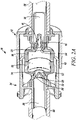
- the second or male connector 24 includes a second or male connector housing 50 that extends annularly about the second deflecting member 30 and the second valve 34, and extends axially outwardly therefrom. As shown in FIGS. 2A through 3 , the second or male connector housing 50 is receivable within the first or female connector housing 48 to interconnect and place the two connectors in fluid communication with each other.
- the second or male connector housing 50 is received within the first or female connector housing 48, and the first and second engaging portions 20, 32 and the first and second valves 22, 34, are located within the second or male connector housing 50.
- the first body 38 of the first connector 12 defines the first ports 16, and the second body 44 of the second connector 24 defines the second ports 28.
- a distal portion 52 of the second body 44 is received within a distal portion 54 of the first body 38 to facilitate aligning the first and second connectors and retaining them in the fully closed position.
- first and second connectors 12, 24 can be releasably connected to each other in any of numerous different ways that are currently known, or that later become known, such as by a threaded connection, snap fit, or other releasable interconnection.
- the first connector 12 includes a plurality of first ports 16 angularly spaced relative to each other
- the second connector 24 includes a plurality of second ports 28 angularly spaced relative to each other.
- a first fluid conduit 56 is connected in fluid communication with the first fluid passageway 14 of the first connector 12
- a second fluid conduit 58 is connected in fluid communication with the second fluid passageway 26 of the second connector 24.
- the ports may take any of numerous different configurations that are currently known, or that later become known.
- each connector may include only one port, more than one port, and/or one connector may have a different number and/or configuration of ports than the other connector.
- one connector may have fewer angularly-elongated ports.
- the first and second connectors may or may not be connected to tubes as shown, but rather may be connected to any of numerous different types of fluid sources, receptacles or devices that are currently known, or that later become known.
- each annular fluid-tight seal 36, 42 extends axially between the respective valve 22, 34 and sealing surface 40, 46 to further prevent the ingress of contaminants through the seal.
- Each sealing surface 40, 46 is relatively rigid, each valve 22, 34 is flexible, and in the closed position, each valve 22, 34 and respective sealing surface 40, 46 form an interference fit therebetween at the respective annular fluid-tight seal 36, 42.
- the first connector includes a first axially and annularly extending base 60 that overlies the first ports 16.
- a first annular, deflectable joint 62 extends between the first base 60 and first valve 22 to facilitate movement of the first valve 22 between the closed and open positions.
- the first body 38 defines an annular and axially-extending first base surface 64 that is formed contiguous to the first ports 16, and a first step 66 extending between the base surface 64 and first sealing surface 40.
- the first step 66 is oriented substantially normal the first base surface 64 and first sealing surface 40.
- the second connector 24 includes a second axially and annularly extending base 68 that overlies the second ports 28, A second annular, deflectable joint 70 extends between the second base 68 and second valve 34 to facilitate movement of the second valve 34 between the closed and open positions.
- the second body 44 defines an annular and axially-extending second base surface 72 that is formed contiguous to the second ports 28 and a second step 74 extending between the base surface 72 and the second sealing surface 46.
- the second step 74 is oriented substantially normal the second base surface 72 and second sealing surface 46.
- the first base 60 sealingly engages the first base 64 of the first valve body 38 to form a fluid-tight seal therebetween, the first step 64 is received within, and sealingly engages the first step 66 of the first body 38 to further effectuate a fluid-tight seal, and the first valve 22 sealingly engages the first sealing surface 40 to effectuate the fluid-tight seal between the valve and body.
- the second base 68 sealingly engages the second base 72 of the second valve body 44 to form a fluid-tight seal therebetween
- the second step 70 is received within, and sealingly engages the second step 74 of the second body 44 to further effectuate a fluid-tight seal
- the second valve 34 sealingly engages the second sealing surface 46 to effectuate the fluid-tight seal between the valve and body.
- all external fluid-contacting surfaces of the first connector body 38 and second connector body 44 are hermetically sealed within the first and second valves 22 and 34, respectively.
- valves 22, 34 are deflected or invaginated into the fully open position into engagement with each other, and thus moved radially away from the respective sealing surfaces 40, 46, the deflecting joints 62, 70 are deflected radially away from the respective steps 64, 72, and the bases 60, 68 are deflected radially away from the respective body base surfaces 64, 72, to thereby define an annulary, axially-extending fluid passageway 76 extending between the two connectors. As indicated by the broken line arrows in FIG.
- fluid in the connected, fully open position, fluid is permitted to flow from the first fluid passageway 14, through the plurality of ports 16, through the annular, axially-extending passageway 76, through the plurality of second ports 28, and into the second passageway 26. If desired, the fluid may flow in the opposite direction.
- the annular, axially-extending passageway 76 is hermetically sealed with respect to both the deflectable ring of concern (i.e., the surfaces of the deflecting members 18, 30) and ambient atmosphere by abutting engagement of the first and second valves 22, 34. As can be seen, the fluid passing between the two connectors is maintained sealed with respect to ambient atmosphere, and the surfaces of the connectors that contact such fluid likewise are sealed with respect to ambient atmosphere to thereby maintain the fluid sterile and hermetically sealed with respect to ambient atmosphere.
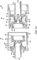
- FIG. 4A another embodiment of a connector of the present invention is indicated generally by the reference numeral 110.
- the connector 110 is substantially the same as the connector 10 described above, and therefore like reference numerals preceded by the numeral "1" are used to indicate like elements.
- the primary difference of the connector 110 in comparison to connector 10 is that it includes first and second supports 180, 182 located between the bases of the first and second housings 148, 150 and the first and second valves 122, 134, respectively.
- the first and second supports 180, 182 may be molded with the bases of the first and second integral valves 122, 134, respectively.
- the first and second supports are co-molded or overmolded with the first and second integral valves 122, 134.
- the first and second supports 180, 182 are snap fit into first and second recesses 186, 188, respectively, provided in the bases of the first and second housings 148, 150, respectively.
- the supports 180, 182 are ring-shaped; however, as may be recognized by those of ordinary skill in the pertinent art, they may take any of numerous different shapes and/or configurations that are currently known or later become known.
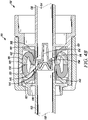
- FIG. 4B is a cross-sectional view of the connector of FIG. 4A showing full interconnection of the male and female connectors.
- the first and second supports 180, 182 bolster the base of the first and second integral valves 122, 134 and increase the structural integrity and durability of the connector 110 in the open position.
- the first and second supports 180, 182 abut the integral valves 122, 134 to prevent failure of the valves.
- Another embodiment of the first and second supports 180, 182 is that they prevent the first and second integral valves 122, 134 from bending or deforming beyond a maximum, open or deflected position.
- the connectors of the present invention have numerous different applications in any of numerous different fields.
- the connectors may be used to interconnect IV tubing, pouches and tubing, filling tanks and/or filling machines, and any of numerous other applications requiring fluid connections.
- the connectors of the present invention are particularly well suited for applications requiring an aseptic or sterile connection, or applications that require the prevention of any contact with the fluid being transferred (such as a toxic fluid).
- the ports, valves, engaging portions, deflecting members, connector bodies, connector housings and means for releasably or otherwise connecting the connectors may take any of numerous different configurations that are currently known, or that later become known.
- the ports, valves, engaging portions, deflecting members, connector bodies, connector housings and means for releasably or otherwise connecting the connectors may take any of numerous different configurations that are currently known, or that later become known.
- not all elements or all features disclosed herein are necessary, and if desired, additional elements or features may be added.
- the elements or components of the connectors may be made of any of numerous different materials that are currently known, or that later become known.
- the connectors may be used to transport any of numerous different fluids that are currently known, or that later become known, such as drugs, pharmaceuticals, vaccines, ophthalmic products, creams, ointments, gels, beverages or food products, such as dairy, milk, cream, infant formula, chocolate, and industrial products, such as industrial liquids or gases. Accordingly, this detailed description of the currently preferred embodiments is to be taken in an illustrative, as opposed to a limiting sense.
Landscapes
- Health & Medical Sciences (AREA)
- Heart & Thoracic Surgery (AREA)
- Engineering & Computer Science (AREA)
- Animal Behavior & Ethology (AREA)
- Public Health (AREA)
- Biomedical Technology (AREA)
- Hematology (AREA)
- Life Sciences & Earth Sciences (AREA)
- Veterinary Medicine (AREA)
- General Health & Medical Sciences (AREA)
- Anesthesiology (AREA)
- Pulmonology (AREA)
- General Engineering & Computer Science (AREA)
- Epidemiology (AREA)
- Mechanical Engineering (AREA)
- Quick-Acting Or Multi-Walled Pipe Joints (AREA)
- Infusion, Injection, And Reservoir Apparatuses (AREA)
- External Artificial Organs (AREA)
Claims (15)
- Aseptischer Fluidverbinder (10, 110), umfassend:einen ersten Verbinder (12, 120), der aufweist:einen ersten Fluiddurchgang (14, 114) zum Aufnehmen eines Fluids darin;einen ersten Port (16, 116) in Fluidverbindung mit dem ersten Fluiddurchgang (14, 114) zum Hindurchleiten des Fluids durch diesen;wobei der aseptische Fluidverbinder ferner umfasst:
einen zweiten Verbinder (24, 124), der mit dem ersten Verbinder (12, 120) verbunden werden kann und aufweist:einen zweiten Fluiddurchgang (26, 126) zum Aufnehmen eines Fluids darin; undeinen zweiten Port (28) in Fluidverbindung mit dem zweiten Fluiddurchgang (26, 126) zum Hindurchleiten des Fluids durch diesen;wobei der erste Fluidverbinder ein erstes Ablenkelement (18, 118) aufweist, das einen ersten Eingriffsabschnitt (20, 120), der relativ zu dem ersten Port (16, 116) radial beabstandet ist, und ein erstes Ventil (22, 122) aufweist, das zwischen einer geschlossenen Position und einer offenen Position mit einer Bewegung des ersten Eingriffsabschnitts (20, 120) jeweils zwischen einer im Wesentlichen nicht abgelenkten Position und einer abgelenkten Position bewegbar ist, wobei das erste Ventil (22, 122) in der im Wesentlichen nicht abgelenkten Position in der geschlossenen Position angeordnet ist und eine fluiddichte Abdichtung zwischen dem ersten Ventil (22, 122) und dem ersten Port (16, 116) bildet und das Hindurchleiten von Fluid durch diesen verhindert, und wobei alle mit Fluid in Kontakt stehenden Flächen des ersten Ports hermetisch abgedichtet sind in Bezug auf die Umgebungsatmosphäre, um eine externe Kontamination der genannten Flächen zu verhindern, und wobei in der abgelenkten Position das erste Ventil (22, 122) in der offenen Position angeordnet ist, die das aseptische Hindurchleiten von Fluid durch den ersten Port (16, 116) gestattet; undwobei der zweite Verbinder ferner ein zweites Ablenkelement (30, 130) aufweist, das aufweist:
einen zweiten Eingriffsabschnitt (32, 132), der relativ zu dem zweiten Port (28) radial beabstandet ist, und ein zweites Ventil (34, 134), das zwischen einer geschlossenen Position und einer offenen Position mit einer Bewegung des zweiten Eingriffsabschnitts (32, 132) jeweils zwischen einer im Wesentlichen nicht abgelenkten Position und einer abgelenkten Position bewegbar ist, wobei in der im Wesentlichen nicht abgelenkten Position das zweite Ventil (34, 134) in der geschlossenen Position angeordnet ist und eine fluiddichte Abdichtung zwischen dem zweiten Ventil (34, 134) und dem zweiten Port (28) bildet und das Hindurchleiten von Fluid durch diesen verhindert, und wobei alle mit Fluid in Kontakt stehenden Flächen des zweiten Ports hermetisch abgedichtet sind in Bezug auf die Umgebungsatmosphäre, um eine externe Kontamination der genannten Flächen zu verhindern, und wobei das zweite Ventil (34, 134) in der offenen Position angeordnet ist, die das Hindurchleiten von Fluid durch den zweiten Port (28) gestattet. - Aseptischer Fluidverbinder (10, 110) nach Anspruch 1, wobei der erste und zweite Verbinder (12, 120, 24, 124) zwischen einer nicht verbundenen und einer verbundenen Position bewegbar sind, wobei sich in der nicht verbundenen Position der erste und zweite Eingriffsabschnitt (20, 120, 32, 132) in den im Wesentlichen nicht abgelenkten Positionen befinden und sich das erste und das zweite Ventil (22, 122, 34, 134) in den geschlossenen Positionen befinden, die das Hindurchleiten von Fluid jeweils durch den ersten und zweiten Port (16, 116, 28) verhindern, und wobei sich in der verbundenen Position der erste und zweite Eingriffsabschnitt (20, 120, 32, 132) in den abgelenkten Positionen befinden und sich das erste und zweite Ventil (22, 122, 34, 134) in der offenen Position befinden.
- Aseptischer Fluiderbinder (10, 110) nach Anspruch 1 oder 2, wobei:
der erste Verbinder (12, 120) ferner einen ersten Körper (38, 138) aufweist, der eine erste Dichtfläche (40, 140) definiert, die benachbart zu dem ersten Port (16, 116) gebildet ist und in der geschlossenen Position mit dem ersten Ventil (22, 122) in Eingriff bringbar ist, um eine fluiddichte Abdichtung zwischen dem ersten Ventil (22, 122) und dem ersten Port (16, 116) zu bilden; der zweite Verbinder (24, 124) ferner einen zweiten Körper (44, 144) aufweist, der eine zweite Dichtfläche (46, 146) definiert, die benachbart zu dem zweiten Port (28) gebildet ist und in der geschlossenen Position mit dem zweiten Ventil (34, 134) in Eingriff bringbar ist, um eine fluiddichte Abdichtung zwischen dem zweiten Ventil (34, 134) und dem zweiten Port (28) zu bilden, wobei vorzugsweise die erste Dichtfläche (40, 140) im Wesentlichen ringförmig ist, wobei das erste Ventil (22, 122) im Wesentlichen ringförmig ist, und in der geschlossenen Position das erste Ventil (22, 122) mit der ersten Dichtfläche (40, 140) in Eingriff steht und eine ringförmige fluiddichte Abdichtung dazwischen bildet; und wobei die zweite Dichtfläche (46, 146) im Wesentlichen ringförmig ist, wobei das zweite Ventil (34, 134) im Wesentlichen ringförmig ist, und in der geschlossenen Position das zweite Ventil (34, 134) mit der zweiten Dichtfläche (46, 146) in Eingriff steht und eine ringförmige fluiddichte Abdichtung dazwischen bildet. - Aseptischer Fluidverbinder (10, 110) nach Anspruch 3, wobei:sich jede ringförmige fluiddichte Dichtung axial zwischen dem jeweiligen Ventil und der Dichtfläche erstreckt, um das Eindringen von Verunreinigungen durch die Dichtung weiter zu verhindern,die erste Dichtfläche (40, 140) relativ starr ist, das erste Ventil (22, 122) flexibel ist, und in der geschlossenen Position das erste Ventil (22, 122) und die erste Dichtfläche (40, 140) dazwischen an der jeweiligen ringförmigen fluiddichten Dichtung eine Presspassung bilden; und die zweite Dichtfläche (46, 146) relativ starr ist, das zweite Ventil (34, 134) flexibel ist, und in der geschlossenen Position das zweite Ventil (34, 134) und die zweite Dichtfläche (46, 146) dazwischen an der jeweiligen ringförmigen fluiddichten Dichtung eine Presspassung bilden, undder erste Eingriffsabschnitt (20, 120) einteilig mit dem ersten Ventil (22, 122) gebildet ist, relativ zu dem ersten Ventil (22, 122) radial beabstandet ist, sich ringförmig um das erste Ventil (22, 122) erstreckt und sich axial relativ zu dem ersten Ventil (22, 122) erstreckt; und der zweite Eingriffsabschnitt (32, 132) einteilig mit dem zweiten Ventil (34, 134) gebildet ist, relativ zu dem zweiten Ventil (34, 134) radial beabstandet ist, sich ringförmig um das zweite Ventil (34, 134) erstreckt und sich axial relativ zu dem zweiten Ventil (34, 134) erstreckt.
- Aseptischer Fluidverbinder (10, 110) nach einem der Ansprüche 2 bis 4, wobei in der verbundenen Position der erste und zweite Eingriffsabschnitt (20, 120, 32, 132) jeweils miteinander in Eingriff stehen und einander in die abgelenkten Positionen ablenken, und wobei das erste und zweite Ventil (22, 122, 34, 134) innerhalb des ersten und zweiten Eingriffsabschnitts (20, 120, 32, 132) in ihren jeweiligen offenen Positionen eingestülpt sind, wobei der erste und zweite Port (16, 116, 28) miteinander in Fluidverbindung stehen, und es gestattet wird, dass Fluid dazwischen fließt.
- Aseptischer Fluidverbinder (10, 110) nach einem der Ansprüche 2 bis 5, wobei sich in der verbundenen Position der erste und zweite Eingriffsabschnitt (20, 120, 32, 132) ringförmig jeweils um das erste und zweite Ventil (22, 122, 34, 134) und den ersten und zweiten Port (16, 116, 28) erstrecken und eine im Wesentlichen fluiddichte Abdichtung in Bezug auf die Umgebungsatmosphäre dazwischen bilden, und wobei sich das erste und das zweite Ventil (22, 122, 34, 134) ringförmig jeweils um den ersten und zweiten Port (16, 116, 28) erstrecken, eine im Wesentlichen fluiddichte Abdichtung in Bezug auf die Umgebungsatmosphäre bilden und eine Kontamination von irgendwelchen mit Fluid in Kontakt stehenden Flächen des ersten und zweiten Ports (16, 116, 28) verhindern.
- Aseptischer Fluidverbinder (10, 110) nach einem der Ansprüche 1 bis 2 oder 5, wobei:eines von dem ersten und/oder dem zweiten Ablenkelement (18, 118, 30, 130) im Wesentlichen kuppelförmig ist, und das erste und/oder das zweite Ablenkelement (18, 118, 30, 130) im Wesentlichen zylinderförmig ist;sich das erste und/oder das zweite Ablenkelement (18, 118, 30, 130) ringförmig um den jeweiligen ersten und/oder zweiten Port (16, 116, 28) erstrecken; undvorzugsweise das erste und/oder zweite Ablenkelement (18, 118, 30, 130) aus einem elastischen Material hergestellt ist.
- Aseptischer Fluidverbinder (10, 110) nach einem der Ansprüche 1 bis 7, wobei der erste Verbinder (12, 120) ein erstes Verbindergehäuse (48, 148) aufweist, das sich ringförmig um den ersten Fluiddurchgang (14, 114) und das erste Element erstreckt und sich davon axial nach außen erstreckt, und wobei der zweite Verbinder (24, 124) ein zweites Verbindergehäuse (50, 150) aufweist, das sich ringförmig um den zweiten Fluiddurchgang (26, 126) und das zweite Element erstreckt und sich davon axial nach außen erstreckt, und
wobei einer von dem ersten und zweiten Verbinder (12, 120, 24, 124) ein weiblicher Verbinder ist, und der anderen von dem ersten und zweiten Verbinder (12, 120, 24, 124) ein männlicher Verbinder ist, der innerhalb des weiblichen Verbinders in der verbundenen Position aufgenommen wird, wobei das Gehäuse des männlichen Verbinders innerhalb des Gehäuses des weiblichen Verbinders in der verbundenen Position aufgenommen werden kann, und wobei vorzugsweise der erste und zweite Eingriffsabschnitt (20, 120, 32, 132) und das erste und zweite Ventil (22, 122, 34, 134) innerhalb des Gehäuses des männlichen Verbinders angeordnet sind. - Aseptischer Fluidverbinder (10, 110) nach einem der Ansprüche 1, 2 oder 4 bis 8, wobei der erste Verbinder (12, 120) einen ersten Körper (38, 138) aufweist, der den ersten Port (16, 116) definiert, wobei der zweite Verbinder (24, 124) einen zweiten Körper (44, 144) aufweist, der den zweiten Port (28) definiert, und wobei vorzugsweise der erste Verbinder (12, 120) eine Vielzahl von ersten Ports aufweist, die winkelmäßig relativ zueinander beabstandet sind, und wobei der zweite Verbinder (24, 124) eine Vielzahl von zweiten Ports aufweist, die winkelmäßig relativ zueinander beabstandet sind, und wobei in der geschlossenen Position ein distaler Abschnitt des zweiten Körpers (44, 144) innerhalb eines distalen Abschnitts des ersten Körpers (38, 138) aufgenommen wird.
- Aseptischer Fluidverbinder (10, 110) nach einem der Ansprüche 2 bis 8, wobei in der verbundenen Position der erste Fluiddurchgang (14, 114), der erste Port (16, 116), der zweite Port (28) und der zweite Fluiddurchgang (26, 126) einen aseptischen Fluiddurchgang definieren, der in Bezug auf die Umgebungsatmosphäre für einen aseptischen Durchgang von Fluid zwischen dem ersten und zweiten Verbinder (12, 120, 24, 124) abgedichtet ist.
- Aseptischer Fluidverbinder (10, 110) nach einem der Ansprüche 1 bis 10, wobei der erste Verbinder (12, 120) ein zweites Verbindereingriffsende definiert, und wobei alle mit Fluid in Kontakt stehenden Flächen des zweiten Verbindereingriffsendes hermetisch in Bezug auf die Umgebungsatmosphäre abgedichtet sind, um eine externe Kontamination der genannten Flächen zu verhindern, und wobei der zweite Verbinder (24, 124) ein erstes Verbindereingriffsende definiert, und wobei alle mit Fluid in Kontakt stehenden Flächen des ersten Verbindereingriffsendes hermetisch in Bezug auf die Umgebungsatmosphäre abgedichtet sind, um eine externe Kontamination der genannten Flächen zu verhindern.
- Aseptischer Fluidverbinder (10, 110) nach einem der Ansprüche 1 bis 11, wobei der zweite Eingriffsabschnitt (32, 132) in der im Wesentlichen nicht abgelenkten Position ein geschlossenes Ventil definiert, welches das Hindurchleiten von Fluid durch den zweiten Port (28) verhindert, und wobei der zweite Eingriffsabschnitt (32, 132) in der abgelenkten Position ein offenes Ventil definiert, welches das aseptische Hindurchleiten von Fluid durch den zweiten Port (28) gestattet.
- Verfahren, umfassend die folgenden Schritte:i. Bereitstellen eines aseptischen Fluidverbinders (10, 110), wie in einem der vorhergehenden Ansprüche definiert, wobei der aseptische Fluidverbinder einen ersten Verbinder (12, 120) umfasst, der ein erstes Ventil (22, 122) aufweist, das hermetisch in einer normalerweise geschlossenen Position einen ersten Port (16, 116) in Fluidverbindung mit einem ersten Fluiddurchgang (14, 114) und ein steriles Fluid in Fluidverbindung mit dem ersten Fluiddurchgang abdichtet;ii. Verbinden des ersten Verbinders (12, 120) mit einem zweiten Verbinder (24, 124), der einen zweiten Port in Fluidverbindung mit einem zweiten Fluiddurchgang (26, 126) aufweist;iii. während des Verbindungsschritts, Ablenken des ersten Ventils (22, 122) von der normalerweise geschlossenen Position in eine offene Position, und Versetzen des ersten Ports (16, 116) in Fluidverbindung mit dem zweiten Port (28);iv. Zulassen eines Stroms von sterilem Fluid durch den ersten und zweiten Port (16, 116, 28); undv. während der vorhergehenden Schritte, Halten des ersten und zweiten Ports (16, 116, 28) in Bezug auf die Umgebungsatmosphäre hermetisch abgedichtet, und Verhindern einer Kontamination von irgendwelchen mit Fluid in Kontakt stehenden Flächen des ersten und zweiten Ports (16, 116, 28) und des durch diese hindurchfließenden sterilen Fluids.
- Verfahren nach Anspruch 13, wobei der erste Verbinder (12, 120) ein erstes Ablenkelement (18, 118) aufweist, und wobei der zweite Verbinder (24, 124) ein zweites Ventil (34, 134) und ein zweites Ablenkelement (30, 130) aufweist, und der Schritt des Bewegens umfasst: Versetzen des ersten und/oder des zweiten Ablenkelements (18, 118, 30, 130) in Eingriff mit dem anderen, Ablenken des ersten und zweiten Ablenkelements (18, 118, 30, 130) und seinerseits Bewegen des ersten und zweiten Ventils (22, 122, 34, 134) aus normalerweise geschlossenen Positionen in offene Positionen und Versetzen des ersten und zweiten Ports (16, 116, 28) in Fluidverbindung miteinander, und ferner umfassend den Schritt: Bilden einer fluiddichten Abdichtung, wenn in den verbundenen und offenen Positionen, zwischen dem ersten und zweiten Ablenkelement (18, 118, 30, 130) und/oder dem ersten und zweiten Ventil (22, 122, 34, 134), hermetisches Abdichten des ersten und zweiten Ports (16, 116, 28) in Bezug auf die Umgebungsatmosphäre, und Verhindern einer Kontamination von irgendwelchen mit Fluid in Kontakt stehenden Flächen des ersten und zweiten Ports (16, 116, 28) und des durch diese hindurchfließenden sterilen Fluids.
- Verfahren nach Anspruch 14, wobei während des Verbindungsschritts das erste und zweite Ablenkelement (18, 118, 30, 130) elastisch ineinander eingreifen und das erste und zweite Ventil (22, 122, 34, 134) in die offene Position und in Kontakt miteinander einstülpen, um dazwischen eine ringförmige, fluiddichte Abdichtung zu bilden.
Applications Claiming Priority (2)
| Application Number | Priority Date | Filing Date | Title |
|---|---|---|---|
| US32085710P | 2010-04-05 | 2010-04-05 | |
| PCT/US2011/031280 WO2011127074A1 (en) | 2010-04-05 | 2011-04-05 | Aseptic connector with deflectable ring of concern and method |
Publications (3)
| Publication Number | Publication Date |
|---|---|
| EP2555825A1 EP2555825A1 (de) | 2013-02-13 |
| EP2555825A4 EP2555825A4 (de) | 2015-07-29 |
| EP2555825B1 true EP2555825B1 (de) | 2022-06-22 |
Family
ID=44708234
Family Applications (1)
| Application Number | Title | Priority Date | Filing Date |
|---|---|---|---|
| EP11766604.0A Active EP2555825B1 (de) | 2010-04-05 | 2011-04-05 | Aseptischer fluidverbinder mit ablenkungselementen und verfahren zur verwendung eines solchen verbinders |
Country Status (11)
| Country | Link |
|---|---|
| US (2) | US8671964B2 (de) |
| EP (1) | EP2555825B1 (de) |
| JP (1) | JP6282112B2 (de) |
| KR (1) | KR101540929B1 (de) |
| CN (1) | CN102971040B (de) |
| AU (1) | AU2011237798C1 (de) |
| BR (1) | BR112012025546A2 (de) |
| CA (1) | CA2795728C (de) |
| RU (1) | RU2537781C2 (de) |
| SG (1) | SG184479A1 (de) |
| WO (1) | WO2011127074A1 (de) |
Families Citing this family (104)
| Publication number | Priority date | Publication date | Assignee | Title |
|---|---|---|---|---|
| US20060161115A1 (en) | 2004-11-05 | 2006-07-20 | Fangrow Thomas F | Soft-grip medical connector |
| US7547300B2 (en) | 2006-04-12 | 2009-06-16 | Icu Medical, Inc. | Vial adaptor for regulating pressure |
| AU2009214439B2 (en) * | 2008-02-14 | 2014-09-25 | Solventum Intellectual Properties Company | Devices and methods for treatment of damaged tissue |
| WO2010022095A1 (en) | 2008-08-20 | 2010-02-25 | Icu Medical, Inc. | Anti-reflux vial adaptors |
| US9168366B2 (en) | 2008-12-19 | 2015-10-27 | Icu Medical, Inc. | Medical connector with closeable luer connector |
| US8454579B2 (en) | 2009-03-25 | 2013-06-04 | Icu Medical, Inc. | Medical connector with automatic valves and volume regulator |
| US8323249B2 (en) | 2009-08-14 | 2012-12-04 | The Regents Of The University Of Michigan | Integrated vascular delivery system |
| USD644731S1 (en) | 2010-03-23 | 2011-09-06 | Icu Medical, Inc. | Medical connector |
| JP6282112B2 (ja) * | 2010-04-05 | 2018-02-21 | ダニエル ピーワイ | 懸案の屈曲可能リングを備える無菌コネクタ及び方法 |
| US8758306B2 (en) | 2010-05-17 | 2014-06-24 | Icu Medical, Inc. | Medical connectors and methods of use |
| US8814833B2 (en) | 2010-05-19 | 2014-08-26 | Tangent Medical Technologies Llc | Safety needle system operable with a medical device |
| WO2011146769A2 (en) | 2010-05-19 | 2011-11-24 | Tangent Medical Technologies Llc | Integrated vascular delivery system |
| WO2012145434A1 (en) | 2011-04-18 | 2012-10-26 | Dr. Py Institute, Llc | Needle with closure and method |
| US10773863B2 (en) | 2011-06-22 | 2020-09-15 | Sartorius Stedim North America Inc. | Vessel closures and methods for using and manufacturing same |
| WO2013025946A1 (en) | 2011-08-18 | 2013-02-21 | Icu Medical, Inc. | Pressure-regulating vial adaptors |
| AU2012304344B2 (en) | 2011-09-09 | 2016-02-04 | Icu Medical, Inc. | Medical connectors with fluid-resistant mating interfaces |
| US8535241B2 (en) | 2011-10-13 | 2013-09-17 | Magnolia Medical Technologies, Inc. | Fluid diversion mechanism for bodily-fluid sampling |
| CN103917269B (zh) * | 2011-10-19 | 2016-12-07 | 拜耳医药保健有限公司 | 保持无菌的医用连接器组件和方法 |
| CN104168948B (zh) | 2012-01-13 | 2017-03-01 | Icu医学有限公司 | 控压型管形瓶接头和方法 |
| WO2013142618A1 (en) | 2012-03-22 | 2013-09-26 | Icu Medical, Inc. | Pressure-regulating vial adaptors |
| WO2013158756A1 (en) * | 2012-04-17 | 2013-10-24 | Dr. Py Institute, Llc | Self closing connector |
| US10351271B2 (en) | 2012-05-01 | 2019-07-16 | Dr. Py Institute Llc | Device for connecting or filling and method |
| BR112014027280A2 (pt) * | 2012-05-01 | 2017-06-27 | Py Dr Inst Llc | dispositivo para conexão ou enchimento e método |
| US9022950B2 (en) | 2012-05-30 | 2015-05-05 | Magnolia Medical Technologies, Inc. | Fluid diversion mechanism for bodily-fluid sampling |
| US9060724B2 (en) | 2012-05-30 | 2015-06-23 | Magnolia Medical Technologies, Inc. | Fluid diversion mechanism for bodily-fluid sampling |
| WO2014022275A1 (en) | 2012-08-01 | 2014-02-06 | Magnolia Medical Technologies, Inc. | Fluid diversion mechanism for bodily-fluid sampling |
| WO2014058945A1 (en) | 2012-10-11 | 2014-04-17 | Bullington Gregory J | Systems and methods for delivering a fluid to a patient with reduced contamination |
| AU2013342123B2 (en) | 2012-11-12 | 2018-08-02 | Icu Medical, Inc. | Medical connector |
| CN109171766A (zh) | 2012-11-30 | 2019-01-11 | 木兰医药技术股份有限公司 | 体液隔绝装置和使用体液隔绝装置隔绝体液的方法 |
| IL303591B2 (en) | 2012-12-04 | 2025-11-01 | Magnolia Medical Technologies Inc | Sterile bodily-fluid collection device and methods |
| US10772548B2 (en) | 2012-12-04 | 2020-09-15 | Magnolia Medical Technologies, Inc. | Sterile bodily-fluid collection device and methods |
| GB2509501B (en) * | 2013-01-03 | 2018-05-09 | Intersurgical Ag | Improvements in relation to valves |
| AU2014209594B2 (en) | 2013-01-23 | 2018-09-13 | Icu Medical, Inc. | Pressure-regulating vial adaptors |
| US9089475B2 (en) | 2013-01-23 | 2015-07-28 | Icu Medical, Inc. | Pressure-regulating vial adaptors |
| CN105163796B (zh) | 2013-03-15 | 2018-06-01 | Icu医学有限公司 | 医用连接器 |
| WO2014145313A2 (en) | 2013-03-15 | 2014-09-18 | Dr. Py Institute, Llc | Controlled non-classified filling device and method |
| US9901729B2 (en) * | 2013-03-29 | 2018-02-27 | Emd Millipore Corporation | Sterile connection/disconnection coupling and method |
| JP2016521627A (ja) | 2013-06-14 | 2016-07-25 | バイエル メディカル ケア インコーポレーテッド | 携帯型流体送出システム |
| AU2014290124B2 (en) | 2013-07-19 | 2019-05-09 | Icu Medical, Inc. | Pressure-regulating fluid transfer systems and methods |
| CN104415404B (zh) * | 2013-08-23 | 2017-05-24 | 北京万生人和科技有限公司 | 一种导尿装置 |
| EP3079739B1 (de) | 2013-12-11 | 2023-02-22 | ICU Medical, Inc. | Rückschlagventil |
| US10549084B2 (en) | 2014-01-10 | 2020-02-04 | Bayer Healthcare Llc | Single-use disposable set connector |
| JP6461174B2 (ja) | 2014-02-04 | 2019-01-30 | アイシーユー・メディカル・インコーポレーテッド | 自己プライミングシステムおよび自己プライミング方法 |
| DE202014100585U1 (de) | 2014-02-11 | 2014-04-22 | Heinz Meise Gmbh | Vorrichtung zum sterilen Verbinden von medizinischen Einwegartikeln |
| EP4218708B1 (de) | 2014-03-03 | 2024-12-18 | Magnolia Medical Technologies, Inc. | Vorrichtung zur desinfektion eines probenbehälters |
| CA2953229C (en) | 2014-06-20 | 2024-01-02 | Icu Medical, Inc. | Pressure-regulating vial adaptors |
| USD793551S1 (en) | 2014-12-03 | 2017-08-01 | Icu Medical, Inc. | Fluid manifold |
| USD786427S1 (en) | 2014-12-03 | 2017-05-09 | Icu Medical, Inc. | Fluid manifold |
| ES3030489T3 (en) | 2015-01-09 | 2025-06-30 | Bayer Healthcare Llc | Multiple fluid delivery system with multi-use disposable set and features thereof |
| EP3875824B1 (de) | 2015-04-20 | 2024-10-30 | Colder Products Company | Aseptische einweg-flüssigkeitskupplungen |
| CA2986808A1 (en) * | 2015-06-16 | 2016-12-22 | Juan WALTERSPIEL | Tubing connector for decreased contamination |
| US20200408350A1 (en) | 2015-06-16 | 2020-12-31 | Juan Nepomuc Walterspiel | Tubing connector for decreased contamination |
| EP3733067B1 (de) | 2015-09-03 | 2023-06-14 | Magnolia Medical Technologies, Inc. | System zum aufrechterhalten der sterilität eines probenbehälters |
| CA3002966A1 (en) | 2015-09-15 | 2017-03-23 | Dr. Py Institute Llc | Septum that decontaminates by interaction with penetrating element |
| USD829896S1 (en) | 2015-09-15 | 2018-10-02 | Dr. Py Institute Llc | Septum |
| CN108290034B (zh) * | 2015-10-08 | 2021-03-05 | 考尔得产品公司 | 可再用的无菌流体联接器 |
| JP2019502483A (ja) | 2016-01-19 | 2019-01-31 | ダニエル ピーワイ | 使い捨てコネクタ |
| CA3012733C (en) | 2016-01-29 | 2023-09-12 | Icu Medical, Inc. | Pressure-regulating vial adaptors |
| US10413663B2 (en) * | 2016-03-04 | 2019-09-17 | Zyno Medical, Llc | Automatic anti-free-flow valve for medical pumps |
| CN105879145B (zh) * | 2016-04-01 | 2019-06-18 | 广东省人民医院 | 分隔膜输液接头 |
| DK3471797T3 (da) | 2016-06-15 | 2021-06-14 | Bayer Healthcare Llc | Engangssystem til flere formål og tilknyttet sprøjte |
| JP7063891B2 (ja) | 2016-09-30 | 2022-05-09 | アイシーユー・メディカル・インコーポレーテッド | バイアルアダプタ |
| JP7273807B2 (ja) | 2017-06-09 | 2023-05-15 | マグノリア メディカル テクノロジーズ,インコーポレイテッド | 流体制御デバイス及びそれを使用する方法 |
| EP3681384B1 (de) | 2017-09-12 | 2022-12-28 | Magnolia Medical Technologies, Inc. | Ein system |
| US11633584B2 (en) * | 2017-09-20 | 2023-04-25 | Miltenyi Biotec Gmbh | Sterile connector |
| EP3710361A4 (de) | 2017-11-14 | 2021-08-11 | Sartorius Stedim North America Inc. | Flüssigkeitsübertragungsanordnung mit einem übergang mit mehreren fluidwegen |
| US11319201B2 (en) | 2019-07-23 | 2022-05-03 | Sartorius Stedim North America Inc. | System for simultaneous filling of multiple containers |
| US11691866B2 (en) | 2017-11-14 | 2023-07-04 | Sartorius Stedim North America Inc. | System for simultaneous distribution of fluid to multiple vessels and method of using the same |
| US12252391B2 (en) | 2017-11-14 | 2025-03-18 | Sartorius Stedim North America Inc. | System for simultaneous distribution of fluid to multiple vessels and method of using the same |
| US11577953B2 (en) | 2017-11-14 | 2023-02-14 | Sartorius Stedim North America, Inc. | System for simultaneous distribution of fluid to multiple vessels and method of using the same |
| US11419531B2 (en) | 2017-12-07 | 2022-08-23 | Magnolia Medical Technologies, Inc. | Fluid control devices and methods of using the same |
| US20190323625A1 (en) * | 2018-04-23 | 2019-10-24 | Rain Bird Corporation | Valve With Reinforcement Ports And Manually Removable Scrubber |
| EP3897812A4 (de) * | 2018-12-20 | 2022-11-16 | Centre for Commercialization of Regenerative Medicine | Systeme und verfahren für einen wiederverwendbaren, aseptischen konnektor |
| WO2020163744A1 (en) | 2019-02-08 | 2020-08-13 | Magnolia Medical Technologies, Inc. | Devices and methods for bodily fluid collection and distribution |
| US10413712B1 (en) * | 2019-02-28 | 2019-09-17 | Injectimed, Inc. | Luer-activated valves |
| AU2020234829B2 (en) | 2019-03-11 | 2025-11-13 | Magnolia Medical Technologies, Inc. | Fluid control devices and methods of using the same |
| CN109999333B (zh) * | 2019-04-24 | 2024-05-10 | 华道(上海)生物医药有限公司 | 无菌对接器 |
| CN114615964B (zh) * | 2019-10-31 | 2025-10-28 | 纳卡特尔国际进出口股份责任有限公司 | 重新配制、提取和输注药液的安全组件 |
| EP4084854A4 (de) | 2019-12-31 | 2023-04-19 | Colder Products Company | Aseptische flüssigkeitskupplungen |
| DE102020106212A1 (de) * | 2020-03-06 | 2021-09-09 | Wabco Europe Bvba | Fluidventil, Ventilanordnung und Bremsanlage |
| WO2021183687A2 (en) | 2020-03-10 | 2021-09-16 | Cellares Corporation | Systems, devices, and methods for cell processing |
| US11480281B2 (en) | 2020-06-11 | 2022-10-25 | Colder Products Company | Single-use disconnect fluid couplings |
| WO2022047023A1 (en) | 2020-08-27 | 2022-03-03 | Colder Products Company | Fluid couplings |
| FR3117569B1 (fr) * | 2020-12-16 | 2022-11-25 | Parker Hannifin Emea Sarl | Dispositif de raccordement aseptique d’un tube |
| CA3211283A1 (en) * | 2021-03-15 | 2022-09-22 | Spencer HOOVER | Aseptic connector with disposable air lock |
| KR20220149158A (ko) | 2021-04-30 | 2022-11-08 | 한주리 | 스마트폰 폴라로이드 카메라 |
| WO2022265958A1 (en) * | 2021-06-17 | 2022-12-22 | Colder Products Company | Aseptic fluid couplings |
| US12239127B2 (en) | 2021-07-28 | 2025-03-04 | Sartorius Stedim North America Inc. | Thermal capacitors, systems, and methods for rapid freezing or heating of biological materials |
| WO2023027633A2 (en) | 2021-08-26 | 2023-03-02 | Agency For Science, Technology And Research | Connector component and connector system |
| US12460759B2 (en) * | 2021-10-06 | 2025-11-04 | Nordson Corporation | Aseptic coupling system with seal isolating connectors |
| CN115154885B (zh) * | 2022-08-15 | 2024-05-07 | 无锡耐思生命科技股份有限公司 | 一种无菌连接件和无菌连接装置 |
| US12123526B2 (en) | 2022-09-12 | 2024-10-22 | Avantor Fluid Handling, Llc | Aseptic connect and disconnect coupler |
| US12180453B2 (en) | 2023-03-21 | 2024-12-31 | Cellares Corporation | Systems, devices, and methods for electroporation within a cell processing system |
| EP4704958A1 (de) | 2023-04-25 | 2026-03-11 | WilMarc Holdings, LLC | Geschlechtsloser aseptischer verbinder |
| FR3148277B1 (fr) * | 2023-04-28 | 2025-03-14 | Parker Hannifin Emea Sarl | Dispositif de raccordement aseptique d’un tube |
| US12399193B2 (en) | 2023-05-05 | 2025-08-26 | Cellares Corporation | Systems, devices, and methods for combined cell processes |
| WO2025007051A2 (en) | 2023-06-30 | 2025-01-02 | Cellares Corporation | Systems, devices, and methods for fluid transfer within an automated cell processing system |
| WO2025041064A2 (en) | 2023-08-21 | 2025-02-27 | Cellares Corporation | Systems, devices, and methods for automatic cell sorting |
| US12497587B2 (en) | 2023-08-21 | 2025-12-16 | Cellares Corporation | Bioreactors and methods of their use in automatic cell processing systems |
| US12305156B2 (en) | 2023-08-21 | 2025-05-20 | Cellares Corporation | Systems, devices, and methods for fluid control in a cell processing system |
| USD1105422S1 (en) | 2024-02-09 | 2025-12-09 | Icu Medical, Inc. | Medical connector cover |
| US12492368B2 (en) | 2024-03-11 | 2025-12-09 | Cellares Corporation | Monitoring air pressure within a cell processing system |
| WO2025202944A2 (en) | 2024-03-27 | 2025-10-02 | Cellares Corporation | Liquid level and flow rate detection within a cell processing system |
| USD1109621S1 (en) | 2024-04-15 | 2026-01-20 | Cellares Corporation | Analytical platform for biological material testing |
Citations (2)
| Publication number | Priority date | Publication date | Assignee | Title |
|---|---|---|---|---|
| US5573516A (en) * | 1995-09-18 | 1996-11-12 | Medical Connexions, Inc. | Needleless connector |
| EP0795342A2 (de) * | 1996-03-15 | 1997-09-17 | Becton, Dickinson and Company | Kupplungsstück für einen medizinischen Zugang |
Family Cites Families (80)
| Publication number | Priority date | Publication date | Assignee | Title |
|---|---|---|---|---|
| US3916929A (en) | 1974-08-16 | 1975-11-04 | Scovill Manufacturing Co | Self-sealing break-away fitting |
| DE2817102C2 (de) * | 1978-04-19 | 1985-01-24 | Dr. Eduard Fresenius, Chemisch-pharmazeutische Industrie KG, 6380 Bad Homburg | Anschlußstück für Kunststoffkanülen oder Venenkatheter |
| US4232851A (en) | 1979-02-06 | 1980-11-11 | Textron Inc. | Fluid control valve and liner therefor |
| US5199947A (en) | 1983-01-24 | 1993-04-06 | Icu Medical, Inc. | Method of locking an influent line to a piggyback connector |
| US5281206A (en) | 1983-01-24 | 1994-01-25 | Icu Medical, Inc. | Needle connector with rotatable collar |
| US5344414A (en) | 1983-01-24 | 1994-09-06 | Icu Medical Inc. | Medical connector |
| US4752292A (en) | 1983-01-24 | 1988-06-21 | Icu Medical, Inc. | Medical connector |
| US4673400A (en) * | 1986-02-10 | 1987-06-16 | Martin Ivan W | Aseptic connector assembly for conduits for sterile fluids |
| US4931048A (en) | 1986-04-07 | 1990-06-05 | Icu Medical, Inc. | Medical device |
| US4778453A (en) | 1986-04-07 | 1988-10-18 | Icu Medical, Inc. | Medical device |
| US4790832A (en) | 1986-06-06 | 1988-12-13 | Icu Medical, Inc. | System for administering medication nasally to a patient |
| US4709725A (en) | 1987-02-17 | 1987-12-01 | Vetco Gray, Inc. | Metal-to-metal seal structure |
| US4816024A (en) | 1987-04-13 | 1989-03-28 | Icu Medical, Inc. | Medical device |
| US4846805A (en) | 1987-12-04 | 1989-07-11 | Icu Medical, Inc. | Catheter insert device |
| US4842591A (en) * | 1988-01-21 | 1989-06-27 | Luther Ronald B | Connector with one-way septum valve, and assembly |
| US4941517A (en) * | 1988-10-20 | 1990-07-17 | Galloway Trust | Aseptic fluid transfer apparatus and methods |
| US5695466A (en) | 1993-07-23 | 1997-12-09 | Icu Medical, Inc. | Medical connection indicator and method of use |
| DK0988871T3 (da) | 1991-12-18 | 2004-05-24 | Icu Medical Inc | Fremgangsmåde til overføring af fluid |
| US5694686A (en) | 1991-12-18 | 1997-12-09 | Icu Medical, Inc. | Method for assembling a medical valve |
| DE69528063T2 (de) | 1994-06-24 | 2003-06-05 | Icu Medical, Inc. | Vorrichtung zur überleitung einer flüssigkeit und methode zur anwendung |
| US5492147A (en) * | 1995-01-17 | 1996-02-20 | Aeroquip Corporation | Dry break coupling |
| US5810768A (en) | 1995-06-07 | 1998-09-22 | Icu Medical, Inc. | Medical connector |
| US5700248A (en) | 1995-12-15 | 1997-12-23 | Icu Medical, Inc. | Medical valve with tire seal |
| US5738663A (en) | 1995-12-15 | 1998-04-14 | Icu Medical, Inc. | Medical valve with fluid escape space |
| US5810792A (en) | 1996-04-03 | 1998-09-22 | Icu Medical, Inc. | Locking blunt cannula |
| US5791376A (en) | 1996-05-16 | 1998-08-11 | Mega Systems & Chemicals, Inc. | Quick disconnect valve system for abrasive slurries |
| PT952868E (pt) * | 1996-11-18 | 2004-08-31 | Nypro Inc | Valvula conica-luer lavavel |
| US6245048B1 (en) | 1996-12-16 | 2001-06-12 | Icu Medical, Inc. | Medical valve with positive flow characteristics |
| EP0956088B1 (de) | 1996-12-16 | 2010-07-28 | ICU Medical, Inc. | Positives durchflussventil |
| US5878798A (en) | 1997-02-28 | 1999-03-09 | Eastman Kodak Company | Valve system |
| EP1716885A3 (de) | 1997-05-09 | 2006-11-15 | Pall Corporation | Verbindungsanordnungen, Fluidsysteme und Methoden zum Erstellen einer Verbindung |
| US6039718A (en) * | 1998-01-20 | 2000-03-21 | Bracco Research Usa | Multiple use universal connector |
| US6726672B1 (en) | 1998-09-28 | 2004-04-27 | Icu Medical, Inc. | Intravenous drug access system |
| US6706022B1 (en) * | 1999-07-27 | 2004-03-16 | Alaris Medical Systems, Inc. | Needleless medical connector with expandable valve mechanism |
| KR100755567B1 (ko) | 1999-12-14 | 2007-09-06 | 아이씨유 메디칼 인코퍼레이티드 | 다수 부품 디바이스를 제조하는 방법 |
| US6793651B1 (en) | 2000-02-23 | 2004-09-21 | Icu Medical, Inc. | Urinary catheter system with a releasable connector |
| EP1305225A4 (de) | 2000-06-21 | 2003-08-27 | Paul Francois Roos | Selbstschliessende kupplung |
| US6695817B1 (en) * | 2000-07-11 | 2004-02-24 | Icu Medical, Inc. | Medical valve with positive flow characteristics |
| US6837878B2 (en) | 2001-01-09 | 2005-01-04 | Icu Medical, Inc. | Bluntable needle assembly with open-ended blunting probe |
| WO2002070037A2 (en) | 2001-03-04 | 2002-09-12 | Sterling Medivations, Inc. | Infusion hub assembly and fluid line disconnect system |
| US6581641B2 (en) * | 2001-04-05 | 2003-06-24 | Illinois Tool Works Inc. | One-way valve for use with vacuum pump |
| US6651955B2 (en) * | 2001-07-30 | 2003-11-25 | Hewlett-Packard Development Company, L.P. | Elastomeric valve, and methods |
| US6679529B2 (en) | 2001-08-06 | 2004-01-20 | Theodore D. Johnson | Connection system |
| WO2003018104A2 (en) * | 2001-08-22 | 2003-03-06 | Nypro, Inc. | Medical valve with expandable seal member |
| US6908459B2 (en) * | 2001-12-07 | 2005-06-21 | Becton, Dickinson And Company | Needleless luer access connector |
| US6874522B2 (en) * | 2002-06-18 | 2005-04-05 | Baxter International Inc. | Luer-actuated solution path connector with membrane and container using the connector and a method for establishing fluid communication with the container |
| JP4430537B2 (ja) | 2002-07-26 | 2010-03-10 | ミリポア・コーポレイション | 滅菌コネクタ |
| JP2004195016A (ja) * | 2002-12-19 | 2004-07-15 | Top:Kk | 継ぎ手装置 |
| US7658205B1 (en) | 2002-12-19 | 2010-02-09 | Vitalwear, Inc. | Systems for a fluid circuit coupler |
| JP4432339B2 (ja) * | 2003-03-17 | 2010-03-17 | ニプロ株式会社 | 医療用弁 |
| US7040598B2 (en) * | 2003-05-14 | 2006-05-09 | Cardinal Health 303, Inc. | Self-sealing male connector |
| US7156826B2 (en) | 2003-05-23 | 2007-01-02 | Icu Medical, Inc. | Medical connector and method for nasally administering or removing a substance |
| US20050015075A1 (en) * | 2003-07-14 | 2005-01-20 | B & D Research And Development Inc. | Coupling device for medical lines |
| US7309326B2 (en) | 2003-11-18 | 2007-12-18 | Icu Medical, Inc. | Infusion set |
| HK1077154A2 (en) | 2003-12-30 | 2006-02-03 | Icu Medical, Inc. | Valve assembly |
| RU44511U1 (ru) * | 2004-09-27 | 2005-03-27 | Государственное учреждение Самарский государственный медицинский университет | Устройство для эндоваскулярных операций |
| US7296782B2 (en) * | 2004-10-01 | 2007-11-20 | Halkey-Roberts Corporation | Dome check valve |
| US20060161115A1 (en) | 2004-11-05 | 2006-07-20 | Fangrow Thomas F | Soft-grip medical connector |
| US7396051B2 (en) * | 2005-01-14 | 2008-07-08 | Baxa Corporation | Swabable fluid connectors and fluid connector pairs |
| US7670322B2 (en) | 2005-02-01 | 2010-03-02 | Icu Medical, Inc. | Check valve for medical Y-site |
| DE102005020648A1 (de) | 2005-05-03 | 2006-11-16 | Sartorius Ag | Verbinder, Verbindersystem und Verwendung |
| US20070088292A1 (en) | 2005-07-06 | 2007-04-19 | Fangrow Thomas F Jr | Medical connector with closeable male luer |
| US7892216B2 (en) | 2006-02-07 | 2011-02-22 | Icu Medical, Inc. | Infusion set |
| US7547300B2 (en) | 2006-04-12 | 2009-06-16 | Icu Medical, Inc. | Vial adaptor for regulating pressure |
| US7753338B2 (en) * | 2006-10-23 | 2010-07-13 | Baxter International Inc. | Luer activated device with minimal fluid displacement |
| AU2007308835A1 (en) | 2006-10-25 | 2008-05-02 | Icu Medical, Inc. | Medical connector |
| CN101626803B (zh) | 2007-02-01 | 2013-08-21 | 圣戈本操作塑料有限公司 | 连接器组件 |
| US7883499B2 (en) | 2007-03-09 | 2011-02-08 | Icu Medical, Inc. | Vial adaptors and vials for regulating pressure |
| ES2381230T3 (es) | 2007-03-09 | 2012-05-24 | Basf Se | Antioxidantes similares a cumestano y absorbentes uv |
| JP5520927B2 (ja) * | 2008-03-25 | 2014-06-11 | サン−ゴバン パフォーマンス プラスティックス コーポレイション | コネクタアセンブリ |
| US20090243281A1 (en) | 2008-03-28 | 2009-10-01 | Icu Medical Inc. | Connectors having features to facilitate or hamper tightening and/or loosening |
| US7959192B2 (en) | 2008-07-09 | 2011-06-14 | Pall Corporation | Disconnectable connector assembly |
| FR2934337B1 (fr) * | 2008-07-23 | 2010-09-17 | Millipore Corp | Dispositifs de raccordement et systeme de raccordement male-femelle les comportant |
| WO2010022095A1 (en) | 2008-08-20 | 2010-02-25 | Icu Medical, Inc. | Anti-reflux vial adaptors |
| US8679090B2 (en) | 2008-12-19 | 2014-03-25 | Icu Medical, Inc. | Medical connector with closeable luer connector |
| US8454579B2 (en) | 2009-03-25 | 2013-06-04 | Icu Medical, Inc. | Medical connector with automatic valves and volume regulator |
| AU2010276522B2 (en) | 2009-07-29 | 2016-03-10 | Icu Medical, Inc. | Fluid transfer devices and methods of use |
| JP6282112B2 (ja) * | 2010-04-05 | 2018-02-21 | ダニエル ピーワイ | 懸案の屈曲可能リングを備える無菌コネクタ及び方法 |
| ES2493515T3 (es) | 2010-05-06 | 2014-09-11 | Icu Medical, Inc. | Conector médico con conexión tipo Luer obturable |
| US8758306B2 (en) | 2010-05-17 | 2014-06-24 | Icu Medical, Inc. | Medical connectors and methods of use |
-
2011
- 2011-04-05 JP JP2013503849A patent/JP6282112B2/ja active Active
- 2011-04-05 AU AU2011237798A patent/AU2011237798C1/en not_active Ceased
- 2011-04-05 SG SG2012074415A patent/SG184479A1/en unknown
- 2011-04-05 CA CA2795728A patent/CA2795728C/en not_active Expired - Fee Related
- 2011-04-05 KR KR1020127028651A patent/KR101540929B1/ko not_active Expired - Fee Related
- 2011-04-05 BR BR112012025546A patent/BR112012025546A2/pt not_active Application Discontinuation
- 2011-04-05 CN CN201180023198.XA patent/CN102971040B/zh active Active
- 2011-04-05 WO PCT/US2011/031280 patent/WO2011127074A1/en not_active Ceased
- 2011-04-05 EP EP11766604.0A patent/EP2555825B1/de active Active
- 2011-04-05 US US13/080,537 patent/US8671964B2/en active Active
- 2011-04-05 RU RU2012146979/14A patent/RU2537781C2/ru not_active IP Right Cessation
-
2014
- 2014-03-18 US US14/217,864 patent/US9726314B2/en active Active
Patent Citations (2)
| Publication number | Priority date | Publication date | Assignee | Title |
|---|---|---|---|---|
| US5573516A (en) * | 1995-09-18 | 1996-11-12 | Medical Connexions, Inc. | Needleless connector |
| EP0795342A2 (de) * | 1996-03-15 | 1997-09-17 | Becton, Dickinson and Company | Kupplungsstück für einen medizinischen Zugang |
Also Published As
| Publication number | Publication date |
|---|---|
| SG184479A1 (en) | 2012-11-29 |
| CN102971040B (zh) | 2016-09-07 |
| AU2011237798C1 (en) | 2014-12-11 |
| RU2012146979A (ru) | 2014-05-20 |
| US20140290770A1 (en) | 2014-10-02 |
| EP2555825A1 (de) | 2013-02-13 |
| CA2795728A1 (en) | 2011-10-13 |
| BR112012025546A2 (pt) | 2016-06-28 |
| JP6282112B2 (ja) | 2018-02-21 |
| US8671964B2 (en) | 2014-03-18 |
| AU2011237798A1 (en) | 2012-11-08 |
| US20110240158A1 (en) | 2011-10-06 |
| JP2013523337A (ja) | 2013-06-17 |
| CN102971040A (zh) | 2013-03-13 |
| WO2011127074A1 (en) | 2011-10-13 |
| AU2011237798B2 (en) | 2014-06-26 |
| CA2795728C (en) | 2015-06-09 |
| KR20130018286A (ko) | 2013-02-20 |
| US9726314B2 (en) | 2017-08-08 |
| KR101540929B1 (ko) | 2015-08-03 |
| RU2537781C2 (ru) | 2015-01-10 |
| EP2555825A4 (de) | 2015-07-29 |
Similar Documents
| Publication | Publication Date | Title |
|---|---|---|
| EP2555825B1 (de) | Aseptischer fluidverbinder mit ablenkungselementen und verfahren zur verwendung eines solchen verbinders | |
| US8746278B2 (en) | Connector and related method | |
| EP2024673B1 (de) | Aseptische kupplungsvorrichtungen | |
| EP2271398B1 (de) | Verbinderanordnung | |
| EP4288686B1 (de) | Flüssigkeitskupplungsvorrichtung und verfahren zum kuppeln einer flüssigkeitskupplung | |
| JP5000639B2 (ja) | コネクタ、コネクタシステムおよびその使用 | |
| US8585099B2 (en) | Sanitary coupling assembly | |
| CN116576318B (zh) | 一种无菌连接装置、对接器、系统及连接方法 | |
| US10173044B2 (en) | Locking taper fluid connection interfaces | |
| CN109519616B (zh) | 无菌连接器 | |
| WO2011125023A1 (en) | Connection device and connection system comprising it | |
| HK1183252A (en) | Aseptic connector with deflectable ring of concern and method | |
| EP4153895B1 (de) | Schlauchverbinder | |
| WO2019070389A2 (en) | CONNECTOR ASSEMBLY, CONNECTORS THEREFOR, AND METHOD |
Legal Events
| Date | Code | Title | Description |
|---|---|---|---|
| PUAI | Public reference made under article 153(3) epc to a published international application that has entered the european phase |
Free format text: ORIGINAL CODE: 0009012 |
|
| 17P | Request for examination filed |
Effective date: 20121005 |
|
| AK | Designated contracting states |
Kind code of ref document: A1 Designated state(s): AL AT BE BG CH CY CZ DE DK EE ES FI FR GB GR HR HU IE IS IT LI LT LU LV MC MK MT NL NO PL PT RO RS SE SI SK SM TR |
|
| DAX | Request for extension of the european patent (deleted) | ||
| RA4 | Supplementary search report drawn up and despatched (corrected) |
Effective date: 20150629 |
|
| RIC1 | Information provided on ipc code assigned before grant |
Ipc: A61M 39/18 20060101ALI20150623BHEP Ipc: A61M 3/00 20060101AFI20150623BHEP Ipc: A61M 39/26 20060101ALI20150623BHEP |
|
| STAA | Information on the status of an ep patent application or granted ep patent |
Free format text: STATUS: EXAMINATION IS IN PROGRESS |
|
| 17Q | First examination report despatched |
Effective date: 20171027 |
|
| GRAP | Despatch of communication of intention to grant a patent |
Free format text: ORIGINAL CODE: EPIDOSNIGR1 |
|
| STAA | Information on the status of an ep patent application or granted ep patent |
Free format text: STATUS: GRANT OF PATENT IS INTENDED |
|
| INTG | Intention to grant announced |
Effective date: 20220105 |
|
| GRAS | Grant fee paid |
Free format text: ORIGINAL CODE: EPIDOSNIGR3 |
|
| GRAA | (expected) grant |
Free format text: ORIGINAL CODE: 0009210 |
|
| STAA | Information on the status of an ep patent application or granted ep patent |
Free format text: STATUS: THE PATENT HAS BEEN GRANTED |
|
| AK | Designated contracting states |
Kind code of ref document: B1 Designated state(s): AL AT BE BG CH CY CZ DE DK EE ES FI FR GB GR HR HU IE IS IT LI LT LU LV MC MK MT NL NO PL PT RO RS SE SI SK SM TR |
|
| REG | Reference to a national code |
Ref country code: GB Ref legal event code: FG4D |
|
| REG | Reference to a national code |
Ref country code: CH Ref legal event code: EP |
|
| REG | Reference to a national code |
Ref country code: DE Ref legal event code: R096 Ref document number: 602011073031 Country of ref document: DE |
|
| REG | Reference to a national code |
Ref country code: AT Ref legal event code: REF Ref document number: 1499358 Country of ref document: AT Kind code of ref document: T Effective date: 20220715 |
|
| REG | Reference to a national code |
Ref country code: IE Ref legal event code: FG4D |
|
| REG | Reference to a national code |
Ref country code: LT Ref legal event code: MG9D |
|
| REG | Reference to a national code |
Ref country code: NL Ref legal event code: MP Effective date: 20220622 |
|
| PG25 | Lapsed in a contracting state [announced via postgrant information from national office to epo] |
Ref country code: SE Free format text: LAPSE BECAUSE OF FAILURE TO SUBMIT A TRANSLATION OF THE DESCRIPTION OR TO PAY THE FEE WITHIN THE PRESCRIBED TIME-LIMIT Effective date: 20220622 Ref country code: NO Free format text: LAPSE BECAUSE OF FAILURE TO SUBMIT A TRANSLATION OF THE DESCRIPTION OR TO PAY THE FEE WITHIN THE PRESCRIBED TIME-LIMIT Effective date: 20220922 Ref country code: LT Free format text: LAPSE BECAUSE OF FAILURE TO SUBMIT A TRANSLATION OF THE DESCRIPTION OR TO PAY THE FEE WITHIN THE PRESCRIBED TIME-LIMIT Effective date: 20220622 Ref country code: HR Free format text: LAPSE BECAUSE OF FAILURE TO SUBMIT A TRANSLATION OF THE DESCRIPTION OR TO PAY THE FEE WITHIN THE PRESCRIBED TIME-LIMIT Effective date: 20220622 Ref country code: GR Free format text: LAPSE BECAUSE OF FAILURE TO SUBMIT A TRANSLATION OF THE DESCRIPTION OR TO PAY THE FEE WITHIN THE PRESCRIBED TIME-LIMIT Effective date: 20220923 Ref country code: FI Free format text: LAPSE BECAUSE OF FAILURE TO SUBMIT A TRANSLATION OF THE DESCRIPTION OR TO PAY THE FEE WITHIN THE PRESCRIBED TIME-LIMIT Effective date: 20220622 Ref country code: BG Free format text: LAPSE BECAUSE OF FAILURE TO SUBMIT A TRANSLATION OF THE DESCRIPTION OR TO PAY THE FEE WITHIN THE PRESCRIBED TIME-LIMIT Effective date: 20220922 |
|
| REG | Reference to a national code |
Ref country code: AT Ref legal event code: MK05 Ref document number: 1499358 Country of ref document: AT Kind code of ref document: T Effective date: 20220622 |
|
| PG25 | Lapsed in a contracting state [announced via postgrant information from national office to epo] |
Ref country code: RS Free format text: LAPSE BECAUSE OF FAILURE TO SUBMIT A TRANSLATION OF THE DESCRIPTION OR TO PAY THE FEE WITHIN THE PRESCRIBED TIME-LIMIT Effective date: 20220622 Ref country code: LV Free format text: LAPSE BECAUSE OF FAILURE TO SUBMIT A TRANSLATION OF THE DESCRIPTION OR TO PAY THE FEE WITHIN THE PRESCRIBED TIME-LIMIT Effective date: 20220622 |
|
| PG25 | Lapsed in a contracting state [announced via postgrant information from national office to epo] |
Ref country code: NL Free format text: LAPSE BECAUSE OF FAILURE TO SUBMIT A TRANSLATION OF THE DESCRIPTION OR TO PAY THE FEE WITHIN THE PRESCRIBED TIME-LIMIT Effective date: 20220622 |
|
| PG25 | Lapsed in a contracting state [announced via postgrant information from national office to epo] |
Ref country code: AT Free format text: LAPSE BECAUSE OF FAILURE TO SUBMIT A TRANSLATION OF THE DESCRIPTION OR TO PAY THE FEE WITHIN THE PRESCRIBED TIME-LIMIT Effective date: 20220622 Ref country code: SM Free format text: LAPSE BECAUSE OF FAILURE TO SUBMIT A TRANSLATION OF THE DESCRIPTION OR TO PAY THE FEE WITHIN THE PRESCRIBED TIME-LIMIT Effective date: 20220622 Ref country code: SK Free format text: LAPSE BECAUSE OF FAILURE TO SUBMIT A TRANSLATION OF THE DESCRIPTION OR TO PAY THE FEE WITHIN THE PRESCRIBED TIME-LIMIT Effective date: 20220622 Ref country code: RO Free format text: LAPSE BECAUSE OF FAILURE TO SUBMIT A TRANSLATION OF THE DESCRIPTION OR TO PAY THE FEE WITHIN THE PRESCRIBED TIME-LIMIT Effective date: 20220622 Ref country code: PT Free format text: LAPSE BECAUSE OF FAILURE TO SUBMIT A TRANSLATION OF THE DESCRIPTION OR TO PAY THE FEE WITHIN THE PRESCRIBED TIME-LIMIT Effective date: 20221024 Ref country code: ES Free format text: LAPSE BECAUSE OF FAILURE TO SUBMIT A TRANSLATION OF THE DESCRIPTION OR TO PAY THE FEE WITHIN THE PRESCRIBED TIME-LIMIT Effective date: 20220622 Ref country code: EE Free format text: LAPSE BECAUSE OF FAILURE TO SUBMIT A TRANSLATION OF THE DESCRIPTION OR TO PAY THE FEE WITHIN THE PRESCRIBED TIME-LIMIT Effective date: 20220622 Ref country code: CZ Free format text: LAPSE BECAUSE OF FAILURE TO SUBMIT A TRANSLATION OF THE DESCRIPTION OR TO PAY THE FEE WITHIN THE PRESCRIBED TIME-LIMIT Effective date: 20220622 |
|
| PG25 | Lapsed in a contracting state [announced via postgrant information from national office to epo] |
Ref country code: PL Free format text: LAPSE BECAUSE OF FAILURE TO SUBMIT A TRANSLATION OF THE DESCRIPTION OR TO PAY THE FEE WITHIN THE PRESCRIBED TIME-LIMIT Effective date: 20220622 Ref country code: IS Free format text: LAPSE BECAUSE OF FAILURE TO SUBMIT A TRANSLATION OF THE DESCRIPTION OR TO PAY THE FEE WITHIN THE PRESCRIBED TIME-LIMIT Effective date: 20221022 |
|
| REG | Reference to a national code |
Ref country code: DE Ref legal event code: R097 Ref document number: 602011073031 Country of ref document: DE |
|
| PG25 | Lapsed in a contracting state [announced via postgrant information from national office to epo] |
Ref country code: AL Free format text: LAPSE BECAUSE OF FAILURE TO SUBMIT A TRANSLATION OF THE DESCRIPTION OR TO PAY THE FEE WITHIN THE PRESCRIBED TIME-LIMIT Effective date: 20220622 |
|
| PG25 | Lapsed in a contracting state [announced via postgrant information from national office to epo] |
Ref country code: DK Free format text: LAPSE BECAUSE OF FAILURE TO SUBMIT A TRANSLATION OF THE DESCRIPTION OR TO PAY THE FEE WITHIN THE PRESCRIBED TIME-LIMIT Effective date: 20220622 |
|
| PLBE | No opposition filed within time limit |
Free format text: ORIGINAL CODE: 0009261 |
|
| STAA | Information on the status of an ep patent application or granted ep patent |
Free format text: STATUS: NO OPPOSITION FILED WITHIN TIME LIMIT |
|
| 26N | No opposition filed |
Effective date: 20230323 |
|
| PG25 | Lapsed in a contracting state [announced via postgrant information from national office to epo] |
Ref country code: SI Free format text: LAPSE BECAUSE OF FAILURE TO SUBMIT A TRANSLATION OF THE DESCRIPTION OR TO PAY THE FEE WITHIN THE PRESCRIBED TIME-LIMIT Effective date: 20220622 |
|
| REG | Reference to a national code |
Ref country code: CH Ref legal event code: PL |
|
| PG25 | Lapsed in a contracting state [announced via postgrant information from national office to epo] |
Ref country code: LU Free format text: LAPSE BECAUSE OF NON-PAYMENT OF DUE FEES Effective date: 20230405 |
|
| REG | Reference to a national code |
Ref country code: BE Ref legal event code: MM Effective date: 20230430 |
|
| PG25 | Lapsed in a contracting state [announced via postgrant information from national office to epo] |
Ref country code: MC Free format text: LAPSE BECAUSE OF FAILURE TO SUBMIT A TRANSLATION OF THE DESCRIPTION OR TO PAY THE FEE WITHIN THE PRESCRIBED TIME-LIMIT Effective date: 20220622 |
|
| PG25 | Lapsed in a contracting state [announced via postgrant information from national office to epo] |
Ref country code: MC Free format text: LAPSE BECAUSE OF FAILURE TO SUBMIT A TRANSLATION OF THE DESCRIPTION OR TO PAY THE FEE WITHIN THE PRESCRIBED TIME-LIMIT Effective date: 20220622 Ref country code: LI Free format text: LAPSE BECAUSE OF NON-PAYMENT OF DUE FEES Effective date: 20230430 Ref country code: IT Free format text: LAPSE BECAUSE OF FAILURE TO SUBMIT A TRANSLATION OF THE DESCRIPTION OR TO PAY THE FEE WITHIN THE PRESCRIBED TIME-LIMIT Effective date: 20220622 Ref country code: CH Free format text: LAPSE BECAUSE OF NON-PAYMENT OF DUE FEES Effective date: 20230430 |
|
| REG | Reference to a national code |
Ref country code: IE Ref legal event code: MM4A |
|
| PG25 | Lapsed in a contracting state [announced via postgrant information from national office to epo] |
Ref country code: BE Free format text: LAPSE BECAUSE OF NON-PAYMENT OF DUE FEES Effective date: 20230430 |
|
| PG25 | Lapsed in a contracting state [announced via postgrant information from national office to epo] |
Ref country code: IE Free format text: LAPSE BECAUSE OF NON-PAYMENT OF DUE FEES Effective date: 20230405 |
|
| PG25 | Lapsed in a contracting state [announced via postgrant information from national office to epo] |
Ref country code: IE Free format text: LAPSE BECAUSE OF NON-PAYMENT OF DUE FEES Effective date: 20230405 |
|
| REG | Reference to a national code |
Ref country code: DE Ref legal event code: R081 Ref document number: 602011073031 Country of ref document: DE Owner name: GETINGE ASEPTIC SOLUTIONS, LLC, SMITHFIED, US Free format text: FORMER OWNER: PY, DANIEL, LARCHMONT, NY, US Ref country code: DE Ref legal event code: R081 Ref document number: 602011073031 Country of ref document: DE Owner name: DR. PY INSTITUTE LLC, NEW MILFORD, US Free format text: FORMER OWNER: PY, DANIEL, LARCHMONT, NY, US |
|
| PG25 | Lapsed in a contracting state [announced via postgrant information from national office to epo] |
Ref country code: BG Free format text: LAPSE BECAUSE OF FAILURE TO SUBMIT A TRANSLATION OF THE DESCRIPTION OR TO PAY THE FEE WITHIN THE PRESCRIBED TIME-LIMIT Effective date: 20220622 |
|
| PG25 | Lapsed in a contracting state [announced via postgrant information from national office to epo] |
Ref country code: BG Free format text: LAPSE BECAUSE OF FAILURE TO SUBMIT A TRANSLATION OF THE DESCRIPTION OR TO PAY THE FEE WITHIN THE PRESCRIBED TIME-LIMIT Effective date: 20220622 |
|
| REG | Reference to a national code |
Ref country code: DE Ref legal event code: R081 Ref document number: 602011073031 Country of ref document: DE Owner name: GETINGE ASEPTIC SOLUTIONS, LLC, SMITHFIED, US Free format text: FORMER OWNER: DR. PY INSTITUTE LLC, NEW MILFORD, CT, US |
|
| REG | Reference to a national code |
Ref country code: GB Ref legal event code: 732E Free format text: REGISTERED BETWEEN 20250417 AND 20250423 |
|
| REG | Reference to a national code |
Ref country code: GB Ref legal event code: 732E Free format text: REGISTERED BETWEEN 20250424 AND 20250430 |
|
| PGFP | Annual fee paid to national office [announced via postgrant information from national office to epo] |
Ref country code: DE Payment date: 20250319 Year of fee payment: 15 |
|
| PG25 | Lapsed in a contracting state [announced via postgrant information from national office to epo] |
Ref country code: CY Free format text: LAPSE BECAUSE OF FAILURE TO SUBMIT A TRANSLATION OF THE DESCRIPTION OR TO PAY THE FEE WITHIN THE PRESCRIBED TIME-LIMIT; INVALID AB INITIO Effective date: 20110405 |
|
| PG25 | Lapsed in a contracting state [announced via postgrant information from national office to epo] |
Ref country code: HU Free format text: LAPSE BECAUSE OF FAILURE TO SUBMIT A TRANSLATION OF THE DESCRIPTION OR TO PAY THE FEE WITHIN THE PRESCRIBED TIME-LIMIT; INVALID AB INITIO Effective date: 20110405 |
|
| PG25 | Lapsed in a contracting state [announced via postgrant information from national office to epo] |
Ref country code: TR Free format text: LAPSE BECAUSE OF FAILURE TO SUBMIT A TRANSLATION OF THE DESCRIPTION OR TO PAY THE FEE WITHIN THE PRESCRIBED TIME-LIMIT Effective date: 20220622 |
|
| PGFP | Annual fee paid to national office [announced via postgrant information from national office to epo] |
Ref country code: GB Payment date: 20260319 Year of fee payment: 16 |
|
| PGFP | Annual fee paid to national office [announced via postgrant information from national office to epo] |
Ref country code: FR Payment date: 20260320 Year of fee payment: 16 |