EP2555894B1 - Dispositif de serrage pour la fixation détachable de deux pièces de préférence à symétrie de rotation - Google Patents
Dispositif de serrage pour la fixation détachable de deux pièces de préférence à symétrie de rotation Download PDFInfo
- Publication number
- EP2555894B1 EP2555894B1 EP12707574.5A EP12707574A EP2555894B1 EP 2555894 B1 EP2555894 B1 EP 2555894B1 EP 12707574 A EP12707574 A EP 12707574A EP 2555894 B1 EP2555894 B1 EP 2555894B1
- Authority
- EP
- European Patent Office
- Prior art keywords
- ejector
- clamping
- clamping system
- accordance
- main body
- Prior art date
- Legal status (The legal status is an assumption and is not a legal conclusion. Google has not performed a legal analysis and makes no representation as to the accuracy of the status listed.)
- Active
Links
Images


Classifications
-
- F—MECHANICAL ENGINEERING; LIGHTING; HEATING; WEAPONS; BLASTING
- F16—ENGINEERING ELEMENTS AND UNITS; GENERAL MEASURES FOR PRODUCING AND MAINTAINING EFFECTIVE FUNCTIONING OF MACHINES OR INSTALLATIONS; THERMAL INSULATION IN GENERAL
- F16D—COUPLINGS FOR TRANSMITTING ROTATION; CLUTCHES; BRAKES
- F16D1/00—Couplings for rigidly connecting two coaxial shafts or other movable machine elements
- F16D1/02—Couplings for rigidly connecting two coaxial shafts or other movable machine elements for connecting two abutting shafts or the like
- F16D1/04—Couplings for rigidly connecting two coaxial shafts or other movable machine elements for connecting two abutting shafts or the like with clamping hub; with hub and longitudinal key
-
- B—PERFORMING OPERATIONS; TRANSPORTING
- B23—MACHINE TOOLS; METAL-WORKING NOT OTHERWISE PROVIDED FOR
- B23B—TURNING; BORING
- B23B29/00—Holders for non-rotary cutting tools; Boring bars or boring heads; Accessories for tool holders
- B23B29/04—Tool holders for a single cutting tool
-
- B—PERFORMING OPERATIONS; TRANSPORTING
- B23—MACHINE TOOLS; METAL-WORKING NOT OTHERWISE PROVIDED FOR
- B23B—TURNING; BORING
- B23B31/00—Chucks; Expansion mandrels; Adaptations thereof for remote control
- B23B31/02—Chucks
- B23B31/06—Features relating to the removal of tools; Accessories therefor
-
- B—PERFORMING OPERATIONS; TRANSPORTING
- B23—MACHINE TOOLS; METAL-WORKING NOT OTHERWISE PROVIDED FOR
- B23B—TURNING; BORING
- B23B31/00—Chucks; Expansion mandrels; Adaptations thereof for remote control
- B23B31/02—Chucks
- B23B31/10—Chucks characterised by the retaining or gripping devices or their immediate operating means
- B23B31/107—Retention by laterally-acting detents, e.g. pins, screws, wedges; Retention by loose elements, e.g. balls
- B23B31/1075—Retention by screws
- B23B31/1077—Retention by screws acting on a floating pin
-
- B—PERFORMING OPERATIONS; TRANSPORTING
- B23—MACHINE TOOLS; METAL-WORKING NOT OTHERWISE PROVIDED FOR
- B23B—TURNING; BORING
- B23B31/00—Chucks; Expansion mandrels; Adaptations thereof for remote control
- B23B31/02—Chucks
- B23B31/10—Chucks characterised by the retaining or gripping devices or their immediate operating means
- B23B31/117—Retention by friction only, e.g. using springs, resilient sleeves, tapers
-
- B—PERFORMING OPERATIONS; TRANSPORTING
- B23—MACHINE TOOLS; METAL-WORKING NOT OTHERWISE PROVIDED FOR
- B23Q—DETAILS, COMPONENTS, OR ACCESSORIES FOR MACHINE TOOLS, e.g. ARRANGEMENTS FOR COPYING OR CONTROLLING; MACHINE TOOLS IN GENERAL CHARACTERISED BY THE CONSTRUCTION OF PARTICULAR DETAILS OR COMPONENTS; COMBINATIONS OR ASSOCIATIONS OF METAL-WORKING MACHINES, NOT DIRECTED TO A PARTICULAR RESULT
- B23Q3/00—Devices holding, supporting, or positioning work or tools, of a kind normally removable from the machine
- B23Q3/12—Devices holding, supporting, or positioning work or tools, of a kind normally removable from the machine for securing to a spindle in general
-
- B—PERFORMING OPERATIONS; TRANSPORTING
- B23—MACHINE TOOLS; METAL-WORKING NOT OTHERWISE PROVIDED FOR
- B23B—TURNING; BORING
- B23B2231/00—Details of chucks, toolholder shanks or tool shanks
- B23B2231/24—Cooling or lubrication means
-
- B—PERFORMING OPERATIONS; TRANSPORTING
- B23—MACHINE TOOLS; METAL-WORKING NOT OTHERWISE PROVIDED FOR
- B23B—TURNING; BORING
- B23B2250/00—Compensating adverse effects during turning, boring or drilling
- B23B2250/12—Cooling and lubrication
-
- Y—GENERAL TAGGING OF NEW TECHNOLOGICAL DEVELOPMENTS; GENERAL TAGGING OF CROSS-SECTIONAL TECHNOLOGIES SPANNING OVER SEVERAL SECTIONS OF THE IPC; TECHNICAL SUBJECTS COVERED BY FORMER USPC CROSS-REFERENCE ART COLLECTIONS [XRACs] AND DIGESTS
- Y10—TECHNICAL SUBJECTS COVERED BY FORMER USPC
- Y10T—TECHNICAL SUBJECTS COVERED BY FORMER US CLASSIFICATION
- Y10T403/00—Joints and connections
- Y10T403/70—Interfitted members
- Y10T403/7062—Clamped members
Definitions
- the invention relates to a clamping system according to the preamble of claim 1.
- FIG. 1 shows the also known as 4-point clamping system clamping system.
- the clamping system 10 has the function of releasably connecting two preferably rotationally symmetrical parts, of which one part 1 has a preferably cylindrical or conical hollow shaft 2 and the other part 3 has a receiving section 4 for snugly receiving the hollow shaft 2.
- the clamping system 10 has a in the receiving portion 4 of the other part 3 concentrically arranged base body 11 which extends in the joined state of the two parts 1, 3 in the hollow shaft 2 of the one part 1 and two diametrically arranged clamping body 12 carries diametrically opposed between a release position and a clamping position (see. Fig. 1 ) are adjustable.
- the two clamping bodies 12 When actuated in the direction of the clamping position, the two clamping bodies 12 run on a provided in the hollow shaft 2 of a part 1 circumferential wedge edge 5, which is formed by an undercut clamping shoulder, whereby the hollow shaft of a part 1 an axially directed contact force in the direction of the other part 3 experiences and is pulled into the receiving shaft 4 of the other part 3 until a front-side radial annular surface 6 of the one part 1 abuts against an opposite end-side radial annular surface 7 of the other part 3.
- the two clamping body 12 In the assembled state of the two parts 1, 3, the two clamping body 12 not only ensure that a sufficient axial contact force is generated, but about that the hollow shaft 2 of a part 1 undergoes a certain radial expansion, by the fit inaccuracies between the hollow shaft 2 of the one part 1 and the receiving portion 4 of the other part 3 are compensated and the alignment of the two parts 1, 3 is improved. In the assembled state of the two parts 1, 3, the hollow shaft 2 of the one part 1 is therefore received with a press fit in the receiving portion 4 of the other part 3.
- the clamping system specified in the above-mentioned documents has an ejector 13 with the function to solve in an actuation of the two clamping body 12 in the release position, the press bond between the two parts 1, 3.
- the ejector 13 is constructed in two parts. It is formed in particular of a tubular element 14 and a ring element 15 surrounding the tubular element 14.
- the tubular element 14 is anchored in the main body 11 via a kind of bayonet closure.
- the ring element 15 surrounds the tubular element 14 and is held by the tubular element 14 in the base body 11 in such a way that it is axially displaceable together with the tubular element 14 for the ejection process by an ejection stroke corresponding to the aforementioned axial play.
- the clamping bodies 12 When actuated in the direction of release position, the clamping bodies 12 run on two wedge flanks 17 provided on the ring element, whereby the ring element 15 experiences an axially directed ejection force in the direction of the one part 1 and pushes a part 1 away from the other part 3.
- the actual ejection function is therefore a matter of the ring member 15 but not of the tubular element 14.
- the tubular element 14 is entrained by the ring member 15 in the ejection direction, it exerts no ejection force on the part 1 to be ejected.
- the two wedge flanks 17 of the ring element 15 are formed on axial extensions 18 of an annular body 16.
- the two axial extensions 18 are positively received in two diametrically opposed, axial driving grooves 20 in the base body 11.
- the positive reception of the two axial extensions 18 in the driving grooves 20 prevents rotation of the ring member 15 in the base body 11, but at the same time ensures the required axial ejection of the annular element 15 for ejecting.
- the invention has for its object to provide a clamping system, in particular for the MMS (Minimalmengeschmtechnik) technology suitable 4-point clamping system, which is characterized by a simplified in manufacturing and assembly technology, functional design.
- MMS Minimalmengeschmtechnik
- the clamping system according to the invention has the function of releasably connecting two preferably rotationally symmetrical parts, one part of which has a preferably cylindrical or conical hollow shaft and the other part has a receiving section for accurately fitting the hollow shaft.
- the clamping system according to the invention has a concentric to be arranged in the receiving portion of the other part body, which extends in the joined state of the two parts in the hollow shaft of the one part.
- the main body carries two clamping bodies, which are diametrically opposed in opposite directions between a release position and a clamping position can be actuated.
- a pusher held axially adjustable by a defined discharge stroke is furthermore arranged.
- the tensioning system according to the invention is distinguished from the prior art discussed at the outset in that the ejector is formed from a rotational body which is releasably anchored directly to an axial play corresponding to the defined ejection stroke in a central through bore formed in the main body.
- the rotation body is a rotationally symmetrical elongated body, for example a metal body.
- B a rotating part, with a larger compared to the ring member axial length.
- the rotary body has, at least in sections, a cylindrical outer circumferential surface which guides the ejector in the central through-bore in the main body in the axial direction.
- the central through-hole can be produced without special technical difficulties in a conventional manner by machining machining around or along the longitudinal center axis of the body.
- the mechanical machining includes, for example, a drilling and internal turning.
- first a centric bore can be made along the longitudinal center axis of the base body, which is then subsequently finished in a second step by an internal turning operation.
- the term "through-hole” is therefore not strictly based on the result of an exclusive drilling. Rather, results of combined processing, in particular the above-discussed drilling and turning, from the term "through-hole” includes.
- the through hole has, at least in sections, a cylindrical inner peripheral surface which guides the ejector formed from the rotary body in the axial direction.
- the ejector is anchored in the central through-bore in the main body.
- the anchoring is realized by a form fit, for example, on the model of the prior art discussed in the manner of a bayonet closure.
- the ejector can be positively connected to the base body in the region of a larger diameter than the tube element arranged in the ring element of the prior art discussed at the beginning.
- the clamping system according to the invention permits the use of all other clamping system components, such as eg the two clamping body and a two clamping body driving differential threaded spindle. Therefore, the clamping system according to the invention does not require any major rethinking in terms of assembly or operation in comparison to the prior art discussed at the beginning.
- the ejector in the pressing direction on an axial extension which is formed from a by ablation, for example by milling or grinding, two, in an axial plan view of the circular segment segments of the body of revolution obtained web portion.
- an axial extension which is formed from a by ablation, for example by milling or grinding, two, in an axial plan view of the circular segment segments of the body of revolution obtained web portion.
- two diametrically opposed grooves are incorporated, which are engageable with in the central through-hole diametrically opposed radial projections arranged.
- the two grooves in the web portion can be formed in a single step, for example by external rotation. Since the axial extension is formed on the rotary body, its cylindrical outer peripheral surface is viewed in the axial direction in the envelope surface of the rotary body.
- the ejector of the clamping system according to the invention does not have a radial direction over the envelope surface of the rotary body protruding, eccentric sections are for which would be milled in the body in additional steps driving grooves.
- the measured in the direction of the longitudinal center axis width of the grooves on the web portion of the ejector is preferably designed just large enough that the radially projecting from the inner peripheral surface of the central through-hole radial projections are received in the grooves with a defined discharge stroke corresponding axial play.
- the required due to the axial displaceability of the ejector axial play, with which the two radial projections are received in the central through-hole in the grooves on the axial extension of the ejector, is preferably designed as a tight clearance fit.
- the ejector is accurately received in the central through hole.
- the central through hole further comprises a circumferential sealing ring.
- a circumferential sealing ring groove may be incorporated, in which the sealing ring is seated.
- the ejector may have a circumferential wedge flank pointing in the direction of contact, against which the two clamping bodies accumulate in the direction of the release position upon actuation.
- the two clamping bodies can have corresponding wedge surfaces. In this development, the two clamping bodies, when they are moved radially inwardly, with the peripheral wedge flank to the component of a wedge gear.
- the two clamping bodies are positively received in two diametrically opposed recesses in the base body, which extend radially inward to the extent that they expose the central through hole over the entire axial length of the two recesses.
- the ejector may further have a peripheral flange at its end in the ejection direction.
- the flange is preferably designed so that it completely immersed in an actuation of the two clamping bodies in the direction of the clamping position in a base body formed in the front receiving opening and extends on actuation of the two clamping body in the release position to the defined ejection stroke from the frontal receiving opening.
- the ejector is combined with a coolant / lubricant supply pipe centrally arranged in the main body.
- the coolant / lubricant supply pipe may be integrally formed with the ejector, for example as a rotary member, or connected in one piece.
- the coolant / lubricant supply pipe from the ejector which is designed here as a sleeve body, formed separately, and preferably used with a press fit in the sleeve body.
- the ejector has preferably at its end lying in the pressing direction a central tool receiving recess, for example, a hexagonal recess, which has the use of a corresponding assembly tool, for. B. Allen key permitted.
- the clamping system according to the invention is designed as a 4-point clamping set. Analogous to in Fig. 1 As shown, it has the function of axially clamping together two preferably rotationally symmetrical parts. The structure of the two parts to be joined as well as the interaction of the clamping system according to the invention with the two parts to be joined results from Fig. 1 and therefore needs no further explanation.
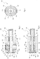
- tensioning system 100 has a base body 110 which carries two clamping bodies 120, which by means of a drive means, which is configured in the preferred embodiment as a differential threaded spindle 122, diametrically opposite directions between a release position, not shown, and in Fig. 2 shown clamping position are adjustable.
- a drive means which is configured in the preferred embodiment as a differential threaded spindle 122, diametrically opposite directions between a release position, not shown, and in Fig. 2 shown clamping position are adjustable.
- an ejector 130 combined with a tubular element 140 is arranged in the main body 110.
- the main body 110 is formed from a rotational body. He wears the outer circumference two integrally molded driver body 111, 112, which are arranged diametrically opposite one another.
- the driver bodies 111, 112 serve for positive locking
- Anchoring of the main body 110 in the in Fig. 1 Part 3 shown in the base body 110 is a along a longitudinal center axis 113 extending central through hole 114 is formed.
- the central through-hole 114 can be produced by drilling and turning. In a first step, a central bore will be made first, which is then reworked in a second step by internal rotation in such a way that two diametrically opposite radial projections 118 are formed, which serve to anchor the ejector 130, which will be explained later.
- the central through-hole 130 merges into a threaded bore 115 on the side facing the driver bodies 111, 112.
- the threaded bore 115 is adapted to a first threaded portion 151 of a formed as a differential threaded bolt 150 connector which by a recess 152 from the first threaded portion 151 separately carries a second threaded portion 153, the thread is formed in the same direction to the thread of the first threaded portion 151, but with a larger pitch.
- the second threaded portion 153 is screwed into a corresponding threaded hole on the side of the part 3 to connect the clamping system 100 to the part 3.
- the ejector 130 is arranged, as shown in FIG Fig. 2, 3rd is shown. The ejector 130 will be explained in detail later.
- a middle section in the axial direction of the base body 110 is provided with two diametrically opposed recesses 116 for positive reception of the two clamping bodies 120.
- the arrangement is made in such a way that the two clamping bodies 120 are guided in their exact fit over their end faces by the side surfaces of the recesses 116 and are held diametrically in opposite directions movably in the housing body 110.
- the clamping bodies 120 are in particular formed by bodies of lenticular shape in cross-section.
- the recesses 116 in the housing body 110 are formed so deep in the radial direction that the clamping body 120 in the recesses 116 are completely retracted.
- the curvature of the outer surface of the two clamping bodies 120 essentially corresponds to the curvature of the cylindrical outer surface of the main body 110.
- the inner surfaces of the two clamping bodies 120 are designed analogously to the base surfaces of the two recesses 116 as plane surfaces.
- the recesses 116 are above it Be formed so deep in the radial direction that they expose central through hole 114 so far that the arranged in the recesses 116 clamping body 120 engage in the release position not shown in the central through hole 114 and the ejector 130 in FIGS. 2 and 3 to the left, ie in the ejection direction, displace.
- the clamping bodies 120 are each provided with radial threaded bores 122 into which the differential threaded spindle 122 is screwed.
- the differential threaded spindle 122 is arranged in a formed in the base body 110 transverse bore 117, which as in Fig. 4 can be seen well, the central through-hole 114 intersects.
- the differential threaded spindle 122 can be driven by means of a radially insertable from the outside key in the manner that Diffferentialgewindespindel 122, the two clamping bodies 120 depending on the direction of rotation of the key in either diametrically outwardly in the in Fig. 2 shown clamping position or diametrically inwardly moved to the release position.
- the two recesses 116 extend radially inward so far or are formed so deep that the central through hole 113 is substantially radially accessible over the entire axial length of the two recesses 120 via this.
- the base surfaces of the two recesses 120 are therefore each formed by two with respect to the longitudinal central axis 113 laterally arranged partial surfaces, of which the one in Fig. 4 easy to recognize.
- the two clamping bodies 120 Upon actuation of the two clamping bodies 120 in the direction of the release position, the two clamping bodies 120 therefore penetrate into the central through-bore 114 and run onto the ejector 130 arranged in the central through-bore 114.
- the two clamping bodies 120 each have a wedge surface 125 on their end faces facing the ejector 130, which is supported on actuation of the two clamping bodies 120 in the direction of the release position on a peripheral wedge flank 131 provided on the ejector 130.
- the two clamping bodies 120 therefore, when moved radially inward, with the peripheral wedge flank 131 on the ejector 130 to the component of a wedge gear.
- the ejector 130 is formed from a cylindrical sleeve body arranged in a precise fit in the central through-bore 114.
- the aforementioned circumferential wedge edge 131 is provided on the two clamping bodies 120 facing the end face of the ejector 130, as in Fig. 2, 3rd and 7 you can see.
- the sleeve body is a rotationally symmetrical elongated hollow body, for example a rotating part, with an at least sectionally rotationally symmetrical, preferably cylindrical outer peripheral surface 133, which ensures a tilt-free guidance of the ejector 130 in the central through-hole 130.
- the ejector 130 is positively in the central through-bore 114 in the base body 110, but anchored with an appropriate for the desired ejection stroke axial play.
- the anchoring is achieved in particular via a kind of bayonet lock.
- the ejector according to 6 and 7 on its lying in pressing end face on an axial extension 133, which is formed from a obtained by ablation of two, in an axial plan view of circular segment-shaped portions web portion 134.
- two diametrically opposed grooves 135 are formed, which provided with in the central through hole 114 radial projections 118 which in 3 and 4 can be seen, are engageable.
- Fig. 3 shows that the axial extension 133 is incorporated in the sleeve body.
- the cylindrical envelope surface of the axial extension 133 is therefore aligned with the cylindrical envelope surface of that portion with the cylindrical outer peripheral surface 133 of the ejector 130.
- the width of the grooves 135 measured in the direction of the longitudinal central axis 113 of the main body 110 is just so large that the radial projections 118 projecting from the inner peripheral surface of the central through-bore 113 are received in the grooves 135 with an axial play corresponding to the desired ejection stroke.
- the ejector 130 is in the release position the two clamping bodies 122 are pressed in the ejection direction against the radial projections 118.
- the ejector 130 is further extended in a flange-like manner radially outward at its ejection-direction end.
- the flange 136 is designed so that it completely immersed in an actuation of the two clamping bodies 120 in the direction of the clamping position in a formed in the base body 110 frontal receiving opening 119 and 120 upon actuation of the two clamping bodies in the release position to the desired ejection stroke from the front Receiving opening 119 extends.
- the ejector 130 further has at its lying in pressing end a central hexagonal recess 132, the use of a corresponding assembly tool, for. B. Allen key, for anchoring the sleeve body 132 in the base 110 allowed.
- FIGS. 5 and 6 show that the ejector 130 is combined with a coolant / lubricant supply pipe 140 concentrically penetrating the central through-bore 114.
- the coolant / lubricant supply pipe 140 is integrally formed with the ejector 130 in the illustrated embodiment. Alternatively, it may also be arranged in the central bore of the ejector 130 formed by the sleeve body with a press fit, whereby it is entrained by the ejector 130 in the axial direction and in the rotational direction about the longitudinal center axis 113.
- the coolant / lubricant supply pipe 140 is snugly received in a central bore of the above-mentioned differential threaded bolt 150.
- the ejector 130 also has on its cylindrical outer peripheral surface 133 a circumferential annular groove 137 in which a sealing ring 160 is received.
- FIGS. 2 and 3 show the clamping system in a preassembled state, which can be achieved as follows: First, in the transverse bore 117, the differential threaded spindle 122 is used on the previously one of the two clamping bodies 120 has been placed. Subsequently, the other of the two clamping bodies 120 on put on the opposite side of the differential screw 122 and screwed by turning the differential screw 122 on this. By further rotation, the differential threaded spindle 122 can be screwed synchronously far into both clamping bodies 122 until the two clamping bodies 122 are held securely on the base body 110. In this state, then the differential threaded bolt 150 can be screwed into the main body 110.
- the ejector 130 combined with the tube element 140 can be inserted into the central through-bore 114 and brought into a rotational position in which the axial extension 133 can pass between the two radial projections 118.
- the tubular element 140 dips into the differential threaded bolt 150 screwed into the main body 110 and the flange 136 into the end-side receiving opening 119 formed in the main body 110.
- the ejector 130 can be rotated with the tube member 140 by about 90 ° to bring the radial projections 118 into engagement with the two grooves 135 on the axial extension 133.
- the two clamping bodies 120 can be brought by further screwing the differential threaded spindle 122 in the release position, whereby the clamping system according to the invention for mounting in the receiving portion 4 of in Fig. 1 Part 2 is ready.
Landscapes
- Engineering & Computer Science (AREA)
- Mechanical Engineering (AREA)
- General Engineering & Computer Science (AREA)
- Clamps And Clips (AREA)
- Auxiliary Devices For Machine Tools (AREA)
- Gripping On Spindles (AREA)
Claims (12)
- Système de serrage pour la liaison détachable de deux parties de préférence symétriques en rotation (1, 3), dont une partie (1) présente un arbre creux (2) de préférence cylindrique ou conique et l'autre partie (3) présente une section de réception (4) pour la réception en ajustement précis de l'arbre creux (2) avec :un corps de base (110) à agencer concentriquement dans la section de réception (4) de l'autre partie (3) qui s'étend dans l'état assemblé l'une avec l'autre des deux parties (1, 3) dans l'arbre creux (2) d'une partie (1) et porte deux corps de serrage (120, 120) qui sont actionnables en sens diamétralement inverse entre une position de détachement et une position de serrage, etun éjecteur (130) maintenu de manière réglable axialement d'une course d'éjection définie dans un perçage débouchant (114) central dans le corps de base (110),dans lequel les deux corps de serrage (120, 120) sollicitent dans la position de serrage l'une partie (1) avec une force de pressage agissant dans un sens de pressage vers l'autre partie (3) et sollicitent dans la position de détachement l'une partie (1) par le biais de l'éjecteur (130) avec une force d'éjection agissant dans un sens d'éjection loin de l'autre partie (3), etdans lequel l'éjecteur (130) est formé à partir d'un corps de rotation qui présente un flanc cunéiforme (131) tournant dirigé dans le sens de pressage, sur lequel les deux corps de serrage (120) montent lors d'un actionnement en direction de la position de détachement, caractérisé en ce quele corps de rotation formant l'éjecteur (130) est ancré de manière détachable directement par complémentarité de formes avec un jeu axial correspondant à la course d'éjection définie dans un perçage débouchant (114) central réalisé dans le corps de base (110).
- Système de serrage selon la revendication 1, caractérisé en ce que l'éjecteur (130) est formé à partir d'un corps de douille.
- Système de serrage selon la revendication 1 ou 2, caractérisé en ce que l'éjecteur (130) est ancré comme une fermeture à baïonnette dans le corps de base (110).
- Système de serrage selon la revendication 3, caractérisé en ce que
l'éjecteur (130) présente dans le sens de pressage un prolongement axial (133) qui est formé à partir d'une section de nervure (134) obtenue par enlèvement de deux sections du corps de rotation en forme de segment de cercle dans une vue en élévation axiale, et
la section de nervure (134) présente deux rainures (135) en regard diamétralement qui peuvent être amenées en engagement avec des saillies radiales (118) agencées en regard diamétralement, prévues dans le perçage débouchant central (114). - Système de serrage selon la revendication 4, caractérisé en ce que les rainures (135) sont configurées sur la section de nervure (134) dans le sens axial avec une dimension précisément si grande que les saillies radiales (118) dans le perçage débouchant (113) central dans les rainures (135) sont reçues avec un jeu axial correspondant à la course d'éjection définie.
- Système de serrage selon l'une des revendications précédentes, caractérisé en ce que
les deux corps de serrage (120) sont reçus par complémentarité de formes dans deux évidements (116) en regard diamétralement dans le corps de base (110) et
les deux évidements (116) s'étendent radialement vers l'intérieur jusqu'à ce qu'ils dégagent le perçage débouchant central (114). - Système de serrage selon l'une des revendications précédentes, caractérisé en ce que l'éjecteur (130) présente une bride tournante (136) sur son extrémité se trouvant dans le sens d'éjection.
- Système de serrage selon la revendication 7, caractérisé en ce que la bride (136) est configurée de sorte qu'elle s'enfonce lors d'un actionnement des deux corps de serrage (120) en direction de la position de serrage dans une ouverture de réception (119) côté avant réalisée dans le corps de base (130) et sort lors d'un actionnement des deux corps de serrage (120) en direction de la position de détachement, de la course d'éjection définie, hors de l'ouverture de réception côté avant (119).
- Système de serrage selon l'une des revendications précédentes, caractérisé par un tube d'amenée de réfrigérant et de lubrifiant combiné (140) à l'éjecteur (130).
- Système de serrage selon la revendication 9, caractérisé en ce que le tube d'amenée de réfrigérant et de lubrifiant (140) est réalisé d'un seul tenant avec l'éjecteur (130).
- Système de serrage selon la revendication 9, caractérisé en ce que le tube d'amenée de réfrigérant et de lubrifiant (140) est relié de manière manipulable d'un seul tenant à l'éjecteur (130).
- Système de serrage selon l'une des revendications précédentes, caractérisé en ce que l'éjecteur (130) présente, sur son côté avant dirigé dans le sens de pressage, un évidement de réception d'outil (132) pour la réception d'un outil correspondant.
Applications Claiming Priority (2)
| Application Number | Priority Date | Filing Date | Title |
|---|---|---|---|
| DE102011005052A DE102011005052A1 (de) | 2011-03-03 | 2011-03-03 | Spannsystem zur lösbaren Verbindung zweier vorzugsweise rotationssymetrischer Teile |
| PCT/EP2012/053742 WO2012117118A1 (fr) | 2011-03-03 | 2012-03-05 | Système de serrage permettant de relier de manière libérable deux éléments de préférence à symétrie de révolution |
Publications (2)
| Publication Number | Publication Date |
|---|---|
| EP2555894A1 EP2555894A1 (fr) | 2013-02-13 |
| EP2555894B1 true EP2555894B1 (fr) | 2017-06-21 |
Family
ID=45808926
Family Applications (1)
| Application Number | Title | Priority Date | Filing Date |
|---|---|---|---|
| EP12707574.5A Active EP2555894B1 (fr) | 2011-03-03 | 2012-03-05 | Dispositif de serrage pour la fixation détachable de deux pièces de préférence à symétrie de rotation |
Country Status (6)
| Country | Link |
|---|---|
| US (1) | US9157481B2 (fr) |
| EP (1) | EP2555894B1 (fr) |
| JP (1) | JP5980819B2 (fr) |
| KR (1) | KR20140013011A (fr) |
| DE (1) | DE102011005052A1 (fr) |
| WO (1) | WO2012117118A1 (fr) |
Families Citing this family (5)
| Publication number | Priority date | Publication date | Assignee | Title |
|---|---|---|---|---|
| DE102011005052A1 (de) * | 2011-03-03 | 2012-09-06 | Gühring Ohg | Spannsystem zur lösbaren Verbindung zweier vorzugsweise rotationssymetrischer Teile |
| DE102014114779B3 (de) * | 2014-10-13 | 2016-01-28 | Gühring KG | Spannpatrone zur Ankopplung eines Werkzeugadapters an eine Motorspindel einer Werkzeugmaschine |
| CN107314043B (zh) * | 2017-08-31 | 2023-05-23 | 重庆巴欧机电有限公司 | 一种同向传动机构 |
| DE102017223291A1 (de) * | 2017-12-19 | 2019-06-19 | Continental Teves Ag & Co. Ohg | Verdrehsichere Hohlschaftverbindung |
| CN115996674B (zh) * | 2020-08-04 | 2025-11-11 | 奥林巴斯株式会社 | 超声波处置器具及超声波处置器具的制造方法 |
Family Cites Families (14)
| Publication number | Priority date | Publication date | Assignee | Title |
|---|---|---|---|---|
| US2102576A (en) * | 1936-05-06 | 1937-12-14 | Independent Pneumatic Tool Co | Rock drill sludge ejector |
| GB1018919A (en) * | 1963-11-02 | 1966-02-02 | Impex Essen Vertrieb | Improvements in or relating to tool holders, particularly for use with electric or compressed air hammers |
| DE2439329C3 (de) * | 1974-08-16 | 1982-02-25 | Moeller & Neumann Gmbh, 6670 St Ingbert | Rollenbefestigung für Rollenrichtmaschinen |
| JPS62157748A (ja) * | 1985-12-30 | 1987-07-13 | Kyoritsu Seiki Kk | 工作機械に於ける工具交換継手 |
| JPH09136204A (ja) * | 1995-11-13 | 1997-05-27 | Toshiba Tungaloy Co Ltd | 工具着脱装置 |
| FR2754201B1 (fr) * | 1996-10-04 | 1998-12-11 | E P B Emile Pfalzgraf | Dispositif de serrage d'attachements a cone creux |
| EP1056563B1 (fr) * | 1998-01-23 | 2002-10-09 | KOMET Präzisionswerkzeuge Robert Breuning GmbH | Dispositif pour raccorder une tete d'outil a une tige de serrage |
| DE19920748A1 (de) * | 1999-05-05 | 2000-11-09 | Guehring Joerg | Spannsystem für hohe Drehzahlen |
| DE102004009217A1 (de) * | 2004-02-12 | 2005-09-01 | Gühring, Jörg, Dr. | Spannelement für Werkzeugspanner |
| DE102004021082A1 (de) * | 2004-04-29 | 2005-11-17 | Bilz Werkzeugfabrik Gmbh & Co. Kg | Schnellwechseleinsatz für Werkzeuge, insbesondere für Gewindebohrer |
| DE102006055422B4 (de) | 2006-08-30 | 2016-06-30 | Gühring KG | Spannsystem zur lösbaren Verbindung zweier Teile |
| DE102007024552B4 (de) | 2007-05-24 | 2016-02-11 | Gühring KG | Spannvorrichtung |
| DE102010013156A1 (de) * | 2010-03-27 | 2011-09-29 | Volkswagen Ag | Spanneinrichtung |
| DE102011005052A1 (de) * | 2011-03-03 | 2012-09-06 | Gühring Ohg | Spannsystem zur lösbaren Verbindung zweier vorzugsweise rotationssymetrischer Teile |
-
2011
- 2011-03-03 DE DE102011005052A patent/DE102011005052A1/de not_active Withdrawn
-
2012
- 2012-03-05 KR KR1020137025999A patent/KR20140013011A/ko not_active Ceased
- 2012-03-05 WO PCT/EP2012/053742 patent/WO2012117118A1/fr not_active Ceased
- 2012-03-05 JP JP2013555899A patent/JP5980819B2/ja not_active Expired - Fee Related
- 2012-03-05 EP EP12707574.5A patent/EP2555894B1/fr active Active
-
2013
- 2013-08-19 US US13/969,960 patent/US9157481B2/en not_active Expired - Fee Related
Non-Patent Citations (1)
| Title |
|---|
| None * |
Also Published As
| Publication number | Publication date |
|---|---|
| DE102011005052A1 (de) | 2012-09-06 |
| EP2555894A1 (fr) | 2013-02-13 |
| JP5980819B2 (ja) | 2016-08-31 |
| JP2014511284A (ja) | 2014-05-15 |
| KR20140013011A (ko) | 2014-02-04 |
| US9157481B2 (en) | 2015-10-13 |
| DE102011005052A8 (de) | 2013-01-17 |
| WO2012117118A1 (fr) | 2012-09-07 |
| US20140105681A1 (en) | 2014-04-17 |
Similar Documents
| Publication | Publication Date | Title |
|---|---|---|
| DE102012212146B4 (de) | Kupplungsstelle für ein modulares Rotationswerkzeug sowie Werkzeugkopf und Träger für ein solches modulares Rotationswerkzeug | |
| DE102010025653A1 (de) | Rotations-Schneidwerkzeug | |
| EP2542368B1 (fr) | Dispositif pour l'assemblage de deux composants | |
| DE102013217753B3 (de) | Kupplungselement, Kupplungsanordnung sowie Verfahren zur Herstellung eines Kupplungselements | |
| DE102007022186A1 (de) | Adapter zum Betreiben einer Lochsäge an einer Antriebsmaschine | |
| EP2913561B1 (fr) | Système d'engrenage planétaire motorisé et procédé permettant de relier un moteur à un engrenage planétaire pour fabriquer un agencement moteur-engrenage planétaire | |
| EP2555894B1 (fr) | Dispositif de serrage pour la fixation détachable de deux pièces de préférence à symétrie de rotation | |
| DE3433878A1 (de) | Axial-spannverbindung | |
| EP2832478B1 (fr) | Système de connexion et douille intermédiaire et kit doté d'une douille intermédiaire et d'une vis d'arrêt destinée à être utilisée dans un tel système de connexion | |
| EP2681000A1 (fr) | Filière | |
| WO2013033849A1 (fr) | Dispositif de poussée pour un fil de soudure | |
| DE102012222627B4 (de) | Rohrförmige Vorrichtung zur Verbindung mit einer Welle | |
| EP2736665A1 (fr) | Dispositif de serrage pour machine d'équilibrage | |
| WO2007031285A1 (fr) | Dispositif pour realiser un couplage amovible de deux pieces | |
| DE3427125C2 (de) | Teilbares Werkzeug für die spanabhebende Bearbeitung | |
| EP3016770B2 (fr) | Système de tête interchangeable pour l'usinage de métaux | |
| EP3747578A1 (fr) | Dispositif de serrage permettant de serrer un objet | |
| EP2292358A2 (fr) | Dispositif doté d'une réception pour un outil de coupe | |
| EP1988311B1 (fr) | Palier et actionneur linéaire équipé d'un tel palier | |
| DE102014114445A1 (de) | Spannfutter | |
| EP4155015A1 (fr) | Dispositif de serrage pour un outil ou une pièce à usiner doté d'une pince de serrage et d'un élément de serrage pour un dispositif de serrage et procédé de serrage d'un dispositif de serrage ou de serrage | |
| WO1991008072A2 (fr) | Systeme de serrage permettant de relier des pieces de façon a eviter leur rotation ou leur deplacement cyclique | |
| DE102015112049B3 (de) | Spannzangensystem mit Positionierung | |
| CH707765A2 (de) | Bearbeitbarer Rohling für die Herstellung eines rotierenden oder stehenden Werkzeugs. | |
| DE3326665C2 (de) | Teilbares Werkzeug für die spanabhebende Bearbeitung |
Legal Events
| Date | Code | Title | Description |
|---|---|---|---|
| PUAI | Public reference made under article 153(3) epc to a published international application that has entered the european phase |
Free format text: ORIGINAL CODE: 0009012 |
|
| 17P | Request for examination filed |
Effective date: 20121106 |
|
| AK | Designated contracting states |
Kind code of ref document: A1 Designated state(s): AL AT BE BG CH CY CZ DE DK EE ES FI FR GB GR HR HU IE IS IT LI LT LU LV MC MK MT NL NO PL PT RO RS SE SI SK SM TR |
|
| DAX | Request for extension of the european patent (deleted) | ||
| 17Q | First examination report despatched |
Effective date: 20160408 |
|
| RAP1 | Party data changed (applicant data changed or rights of an application transferred) |
Owner name: GUEHRING KG |
|
| GRAP | Despatch of communication of intention to grant a patent |
Free format text: ORIGINAL CODE: EPIDOSNIGR1 |
|
| INTG | Intention to grant announced |
Effective date: 20161206 |
|
| GRAS | Grant fee paid |
Free format text: ORIGINAL CODE: EPIDOSNIGR3 |
|
| GRAJ | Information related to disapproval of communication of intention to grant by the applicant or resumption of examination proceedings by the epo deleted |
Free format text: ORIGINAL CODE: EPIDOSDIGR1 |
|
| GRAL | Information related to payment of fee for publishing/printing deleted |
Free format text: ORIGINAL CODE: EPIDOSDIGR3 |
|
| GRAR | Information related to intention to grant a patent recorded |
Free format text: ORIGINAL CODE: EPIDOSNIGR71 |
|
| GRAA | (expected) grant |
Free format text: ORIGINAL CODE: 0009210 |
|
| INTC | Intention to grant announced (deleted) | ||
| AK | Designated contracting states |
Kind code of ref document: B1 Designated state(s): AL AT BE BG CH CY CZ DE DK EE ES FI FR GB GR HR HU IE IS IT LI LT LU LV MC MK MT NL NO PL PT RO RS SE SI SK SM TR |
|
| INTG | Intention to grant announced |
Effective date: 20170512 |
|
| REG | Reference to a national code |
Ref country code: GB Ref legal event code: FG4D Free format text: NOT ENGLISH |
|
| REG | Reference to a national code |
Ref country code: CH Ref legal event code: EP |
|
| REG | Reference to a national code |
Ref country code: IE Ref legal event code: FG4D Free format text: LANGUAGE OF EP DOCUMENT: GERMAN |
|
| REG | Reference to a national code |
Ref country code: AT Ref legal event code: REF Ref document number: 902465 Country of ref document: AT Kind code of ref document: T Effective date: 20170715 |
|
| REG | Reference to a national code |
Ref country code: DE Ref legal event code: R096 Ref document number: 502012010592 Country of ref document: DE |
|
| REG | Reference to a national code |
Ref country code: NL Ref legal event code: MP Effective date: 20170621 |
|
| PG25 | Lapsed in a contracting state [announced via postgrant information from national office to epo] |
Ref country code: HR Free format text: LAPSE BECAUSE OF FAILURE TO SUBMIT A TRANSLATION OF THE DESCRIPTION OR TO PAY THE FEE WITHIN THE PRESCRIBED TIME-LIMIT Effective date: 20170621 Ref country code: FI Free format text: LAPSE BECAUSE OF FAILURE TO SUBMIT A TRANSLATION OF THE DESCRIPTION OR TO PAY THE FEE WITHIN THE PRESCRIBED TIME-LIMIT Effective date: 20170621 Ref country code: LT Free format text: LAPSE BECAUSE OF FAILURE TO SUBMIT A TRANSLATION OF THE DESCRIPTION OR TO PAY THE FEE WITHIN THE PRESCRIBED TIME-LIMIT Effective date: 20170621 Ref country code: GR Free format text: LAPSE BECAUSE OF FAILURE TO SUBMIT A TRANSLATION OF THE DESCRIPTION OR TO PAY THE FEE WITHIN THE PRESCRIBED TIME-LIMIT Effective date: 20170922 Ref country code: NO Free format text: LAPSE BECAUSE OF FAILURE TO SUBMIT A TRANSLATION OF THE DESCRIPTION OR TO PAY THE FEE WITHIN THE PRESCRIBED TIME-LIMIT Effective date: 20170921 |
|
| REG | Reference to a national code |
Ref country code: LT Ref legal event code: MG4D |
|
| PG25 | Lapsed in a contracting state [announced via postgrant information from national office to epo] |
Ref country code: SE Free format text: LAPSE BECAUSE OF FAILURE TO SUBMIT A TRANSLATION OF THE DESCRIPTION OR TO PAY THE FEE WITHIN THE PRESCRIBED TIME-LIMIT Effective date: 20170621 Ref country code: RS Free format text: LAPSE BECAUSE OF FAILURE TO SUBMIT A TRANSLATION OF THE DESCRIPTION OR TO PAY THE FEE WITHIN THE PRESCRIBED TIME-LIMIT Effective date: 20170621 Ref country code: NL Free format text: LAPSE BECAUSE OF FAILURE TO SUBMIT A TRANSLATION OF THE DESCRIPTION OR TO PAY THE FEE WITHIN THE PRESCRIBED TIME-LIMIT Effective date: 20170621 Ref country code: BG Free format text: LAPSE BECAUSE OF FAILURE TO SUBMIT A TRANSLATION OF THE DESCRIPTION OR TO PAY THE FEE WITHIN THE PRESCRIBED TIME-LIMIT Effective date: 20170921 Ref country code: LV Free format text: LAPSE BECAUSE OF FAILURE TO SUBMIT A TRANSLATION OF THE DESCRIPTION OR TO PAY THE FEE WITHIN THE PRESCRIBED TIME-LIMIT Effective date: 20170621 |
|
| PG25 | Lapsed in a contracting state [announced via postgrant information from national office to epo] |
Ref country code: CZ Free format text: LAPSE BECAUSE OF FAILURE TO SUBMIT A TRANSLATION OF THE DESCRIPTION OR TO PAY THE FEE WITHIN THE PRESCRIBED TIME-LIMIT Effective date: 20170621 Ref country code: RO Free format text: LAPSE BECAUSE OF FAILURE TO SUBMIT A TRANSLATION OF THE DESCRIPTION OR TO PAY THE FEE WITHIN THE PRESCRIBED TIME-LIMIT Effective date: 20170621 Ref country code: SK Free format text: LAPSE BECAUSE OF FAILURE TO SUBMIT A TRANSLATION OF THE DESCRIPTION OR TO PAY THE FEE WITHIN THE PRESCRIBED TIME-LIMIT Effective date: 20170621 Ref country code: EE Free format text: LAPSE BECAUSE OF FAILURE TO SUBMIT A TRANSLATION OF THE DESCRIPTION OR TO PAY THE FEE WITHIN THE PRESCRIBED TIME-LIMIT Effective date: 20170621 |
|
| PG25 | Lapsed in a contracting state [announced via postgrant information from national office to epo] |
Ref country code: IT Free format text: LAPSE BECAUSE OF FAILURE TO SUBMIT A TRANSLATION OF THE DESCRIPTION OR TO PAY THE FEE WITHIN THE PRESCRIBED TIME-LIMIT Effective date: 20170621 Ref country code: ES Free format text: LAPSE BECAUSE OF FAILURE TO SUBMIT A TRANSLATION OF THE DESCRIPTION OR TO PAY THE FEE WITHIN THE PRESCRIBED TIME-LIMIT Effective date: 20170621 Ref country code: PL Free format text: LAPSE BECAUSE OF FAILURE TO SUBMIT A TRANSLATION OF THE DESCRIPTION OR TO PAY THE FEE WITHIN THE PRESCRIBED TIME-LIMIT Effective date: 20170621 Ref country code: IS Free format text: LAPSE BECAUSE OF FAILURE TO SUBMIT A TRANSLATION OF THE DESCRIPTION OR TO PAY THE FEE WITHIN THE PRESCRIBED TIME-LIMIT Effective date: 20171021 Ref country code: SM Free format text: LAPSE BECAUSE OF FAILURE TO SUBMIT A TRANSLATION OF THE DESCRIPTION OR TO PAY THE FEE WITHIN THE PRESCRIBED TIME-LIMIT Effective date: 20170621 |
|
| REG | Reference to a national code |
Ref country code: DE Ref legal event code: R097 Ref document number: 502012010592 Country of ref document: DE |
|
| PLBE | No opposition filed within time limit |
Free format text: ORIGINAL CODE: 0009261 |
|
| STAA | Information on the status of an ep patent application or granted ep patent |
Free format text: STATUS: NO OPPOSITION FILED WITHIN TIME LIMIT |
|
| PG25 | Lapsed in a contracting state [announced via postgrant information from national office to epo] |
Ref country code: DK Free format text: LAPSE BECAUSE OF FAILURE TO SUBMIT A TRANSLATION OF THE DESCRIPTION OR TO PAY THE FEE WITHIN THE PRESCRIBED TIME-LIMIT Effective date: 20170621 |
|
| 26N | No opposition filed |
Effective date: 20180322 |
|
| PG25 | Lapsed in a contracting state [announced via postgrant information from national office to epo] |
Ref country code: SI Free format text: LAPSE BECAUSE OF FAILURE TO SUBMIT A TRANSLATION OF THE DESCRIPTION OR TO PAY THE FEE WITHIN THE PRESCRIBED TIME-LIMIT Effective date: 20170621 |
|
| PG25 | Lapsed in a contracting state [announced via postgrant information from national office to epo] |
Ref country code: MT Free format text: LAPSE BECAUSE OF FAILURE TO SUBMIT A TRANSLATION OF THE DESCRIPTION OR TO PAY THE FEE WITHIN THE PRESCRIBED TIME-LIMIT Effective date: 20170621 |
|
| REG | Reference to a national code |
Ref country code: CH Ref legal event code: PL |
|
| GBPC | Gb: european patent ceased through non-payment of renewal fee |
Effective date: 20180305 |
|
| PG25 | Lapsed in a contracting state [announced via postgrant information from national office to epo] |
Ref country code: MC Free format text: LAPSE BECAUSE OF FAILURE TO SUBMIT A TRANSLATION OF THE DESCRIPTION OR TO PAY THE FEE WITHIN THE PRESCRIBED TIME-LIMIT Effective date: 20170621 |
|
| REG | Reference to a national code |
Ref country code: BE Ref legal event code: MM Effective date: 20180331 |
|
| REG | Reference to a national code |
Ref country code: IE Ref legal event code: MM4A |
|
| PG25 | Lapsed in a contracting state [announced via postgrant information from national office to epo] |
Ref country code: LU Free format text: LAPSE BECAUSE OF NON-PAYMENT OF DUE FEES Effective date: 20180305 |
|
| PG25 | Lapsed in a contracting state [announced via postgrant information from national office to epo] |
Ref country code: IE Free format text: LAPSE BECAUSE OF NON-PAYMENT OF DUE FEES Effective date: 20180305 |
|
| PG25 | Lapsed in a contracting state [announced via postgrant information from national office to epo] |
Ref country code: BE Free format text: LAPSE BECAUSE OF NON-PAYMENT OF DUE FEES Effective date: 20180331 Ref country code: GB Free format text: LAPSE BECAUSE OF NON-PAYMENT OF DUE FEES Effective date: 20180305 Ref country code: LI Free format text: LAPSE BECAUSE OF NON-PAYMENT OF DUE FEES Effective date: 20180331 Ref country code: CH Free format text: LAPSE BECAUSE OF NON-PAYMENT OF DUE FEES Effective date: 20180331 |
|
| PG25 | Lapsed in a contracting state [announced via postgrant information from national office to epo] |
Ref country code: FR Free format text: LAPSE BECAUSE OF NON-PAYMENT OF DUE FEES Effective date: 20180331 |
|
| REG | Reference to a national code |
Ref country code: AT Ref legal event code: MM01 Ref document number: 902465 Country of ref document: AT Kind code of ref document: T Effective date: 20180305 |
|
| PG25 | Lapsed in a contracting state [announced via postgrant information from national office to epo] |
Ref country code: AT Free format text: LAPSE BECAUSE OF NON-PAYMENT OF DUE FEES Effective date: 20180305 |
|
| PG25 | Lapsed in a contracting state [announced via postgrant information from national office to epo] |
Ref country code: TR Free format text: LAPSE BECAUSE OF FAILURE TO SUBMIT A TRANSLATION OF THE DESCRIPTION OR TO PAY THE FEE WITHIN THE PRESCRIBED TIME-LIMIT Effective date: 20170621 |
|
| PG25 | Lapsed in a contracting state [announced via postgrant information from national office to epo] |
Ref country code: PT Free format text: LAPSE BECAUSE OF FAILURE TO SUBMIT A TRANSLATION OF THE DESCRIPTION OR TO PAY THE FEE WITHIN THE PRESCRIBED TIME-LIMIT Effective date: 20170621 Ref country code: HU Free format text: LAPSE BECAUSE OF FAILURE TO SUBMIT A TRANSLATION OF THE DESCRIPTION OR TO PAY THE FEE WITHIN THE PRESCRIBED TIME-LIMIT; INVALID AB INITIO Effective date: 20120305 |
|
| PG25 | Lapsed in a contracting state [announced via postgrant information from national office to epo] |
Ref country code: MK Free format text: LAPSE BECAUSE OF NON-PAYMENT OF DUE FEES Effective date: 20170621 Ref country code: CY Free format text: LAPSE BECAUSE OF FAILURE TO SUBMIT A TRANSLATION OF THE DESCRIPTION OR TO PAY THE FEE WITHIN THE PRESCRIBED TIME-LIMIT Effective date: 20170621 |
|
| PG25 | Lapsed in a contracting state [announced via postgrant information from national office to epo] |
Ref country code: AL Free format text: LAPSE BECAUSE OF FAILURE TO SUBMIT A TRANSLATION OF THE DESCRIPTION OR TO PAY THE FEE WITHIN THE PRESCRIBED TIME-LIMIT Effective date: 20170621 |
|
| PGFP | Annual fee paid to national office [announced via postgrant information from national office to epo] |
Ref country code: DE Payment date: 20260331 Year of fee payment: 15 |