EP2555962B1 - Modularer karosserieaufbau eines kraftfahrzeugs - Google Patents
Modularer karosserieaufbau eines kraftfahrzeugs Download PDFInfo
- Publication number
- EP2555962B1 EP2555962B1 EP11716818.7A EP11716818A EP2555962B1 EP 2555962 B1 EP2555962 B1 EP 2555962B1 EP 11716818 A EP11716818 A EP 11716818A EP 2555962 B1 EP2555962 B1 EP 2555962B1
- Authority
- EP
- European Patent Office
- Prior art keywords
- body structure
- suspension strut
- strut
- strut mounting
- dome
- Prior art date
- Legal status (The legal status is an assumption and is not a legal conclusion. Google has not performed a legal analysis and makes no representation as to the accuracy of the status listed.)
- Active
Links
Images

Classifications
-
- B—PERFORMING OPERATIONS; TRANSPORTING
- B62—LAND VEHICLES FOR TRAVELLING OTHERWISE THAN ON RAILS
- B62D—MOTOR VEHICLES; TRAILERS
- B62D25/00—Superstructure or monocoque structure sub-units; Parts or details thereof not otherwise provided for
- B62D25/08—Front or rear portions
- B62D25/088—Details of structures as upper supports for springs or dampers
-
- B—PERFORMING OPERATIONS; TRANSPORTING
- B62—LAND VEHICLES FOR TRAVELLING OTHERWISE THAN ON RAILS
- B62D—MOTOR VEHICLES; TRAILERS
- B62D63/00—Motor vehicles or trailers not otherwise provided for
- B62D63/02—Motor vehicles
- B62D63/025—Modular vehicles
Definitions
- the invention relates to a modular body structure of a motor vehicle according to the preamble of claim 1.
- spring struts are usually used in particular for suspension of the front wheels, as they bring advantages in terms of function, the required space and weight.
- the struts are each attached and supported at the upper end in a dome of a strut mount.
- the strut mount is part of the body structure and formed together with other adjacent body structure panels.
- the position of the strut tower in the body structure is decisive for the wheel guidance and the suspension properties, so that the formation of the strut mountings takes place in a generally known manner individually for each vehicle type. For a manufacturer of different vehicle types and vehicle variants, this requires a large number of different body components with correspondingly high costs for production, logistics and assembly.
- the object of the invention is to develop a generic body structure of a motor vehicle so that with little effort different strut layers can be realized within wide limits.
- a first strut mounting module with a specific dome formation and with connection elements of a specific connection geometry is available for connection to associated body structure elements.
- at least one other strut mounting module with the same connection geometry but different Dom for a variation of the body structure with respect to the strut position are available.
- the variation of the suspension strut position is thus carried out on the body side by the use of different shock absorber modules, wherein each advantageously a same damper head can be installed in an adapted thereto small receiving opening of the shock absorber module.
- two mirror-inverted embodiments of a first strut receiving module for a left-side and right-side installation in the front of a body are provided.
- two mirror-image versions of a second shock absorber module with different dome formation are provided for the realization of a second suspension strut position, which can be installed alternately depending on the desired vehicle type.
- the differences in the dome formation may lie in the fact that the dome convexity can be varied with its central opening with respect to the respectively same connection geometry both in the vertical position and in the lateral position or an inclination ,
- connection elements of the connection contour of the strut mounting modules can be formed simply by sheet metal regions of the Domanschrägung and / or by downwardly approximately vertically projecting connecting plates.
- the spring strut mount has a relatively small approximately horizontal area for supporting the shock absorber around its relatively small receiving opening, the wall of the strut tower then being in a slope (wall area (5, 17 in FIG Fig. 3 ) for an optimized introduction of forces into the body. This can be prevented or at least significantly reduced unwanted vibrations.
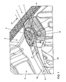
- Fig. 1 is partially a body structure 1 in the left part of a front end 2 of a motor vehicle in the region of a strut mount 3 shown.
- the strut mount 3 is here produced with a first strut receiving module 4 on which a strut tower 5 is formed with a central opening 6 and connecting holes 7.
- a strut 21 is connected, which is formed from a water box base 22 and a water box front part 23.
- This strut tower 5 has in the mounted position of the strut mounting module 4 with respect to the front body structure 2 a certain position which determines the strut position of the vehicle type assigned here.
- a second strut mounting module 8 installed with a modified in terms of its position Federbeindom 9, which for this purpose a correspondingly modified suspension strut layer of another vehicle type is higher and further laterally outside.
- the position of the spring leg 5 of the first strut receiving module 4 with the dashed line 10 is located here.
- Fig. 1 comparatively the higher and more laterally positioned position of the strut tower 9 indicated by the dashed line 11.
- the components modified for the second suspension strut mounting module are dotted - the remaining area is formed by identical parts.
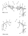
- Fig. 1 is schematically the first strut receiving module 4 with the buckled Federbeindom 5 and the central opening 6 can be seen in the already a strut 12 is inserted with its upper end and bolted to the connection holes 7.
- an upper plenum 13 and a lower plenum 14 are each shown in the connection areas 15, 16 to the strut mounting module 4.
- the upper water panel 13 is connected with a fold surface with a Domanschrägung 17 of the strut tower 5.
- the ratio Width to height preferably to be chosen so that the folded flange of the water box plate 13 is turned off as steep as possible to optionally provide the largest possible Radokgang available.
- the lower water box plate 14 is connected to an edge strip with a vertically downwardly projecting connecting plate 18 of the strut receiving module 4.
- Fig. 4 is a cut accordingly Fig. 3 off along the BB line Fig. 2 (Without strut 12) shown, in which instead of the strut mounting module 4, the modified second strut mounting module 8 is installed, in which case the connection to a longitudinal member 24 is located on the left side.
- the connection geometry in the connection areas 15, 16 to the upper plenum 13 and the lower plenum 14 is unchanged.
- dashed line 10 is here again comparatively the position of the spring leg 5 and in Fig. 3 drawn with the dashed line 11, the position of the strut tower 9. It can be seen that the strut tower 9 on the left side of Fig.
Landscapes
- Engineering & Computer Science (AREA)
- Chemical & Material Sciences (AREA)
- Combustion & Propulsion (AREA)
- Transportation (AREA)
- Mechanical Engineering (AREA)
- Body Structure For Vehicles (AREA)
- Vehicle Body Suspensions (AREA)
- Arrangement Or Mounting Of Propulsion Units For Vehicles (AREA)
Description
- Die Erfindung betrifft einen modularen Karosserieaufbau eines Kraftfahrzeugs nach dem Oberbegriff des Anspruchs 1.
- Bei Kraftfahrzeugen werden insbesondere zur Federung der Vorderräder üblicherweise Federbeine verwendet, da diese hinsichtlich der Funktion, des erforderlichen Bauraums und des Gewichts Vorteile bringen. Dabei werden die Federbeine jeweils am oberen Ende in einem Dom einer Federbeinaufnahme befestigt und abgestützt. Die Federbeinaufnahme ist dabei Bestandteil des Karosserieaufbaus und zusammen mit weiteren angrenzenden Karosseriestrukturblechen ausgebildet.
- Die Lage des Federbeindoms im Karosserieaufbau ist dabei maßgeblich für die Radführung und die Fahrwerkeigenschaften, so dass die Ausbildung der Federbeinaufnahmen in allgemein bekannter Weise individuell für jeden Fahrzeugtyp erfolgt. Dies bedingt bei einem Hersteller unterschiedlicher Fahrzeugtypen und Fahrzeugvarianten eine Vielzahl unterschiedlicher Karosseriebauteile mit entsprechend hohen Kosten für die Herstellung, die Logistik und die Montage.
- Es ist bereits bekannt unterschiedliche Federbeinlagen unter Verwendung gleicher Bauteile zu realisieren (
DE 10 2005 025 611 A1 ). Hier wird vorgeschlagen für unterschiedliche Höhenlagen von Federbeinen in den zugeordneten Federbeindom an Einlegerscheiben unterschiedlicher. Stärken einzusetzen. Damit ist jedoch nur eine unterschiedliche Abstützhöhe eines Federbeins zu erreichen. Ein zusätzlicher konstruktiver Freiraum für eine allgemeine Variation der Federbeinlage ist damit nicht gegeben. - Weiter ist es bekannt (
EP 1 197 360 A2 ) durch Verwendung von Adapterteilen einen Federbeindom im Karosserieaufbau so anzuordnen, dass damit ein relativ großer Abstand zu einer darüber liegenden Frontklappe für einen Fußgängeraufprallschutz erreicht wird. - Weiter ist es bekannt, Fahrzeugvarianten mit modifiziertem Aussehen und/oder modifizierten Funktionen möglichst kostengünstig unter Verwendung möglichst vieler Gleichteile herzustellen:
- Dazu ist es beispielsweise bekannt (
DE 10 2004 035 530 A1 ) bei einem modularen Karosserieaufbau unterschiedliche Fahrgastzellen mit unterschiedlichen Vorderwagen zu kombinieren. Zudem ist es bekannt (DE 103 01 183 A1 ) eine Kotflügelbank mit gestuften Anschlussebenen herzustellen, an denen jeweils gleiche Kotflügel für eine Variation des Fahrzeugaussehens in unterschiedlichen Höhenpositionen angebracht werden können. Für einen ähnlichen Zweck ist es auch bekannt (DE 100 23 193 A1 ) bei sonst gleichen Anschlussteilen unterschiedliche Kotflügelbänke für Typenvariationen zur Verfügung zu stellen. - Zudem ist es bekannt (
EP 0 326 710 A2 ) zur Realisierung von zwei Radspurweiten an Fahrzeugen jeweils Federbeine mit zwei entsprechend in der Einbaulage unterschiedlichen Dämpferkopfausbildungen vorzusehen. Dazu wird an einem aufbauseitigen etwa horizontalen Anschlussblech einer Lageraufnahme eine relativ große Öffnung vorgehalten, in der jeweils entsprechend der gewünschten Radspurweite der Dämpferkopf mit einem Lagerflansch, zu dem ein Dämpfer exzentrisch angeordnet ist, abgestützt und befestigt wird. Die Anpassung an unterschiedliche Radspurweiten wird hier somit über eine Modifikation des Dämpferkopfes erreicht, was nachteilig eine große Öffnung an der Lageraufnahme erfordert. Zudem ist keine optimale Krafteinleitung in die Karosserie über das horizontale mit einer großen Öffnung versehene Anschlussblech zu erreichen. - Aufgabe der Erfindung ist es, einen gattungsgemäßen Karosserieaufbau eines Kraftfahrzeugs so weiterzubilden, dass mit wenig Aufwand unterschiedliche Federbeinlagen in weiten Grenzen realisierbar sind.
- Diese Aufgabe wird dadurch gelöst, dass bei einem wenigstens teilweisen modularen Karosserieaufbau ein erstes Federbeinaufnahme-Modul mit einer bestimmten Domausbildung und mit Anschlusselementen einer bestimmten Anschlussgeometrie für die Verbindung mit zugeordneten Karosseriestrukturelementen zur Verfügung steht. Zudem soll wenigstens ein weiteres Federbeinaufnahme-Modul mit gleicher Anschlussgeometrie jedoch unterschiedlicher Domausbildung für eine Variation des Karosserieaufbaus hinsichtlich der Federbeinlage zur Verfügung stehen.
- Damit kann bei einem sonst gleichen oder weitgehend gleichen Karosserieaufbau eine Variation der Federbeinlage insbesondere für unterschiedliche Fahrzeugvarianten oder Fahrzeugklassen realisiert werden, wobei lediglich die Federbeinaufnahme-Modulteile unterschiedlich gestaltet sind und keine Gleichteile darstellen. Der Karosserieaufbau für unterschiedliche Fahrzeugtypen mit entsprechend unterschiedlichen Federbeinlagen kann damit vergleichsweise kostengünstiger als mit dem bisherigen individuellen Aufbau von Federbeinaufnahmen durchgeführt werden.
- Die Variation der Federbeinlage wird hier somit aufbauseitig durch die Verwendung unterschiedlicher Federbeinaufnahme-Module durchgeführt, wobei vorteilhaft jeweils ein gleicher Dämpferkopf in einer daran angepassten kleinen Aufnahmeöffnung des Federbeinaufnahme-Moduls verbaut werden kann.
- In einer konkreten Ausführungsform werden zwei spiegelbildlich gleiche Ausführungen eines ersten Federbeinaufnahmemoduls für einen linksseitigen und rechtsseitigen Einbau in den Vorderwagen einer Karosserie zur Verfügung gestellt. Zudem werden zur Realisierung einer zweiten Federbeinlage entsprechend zwei spiegelbildliche Ausführungen eines zweiten Federbeinaufnahmemoduls mit unterschiedlicher Domausbildung zur Verfügung gestellt, die je nach gewünschtem Fahrzeugtyp wechselweise verbaut werden können.
- Erfindungsgemäß ist eine große konstruktive Freiheit in der Lagedimensionierung von Federbeinen möglich, da die Unterschiede in der Domausbildung darin liegen können, dass die Domauswölbung mit seiner zentralen Öffnung bezüglich der jeweils gleichen Anschlussgeometrie sowohl in der Höhenlage als auch in der Seitenlage oder einer Schrägstellung variiert werden kann.
- Konkret können die Anschlusselemente der Anschlusskontur der Federbeinaufnahme-Module einfach durch Blechbereiche der Domanschrägung und/oder durch nach unten etwa vertikal abragende Anschlussbleche gebildet sein. Vorteilhaft hat die Federbeinaufnahme um seine relativ kleine Aufnahmeöffnung einen wiederum relativ kleinen etwa horizontalen Bereich zur Abstützung des Federbeins, wobei anschließend an diesen Bereich die Wandung des Federbeindoms in eine Schräge (Wandbereich (5; 17 in
Fig. 3 ) für eine optimierte Einleitung der Kräfte in die Karosserie übergeht. Damit können unerwünschte Schwingungen verhindert oder zumindest wesentlich reduziert werden. - Als Karosseriestrukturelemente für eine Verbindung mit einem Federbeinaufnahmemodul können einfach Blechteile eines angrenzenden Wasserkastens verwendet werden, die gegebenenfalls einerseits mit einer Domanschrägung und andererseits mit einem etwa vertikal nach unten abragenden Anschlussblech des Federbeinaufnahmemoduls verbunden werden.
- Anhand einer Zeichnung wird die Erfindung weiter erläutert.
- Es zeigen:
-
Fig. 1 eine perspektivische Teilansicht von schräg oben in den linken Teil eines-Vorderwagens im Bereich einer Federbeinaufnahme mit einem ersten Federbeinaufnahmemodul; -
Fig. 2 eine Ansicht entsprechendFig. 1 mit einem modifizierten Federbeinaufnahme-Modul; -
Fig. 3 einen schematisierten Schnitt entlang der Linie A-A ausFig. 1 ; und -
Fig. 4 einen Schnitt entlang der Linie B-B ausFig. 2 . - In
Fig. 1 ist teilweise ein Karosserieaufbau 1 im linken Teil eines Vorderwagens 2 eines Kraftfahrzeugs im Bereich einer Federbeinaufnahme 3 dargestellt. - Die Federbeinaufnahme 3 ist hier mit einem ersten Federbeinaufnahmemodul 4 hergestellt, an dem ein Federbeindom 5 mit einer zentralen Öffnung 6 und Anschlussbohrungen 7 geformt ist.
- An den Federbeindom 5 ist eine Domstrebe 21 angeschlossen, die aus einem Wasserkastenunterteil 22 und einem Wasserkastenvorderteil 23 gebildet ist. Dieser Federbeindom 5 hat in der montierten Position des Federbeinaufnahme-Moduls 4 bezüglich des Vorderwagenaufbaus 2 eine bestimmte Position, die die Federbeinlage des hier zugeordneten Fahrzeugtyps bestimmt.
- In
Fig. 2 ist bei ersichtlich gleicher Anschlussgeometrie ein zweites Federbeinaufnahme-Modul 8 verbaut mit einem hinsichtlich seiner Lage modifizierten Federbeindom 9, welcher hierfür eine entsprechend modifizierte Federbeinlage eines anderen Fahrzeugtyps höher und weiter seitlich außen liegt. Zum Vergleich ist hier die Lage des Federbeindoms 5 des ersten Federbeinaufnahme-Moduls 4 mit der strichlierten Linie 10 eingezeichnet. Entsprechend ist auch inFig. 1 vergleichsweise die höhere und weiter seitlich positionierte Lage des Federbeindoms 9 mit der strichlierten Linie 11 angegeben. InFig. 1 sind die für das zweite Federbeinaufnahme-Modul modifizierten Bauteile punktiert unterlegt - der übrige Bereich ist durch Gleichteile gebildet. - In der Schnittdarstellung der
Fig. 3 entlang der Linie A-A ausFig. 1 ist schematisch das erste Federbeinaufnahmemodul 4 mit dem aufgewölbten Federbeindom 5 und der zentralen Öffnung 6 erkennbar, in der bereits ein Federbein 12 mit seinem oberen Ende eingesetzt und an den Anschlussbohrungen 7 verschraubt ist. An der rechten Seite sind ein oberes Wasserkastenblech 13 und ein unteres Wasserkastenblech 14 jeweils in den Anschlussbereichen 15, 16 zum Federbeinaufnahme-Modul 4 dargestellt. Dabei ist das obere Wasserkastenblech 13 mit einer Abkantung flächig mit einer Domanschrägung 17 des Federbeindoms 5 verbunden. Im Schrägbereich des Anschlussbereichs 15 ist das Verhältnis Breite zu Höhe bevorzugt so zu wählen, dass der abgekantete Flansch des Wasserkastenblechs 13 möglichst steil abgestellt ist, um gegebenenfalls einen möglichst großen Radfreigang zur Verfügung zu stellen. Im Anschlussbereich 16 ist das untere Wasserkastenblech 14 mit einem Randstreifen mit einem vertikal nach unten abragenden Anschlussblech 18 des Federbeinaufnahme-Moduls 4 verbunden. - In
Fig. 4 ist ein Schnitt entsprechendFig. 3 entlang der Linie B-B ausFig. 2 (ohne Federbein 12) dargestellt, bei dem anstelle des Federbeinaufnahme-Moduls 4 das modifizierte zweite Federbeinaufnahme-Modul 8 verbaut ist, wobei hier an der linken Seite auch der Anschluss an einen Längsträger 24 eingezeichnet ist. Ersichtlich ist dabei die Anschlussgeometrie in den Anschlussbereichen 15, 16 zum oberen Wasserkastenblech 13 und unteren Wasserkastenblech 14 unverändert gleich. Mit der strichlierten Linie 10 ist hier wiederum vergleichsweise die Lage des Federbeindoms 5 und inFig. 3 mit der strichlierten Linie 11 die Lage des Federbeindoms 9 eingezeichnet. Daraus ist zu ersehen, dass der Federbeindom 9 an der linken Seite derFig. 4 entsprechend der Abstandspfeile 19 bezüglich des ersten Federbeindoms 5 konkret um ca. 15 mm und an der rechten Seite entsprechend der Abstandspfeile 20 um ca. 9,6 mm versetzt liegt. Diese Modifikation in der Lage der entsprechenden Federbeine ist ersichtlich bei gleicher Anschlussgeometrie nur in der Ausprägung der unterschiedlichen Federbeinaufnahme-Module 4 und 8 realisiert.
Claims (5)
- Karosserieaufbau eines Kraftfahrzeugs mit wenigstens einer Federbeinaufnahme,
dadurch gekennzeichnet,dass bei einem wenigstens teilweise modularen Karosserieaufbau (1) ein erstes Federbeinaufnahme-Modul (4) mit einer bestimmten Domausbildung (5) und mit Anschlusselementen (17, 18) einer bestimmten Anschlussgeometrie für die Verbindung mit zugeordneten Karosseriestrukturelementen (13, 14) zur Verfügung steht, und
dass wenigstens ein weiteres Federbeinaufnahme-Modul (8) mit gleicher Anschlussgeometrie jedoch unterschiedlicher Domausbildung (9) für eine Variation des Karosserieaufbaus (1) hinsichtlich der Federbeinlage zur Verfügung steht. - Karosserieaufbau nach Anspruch 1, dadurch gekennzeichnet, dass zwei spiegelbildlich gleiche Ausführungen eines ersten Federbeinaufnahme-Moduls (4), für einen linksseitigen und rechtsseitigen Einbau in den Vorderwagen (2) eines Karosserieaufbaus (1) sowie entsprechend zwei Ausführungen eines zweiten Federbeinaufnahme-Moduls (8) mit unterschiedlicher Domausbildung (5; 9) zur Verfügung stehen.
- Karosserieaufbau nach Anspruch 1 oder 2, dadurch gekennzeichnet, dass die Unterschiede in der Domausbildung (5, 9) darin liegen, dass die Domauswölbung mit seiner zentralen Öffnung (6) bezüglich der jeweils gleichen Anschlussgeometrie in einer Höhenlage und/oder einer Seitenlage variiert und/oder einer Schrägstellung variiert.
- Karosserieaufbau nach einem der Ansprüche 1 bis 3, dadurch gekennzeichnet, dass Anschlusselemente der Anschlusskontur der Federbeinaufnahme-Module durch Blechbereiche der Domanschrägung (17) und/oder durch nach unten etwa vertikal abragende Anschlussbleche (18) gebildet sind.
- Karosserieaufbau nach einem der Ansprüche 1 bis 4, dadurch gekennzeichnet, dass Karosseriestrukturelemente für eine Verbindung mit einem Federbeinaufnahme-Modul (4; 8) Blechteile (13,14) eines Wasserkastens sind, die gegebenenfalls einerseits mit einer Domanschrägung (17) und andererseits mit einem etwa vertikal nach unten abragenden Anschlussblech (18) des Federbeinaufnahme-Moduls (4; 8) verbunden sind.
Applications Claiming Priority (2)
| Application Number | Priority Date | Filing Date | Title |
|---|---|---|---|
| DE102010013842A DE102010013842A1 (de) | 2010-04-03 | 2010-04-03 | Modularer Karosserieaufbau eines Kraftfahrzeugs |
| PCT/EP2011/001595 WO2011120682A1 (de) | 2010-04-03 | 2011-03-30 | Modularer karosserieaufbau eines kraftfahrzeugs |
Publications (2)
| Publication Number | Publication Date |
|---|---|
| EP2555962A1 EP2555962A1 (de) | 2013-02-13 |
| EP2555962B1 true EP2555962B1 (de) | 2014-11-19 |
Family
ID=43971488
Family Applications (1)
| Application Number | Title | Priority Date | Filing Date |
|---|---|---|---|
| EP11716818.7A Active EP2555962B1 (de) | 2010-04-03 | 2011-03-30 | Modularer karosserieaufbau eines kraftfahrzeugs |
Country Status (6)
| Country | Link |
|---|---|
| EP (1) | EP2555962B1 (de) |
| KR (2) | KR101587317B1 (de) |
| CN (1) | CN102917943B (de) |
| DE (1) | DE102010013842A1 (de) |
| ES (1) | ES2528642T3 (de) |
| WO (1) | WO2011120682A1 (de) |
Families Citing this family (3)
| Publication number | Priority date | Publication date | Assignee | Title |
|---|---|---|---|---|
| DE102012023674A1 (de) | 2012-11-28 | 2014-05-28 | GM Global Technology Operations LLC (n. d. Ges. d. Staates Delaware) | Kraftfahrzeug mit modularer Karrosserie |
| DE102012023656A1 (de) | 2012-11-28 | 2014-05-28 | GM Global Technology Operations, LLC (n.d. Ges. d. Staates Delaware) | Kraftfahrzeugtür mit Aufbruchsicherung |
| DE102023213063A1 (de) | 2023-12-20 | 2025-06-26 | Volkswagen Aktiengesellschaft | Karosseriestruktur für ein Fahrzeug sowie Verfahren zur Herstellung von Fahrzeugen |
Family Cites Families (12)
| Publication number | Priority date | Publication date | Assignee | Title |
|---|---|---|---|---|
| SE432395B (sv) * | 1980-11-24 | 1984-04-02 | Saab Scania Ab | Frontparti i motorfordon |
| US4372575A (en) * | 1981-02-09 | 1983-02-08 | General Motors Corporation | Vehicle strut type suspension with alignment adjustment |
| DE3803289A1 (de) * | 1988-02-04 | 1989-08-17 | Porsche Ag | Umsetzbares elastisches stuetzlager fuer schwingungsdaempfer |
| CN2112551U (zh) * | 1991-11-23 | 1992-08-12 | 杨红宁 | 东风系列卡车驾驶室前部减震器 |
| DE10023193B4 (de) | 2000-05-11 | 2006-10-26 | Dr.Ing.H.C. F. Porsche Ag | Fahrzeugaufbau für einen Vorderwagen eines Kraftfahrzeugs |
| JP4503161B2 (ja) | 2000-10-11 | 2010-07-14 | 富士重工業株式会社 | ストラットマウント構造 |
| DE10301183A1 (de) | 2003-01-15 | 2004-07-29 | Bayerische Motoren Werke Ag | Stützträger für einen Kotflügel |
| DE102004035530B4 (de) | 2004-07-22 | 2020-08-13 | Bayerische Motoren Werke Aktiengesellschaft | Fahrzeugkarosserie mit zumindest einem Vorderwagen und einer Fahrgastzelle |
| DE102005025611A1 (de) | 2005-06-03 | 2006-12-07 | Bayerische Motoren Werke Ag | Verfahren zum örtlichen Versteifen der Karosserie eines Fahrzeugs |
| JP4785464B2 (ja) * | 2005-08-24 | 2011-10-05 | ダイキョーニシカワ株式会社 | 車両前部構造 |
| JP2007131028A (ja) * | 2005-11-08 | 2007-05-31 | Mazda Motor Corp | 車両の前部構造 |
| CN101642904B (zh) * | 2009-08-25 | 2011-05-25 | 神龙汽车有限公司 | 基于多种类型动力总成共线柔性化装配的快速定位平台 |
-
2010
- 2010-04-03 DE DE102010013842A patent/DE102010013842A1/de not_active Withdrawn
-
2011
- 2011-03-30 WO PCT/EP2011/001595 patent/WO2011120682A1/de not_active Ceased
- 2011-03-30 CN CN201180027332.3A patent/CN102917943B/zh active Active
- 2011-03-30 KR KR1020127028864A patent/KR101587317B1/ko active Active
- 2011-03-30 KR KR1020147024609A patent/KR101533551B1/ko active Active
- 2011-03-30 ES ES11716818.7T patent/ES2528642T3/es active Active
- 2011-03-30 EP EP11716818.7A patent/EP2555962B1/de active Active
Also Published As
| Publication number | Publication date |
|---|---|
| EP2555962A1 (de) | 2013-02-13 |
| CN102917943B (zh) | 2016-08-17 |
| CN102917943A (zh) | 2013-02-06 |
| DE102010013842A1 (de) | 2011-10-06 |
| KR20140113748A (ko) | 2014-09-24 |
| KR101533551B1 (ko) | 2015-07-02 |
| KR101587317B1 (ko) | 2016-01-20 |
| KR20130006499A (ko) | 2013-01-16 |
| ES2528642T3 (es) | 2015-02-11 |
| WO2011120682A1 (de) | 2011-10-06 |
Similar Documents
| Publication | Publication Date | Title |
|---|---|---|
| DE102015215655B4 (de) | Fahrzeugkarosserie | |
| DE102008039138B4 (de) | Vorderteilstruktur einer Fahrzeugkarosserie | |
| DE102004028161B4 (de) | Unterfahrschutz für Personenkraftfahrzeuge zur Anordnung unter Längsträgerniveau vor einem Hilfsrahmen oder Achsträger als zusätzliche Crashebene | |
| EP2069187B1 (de) | Trägerteil für ein frontendmodul eines personenkraftwagens | |
| DE60110724T2 (de) | Scharnier für Motorhaube und Karosseriestruktur | |
| WO2000071406A1 (de) | Vollhilfsrahmen | |
| DE102009041771A1 (de) | Hilfsrahmen für ein Kraftfahrzeug | |
| DE102014100038A1 (de) | Kraftmaschinenträger mit Ablenkvorrichtung | |
| DE202014104614U1 (de) | Karosserie und Fahrzeug mit einer solchen Karosserie | |
| DE102009032602A1 (de) | Federbeinaufnahme, Fahrzeugvorderbau mit dieser Federbeinaufnahme und ein Fahrzeug mit diesem Fahrzeugvorderbau | |
| WO2011032614A1 (de) | Fahrzeugkarosserieaufbau im bereich a-säule und scheibenquerträger und zugeordnetes fertigungsverfahren | |
| DE102009042060A1 (de) | Strukturbauteil für Hinterrahmenstruktur eines Kraftfahrzeugs | |
| WO2012069645A1 (de) | Frontendmodul-anordnung für eine karosserie eines personenkraftwagens | |
| DE102017210504A1 (de) | Fahrzeugvorderrahmenanordnung und Verwendungs- und Herstellungsverfahren dafür | |
| DE102007011719A1 (de) | Verstärkungsanordnung im Bereich einer vorderen Türsäule einer Kraftwagenkarosserie | |
| DE102008026996A1 (de) | Baugruppe zur Lagerung eines Scheinwerfers | |
| DE102006041092B4 (de) | Knautschzone einer Karosserie eines Kraftwagens | |
| DE102005050165A1 (de) | Vorderer Längsträgeraufbau | |
| EP3668776B1 (de) | Vorbaustrukturanordnung für einen kraftwagenrohbau sowie aggregateträger für eine derartige vorbaustrukturanordnung | |
| DE3136518A1 (de) | Stossabsorbierende struktur | |
| WO2011120682A1 (de) | Modularer karosserieaufbau eines kraftfahrzeugs | |
| EP1600338B1 (de) | Kraftfahrzeug mit einem Energie absorbierenden Deformationselement | |
| DE10144208A1 (de) | Gepanzertes Fahrzeug | |
| EP1116641A2 (de) | Karosserievorderbau für ein Kraftfahrzeug | |
| EP2724895B1 (de) | Stoßfängerquerträgerbaugruppe |
Legal Events
| Date | Code | Title | Description |
|---|---|---|---|
| PUAI | Public reference made under article 153(3) epc to a published international application that has entered the european phase |
Free format text: ORIGINAL CODE: 0009012 |
|
| 17P | Request for examination filed |
Effective date: 20121105 |
|
| AK | Designated contracting states |
Kind code of ref document: A1 Designated state(s): AL AT BE BG CH CY CZ DE DK EE ES FI FR GB GR HR HU IE IS IT LI LT LU LV MC MK MT NL NO PL PT RO RS SE SI SK SM TR |
|
| DAX | Request for extension of the european patent (deleted) | ||
| GRAP | Despatch of communication of intention to grant a patent |
Free format text: ORIGINAL CODE: EPIDOSNIGR1 |
|
| RIC1 | Information provided on ipc code assigned before grant |
Ipc: B62D 25/08 20060101AFI20140701BHEP |
|
| INTG | Intention to grant announced |
Effective date: 20140730 |
|
| GRAS | Grant fee paid |
Free format text: ORIGINAL CODE: EPIDOSNIGR3 |
|
| GRAA | (expected) grant |
Free format text: ORIGINAL CODE: 0009210 |
|
| AK | Designated contracting states |
Kind code of ref document: B1 Designated state(s): AL AT BE BG CH CY CZ DE DK EE ES FI FR GB GR HR HU IE IS IT LI LT LU LV MC MK MT NL NO PL PT RO RS SE SI SK SM TR |
|
| REG | Reference to a national code |
Ref country code: GB Ref legal event code: FG4D Free format text: NOT ENGLISH |
|
| REG | Reference to a national code |
Ref country code: CH Ref legal event code: EP |
|
| REG | Reference to a national code |
Ref country code: AT Ref legal event code: REF Ref document number: 696820 Country of ref document: AT Kind code of ref document: T Effective date: 20141215 |
|
| REG | Reference to a national code |
Ref country code: IE Ref legal event code: FG4D Free format text: LANGUAGE OF EP DOCUMENT: GERMAN |
|
| REG | Reference to a national code |
Ref country code: DE Ref legal event code: R096 Ref document number: 502011005026 Country of ref document: DE Effective date: 20141231 |
|
| REG | Reference to a national code |
Ref country code: ES Ref legal event code: FG2A Ref document number: 2528642 Country of ref document: ES Kind code of ref document: T3 Effective date: 20150211 |
|
| REG | Reference to a national code |
Ref country code: NL Ref legal event code: VDEP Effective date: 20141119 |
|
| REG | Reference to a national code |
Ref country code: LT Ref legal event code: MG4D |
|
| PG25 | Lapsed in a contracting state [announced via postgrant information from national office to epo] |
Ref country code: NL Free format text: LAPSE BECAUSE OF FAILURE TO SUBMIT A TRANSLATION OF THE DESCRIPTION OR TO PAY THE FEE WITHIN THE PRESCRIBED TIME-LIMIT Effective date: 20141119 Ref country code: NO Free format text: LAPSE BECAUSE OF FAILURE TO SUBMIT A TRANSLATION OF THE DESCRIPTION OR TO PAY THE FEE WITHIN THE PRESCRIBED TIME-LIMIT Effective date: 20150219 Ref country code: FI Free format text: LAPSE BECAUSE OF FAILURE TO SUBMIT A TRANSLATION OF THE DESCRIPTION OR TO PAY THE FEE WITHIN THE PRESCRIBED TIME-LIMIT Effective date: 20141119 Ref country code: IS Free format text: LAPSE BECAUSE OF FAILURE TO SUBMIT A TRANSLATION OF THE DESCRIPTION OR TO PAY THE FEE WITHIN THE PRESCRIBED TIME-LIMIT Effective date: 20150319 Ref country code: PT Free format text: LAPSE BECAUSE OF FAILURE TO SUBMIT A TRANSLATION OF THE DESCRIPTION OR TO PAY THE FEE WITHIN THE PRESCRIBED TIME-LIMIT Effective date: 20150319 Ref country code: LT Free format text: LAPSE BECAUSE OF FAILURE TO SUBMIT A TRANSLATION OF THE DESCRIPTION OR TO PAY THE FEE WITHIN THE PRESCRIBED TIME-LIMIT Effective date: 20141119 |
|
| PG25 | Lapsed in a contracting state [announced via postgrant information from national office to epo] |
Ref country code: RS Free format text: LAPSE BECAUSE OF FAILURE TO SUBMIT A TRANSLATION OF THE DESCRIPTION OR TO PAY THE FEE WITHIN THE PRESCRIBED TIME-LIMIT Effective date: 20141119 Ref country code: SE Free format text: LAPSE BECAUSE OF FAILURE TO SUBMIT A TRANSLATION OF THE DESCRIPTION OR TO PAY THE FEE WITHIN THE PRESCRIBED TIME-LIMIT Effective date: 20141119 Ref country code: LV Free format text: LAPSE BECAUSE OF FAILURE TO SUBMIT A TRANSLATION OF THE DESCRIPTION OR TO PAY THE FEE WITHIN THE PRESCRIBED TIME-LIMIT Effective date: 20141119 Ref country code: GR Free format text: LAPSE BECAUSE OF FAILURE TO SUBMIT A TRANSLATION OF THE DESCRIPTION OR TO PAY THE FEE WITHIN THE PRESCRIBED TIME-LIMIT Effective date: 20150220 Ref country code: CY Free format text: LAPSE BECAUSE OF FAILURE TO SUBMIT A TRANSLATION OF THE DESCRIPTION OR TO PAY THE FEE WITHIN THE PRESCRIBED TIME-LIMIT Effective date: 20141119 Ref country code: PL Free format text: LAPSE BECAUSE OF FAILURE TO SUBMIT A TRANSLATION OF THE DESCRIPTION OR TO PAY THE FEE WITHIN THE PRESCRIBED TIME-LIMIT Effective date: 20141119 Ref country code: HR Free format text: LAPSE BECAUSE OF FAILURE TO SUBMIT A TRANSLATION OF THE DESCRIPTION OR TO PAY THE FEE WITHIN THE PRESCRIBED TIME-LIMIT Effective date: 20141119 |
|
| PG25 | Lapsed in a contracting state [announced via postgrant information from national office to epo] |
Ref country code: SK Free format text: LAPSE BECAUSE OF FAILURE TO SUBMIT A TRANSLATION OF THE DESCRIPTION OR TO PAY THE FEE WITHIN THE PRESCRIBED TIME-LIMIT Effective date: 20141119 Ref country code: CZ Free format text: LAPSE BECAUSE OF FAILURE TO SUBMIT A TRANSLATION OF THE DESCRIPTION OR TO PAY THE FEE WITHIN THE PRESCRIBED TIME-LIMIT Effective date: 20141119 Ref country code: EE Free format text: LAPSE BECAUSE OF FAILURE TO SUBMIT A TRANSLATION OF THE DESCRIPTION OR TO PAY THE FEE WITHIN THE PRESCRIBED TIME-LIMIT Effective date: 20141119 Ref country code: DK Free format text: LAPSE BECAUSE OF FAILURE TO SUBMIT A TRANSLATION OF THE DESCRIPTION OR TO PAY THE FEE WITHIN THE PRESCRIBED TIME-LIMIT Effective date: 20141119 Ref country code: RO Free format text: LAPSE BECAUSE OF FAILURE TO SUBMIT A TRANSLATION OF THE DESCRIPTION OR TO PAY THE FEE WITHIN THE PRESCRIBED TIME-LIMIT Effective date: 20141119 |
|
| REG | Reference to a national code |
Ref country code: DE Ref legal event code: R097 Ref document number: 502011005026 Country of ref document: DE |
|
| PLBE | No opposition filed within time limit |
Free format text: ORIGINAL CODE: 0009261 |
|
| STAA | Information on the status of an ep patent application or granted ep patent |
Free format text: STATUS: NO OPPOSITION FILED WITHIN TIME LIMIT |
|
| 26N | No opposition filed |
Effective date: 20150820 |
|
| PG25 | Lapsed in a contracting state [announced via postgrant information from national office to epo] |
Ref country code: LU Free format text: LAPSE BECAUSE OF FAILURE TO SUBMIT A TRANSLATION OF THE DESCRIPTION OR TO PAY THE FEE WITHIN THE PRESCRIBED TIME-LIMIT Effective date: 20150330 Ref country code: MC Free format text: LAPSE BECAUSE OF FAILURE TO SUBMIT A TRANSLATION OF THE DESCRIPTION OR TO PAY THE FEE WITHIN THE PRESCRIBED TIME-LIMIT Effective date: 20141119 |
|
| REG | Reference to a national code |
Ref country code: CH Ref legal event code: PL |
|
| PG25 | Lapsed in a contracting state [announced via postgrant information from national office to epo] |
Ref country code: IT Free format text: LAPSE BECAUSE OF FAILURE TO SUBMIT A TRANSLATION OF THE DESCRIPTION OR TO PAY THE FEE WITHIN THE PRESCRIBED TIME-LIMIT Effective date: 20141119 |
|
| REG | Reference to a national code |
Ref country code: IE Ref legal event code: MM4A |
|
| PG25 | Lapsed in a contracting state [announced via postgrant information from national office to epo] |
Ref country code: CH Free format text: LAPSE BECAUSE OF NON-PAYMENT OF DUE FEES Effective date: 20150331 Ref country code: IE Free format text: LAPSE BECAUSE OF NON-PAYMENT OF DUE FEES Effective date: 20150330 Ref country code: LI Free format text: LAPSE BECAUSE OF NON-PAYMENT OF DUE FEES Effective date: 20150331 |
|
| PG25 | Lapsed in a contracting state [announced via postgrant information from national office to epo] |
Ref country code: SI Free format text: LAPSE BECAUSE OF FAILURE TO SUBMIT A TRANSLATION OF THE DESCRIPTION OR TO PAY THE FEE WITHIN THE PRESCRIBED TIME-LIMIT Effective date: 20141119 |
|
| REG | Reference to a national code |
Ref country code: FR Ref legal event code: PLFP Year of fee payment: 6 |
|
| PG25 | Lapsed in a contracting state [announced via postgrant information from national office to epo] |
Ref country code: MT Free format text: LAPSE BECAUSE OF FAILURE TO SUBMIT A TRANSLATION OF THE DESCRIPTION OR TO PAY THE FEE WITHIN THE PRESCRIBED TIME-LIMIT Effective date: 20141119 |
|
| REG | Reference to a national code |
Ref country code: FR Ref legal event code: PLFP Year of fee payment: 7 |
|
| REG | Reference to a national code |
Ref country code: AT Ref legal event code: MM01 Ref document number: 696820 Country of ref document: AT Kind code of ref document: T Effective date: 20160330 |
|
| PG25 | Lapsed in a contracting state [announced via postgrant information from national office to epo] |
Ref country code: SM Free format text: LAPSE BECAUSE OF FAILURE TO SUBMIT A TRANSLATION OF THE DESCRIPTION OR TO PAY THE FEE WITHIN THE PRESCRIBED TIME-LIMIT Effective date: 20141119 Ref country code: HU Free format text: LAPSE BECAUSE OF FAILURE TO SUBMIT A TRANSLATION OF THE DESCRIPTION OR TO PAY THE FEE WITHIN THE PRESCRIBED TIME-LIMIT; INVALID AB INITIO Effective date: 20110330 Ref country code: BG Free format text: LAPSE BECAUSE OF FAILURE TO SUBMIT A TRANSLATION OF THE DESCRIPTION OR TO PAY THE FEE WITHIN THE PRESCRIBED TIME-LIMIT Effective date: 20141119 |
|
| PG25 | Lapsed in a contracting state [announced via postgrant information from national office to epo] |
Ref country code: BE Free format text: LAPSE BECAUSE OF NON-PAYMENT OF DUE FEES Effective date: 20150331 |
|
| PG25 | Lapsed in a contracting state [announced via postgrant information from national office to epo] |
Ref country code: AT Free format text: LAPSE BECAUSE OF NON-PAYMENT OF DUE FEES Effective date: 20160330 Ref country code: TR Free format text: LAPSE BECAUSE OF FAILURE TO SUBMIT A TRANSLATION OF THE DESCRIPTION OR TO PAY THE FEE WITHIN THE PRESCRIBED TIME-LIMIT Effective date: 20141119 |
|
| REG | Reference to a national code |
Ref country code: FR Ref legal event code: PLFP Year of fee payment: 8 |
|
| PG25 | Lapsed in a contracting state [announced via postgrant information from national office to epo] |
Ref country code: MK Free format text: LAPSE BECAUSE OF FAILURE TO SUBMIT A TRANSLATION OF THE DESCRIPTION OR TO PAY THE FEE WITHIN THE PRESCRIBED TIME-LIMIT Effective date: 20141119 |
|
| PG25 | Lapsed in a contracting state [announced via postgrant information from national office to epo] |
Ref country code: AL Free format text: LAPSE BECAUSE OF FAILURE TO SUBMIT A TRANSLATION OF THE DESCRIPTION OR TO PAY THE FEE WITHIN THE PRESCRIBED TIME-LIMIT Effective date: 20141119 |
|
| P01 | Opt-out of the competence of the unified patent court (upc) registered |
Effective date: 20230523 |
|
| PGFP | Annual fee paid to national office [announced via postgrant information from national office to epo] |
Ref country code: DE Payment date: 20250331 Year of fee payment: 15 |
|
| PGFP | Annual fee paid to national office [announced via postgrant information from national office to epo] |
Ref country code: FR Payment date: 20250324 Year of fee payment: 15 |
|
| PGFP | Annual fee paid to national office [announced via postgrant information from national office to epo] |
Ref country code: GB Payment date: 20250326 Year of fee payment: 15 |
|
| PGFP | Annual fee paid to national office [announced via postgrant information from national office to epo] |
Ref country code: ES Payment date: 20250415 Year of fee payment: 15 |