EP2556005B1 - Dispositif de coussin d'air - Google Patents
Dispositif de coussin d'air Download PDFInfo
- Publication number
- EP2556005B1 EP2556005B1 EP11723887.3A EP11723887A EP2556005B1 EP 2556005 B1 EP2556005 B1 EP 2556005B1 EP 11723887 A EP11723887 A EP 11723887A EP 2556005 B1 EP2556005 B1 EP 2556005B1
- Authority
- EP
- European Patent Office
- Prior art keywords
- bearing
- air
- gap
- monitoring
- width
- Prior art date
- Legal status (The legal status is an assumption and is not a legal conclusion. Google has not performed a legal analysis and makes no representation as to the accuracy of the status listed.)
- Not-in-force
Links
Images

Classifications
-
- B—PERFORMING OPERATIONS; TRANSPORTING
- B65—CONVEYING; PACKING; STORING; HANDLING THIN OR FILAMENTARY MATERIAL
- B65G—TRANSPORT OR STORAGE DEVICES, e.g. CONVEYORS FOR LOADING OR TIPPING, SHOP CONVEYOR SYSTEMS OR PNEUMATIC TUBE CONVEYORS
- B65G49/00—Conveying systems characterised by their application for specified purposes not otherwise provided for
- B65G49/05—Conveying systems characterised by their application for specified purposes not otherwise provided for for fragile or damageable materials or articles
- B65G49/06—Conveying systems characterised by their application for specified purposes not otherwise provided for for fragile or damageable materials or articles for fragile sheets, e.g. glass
- B65G49/063—Transporting devices for sheet glass
- B65G49/064—Transporting devices for sheet glass in a horizontal position
- B65G49/065—Transporting devices for sheet glass in a horizontal position supported partially or completely on fluid cushions, e.g. a gas cushion
-
- H—ELECTRICITY
- H10—SEMICONDUCTOR DEVICES; ELECTRIC SOLID-STATE DEVICES NOT OTHERWISE PROVIDED FOR
- H10P—GENERIC PROCESSES OR APPARATUS FOR THE MANUFACTURE OR TREATMENT OF DEVICES COVERED BY CLASS H10
- H10P72/00—Handling or holding of wafers, substrates or devices during manufacture or treatment thereof
- H10P72/30—Handling or holding of wafers, substrates or devices during manufacture or treatment thereof for conveying, e.g. between different workstations
- H10P72/36—Handling or holding of wafers, substrates or devices during manufacture or treatment thereof for conveying, e.g. between different workstations using air tracks
-
- B—PERFORMING OPERATIONS; TRANSPORTING
- B65—CONVEYING; PACKING; STORING; HANDLING THIN OR FILAMENTARY MATERIAL
- B65G—TRANSPORT OR STORAGE DEVICES, e.g. CONVEYORS FOR LOADING OR TIPPING, SHOP CONVEYOR SYSTEMS OR PNEUMATIC TUBE CONVEYORS
- B65G2249/00—Aspects relating to conveying systems for the manufacture of fragile sheets
- B65G2249/02—Controlled or contamination-free environments or clean space conditions
Definitions
- the invention relates to an air bearing device comprising at least one bearing body which has a plurality of outflow on a bearing surface of the bearing body Ausströmkanäle through which compressed air can be passed, wherein the bearing surface cooperates with a facing her counter surface of a substrate body such that between the bearing surface and counter surface by the outflowing compressed air, an air cushion can be generated, which causes a bearing gap, whereby the two surfaces are arranged according to a gap width of the bearing gap with distance from each other, wherein the bearing body as the first bearing body is part of a pneumatic tensioning device, which additionally has a second bearing body with a plurality of a Having on a second bearing surface of the second bearing body Ausmündenden outflow, wherein the two bearing surfaces face each other and the substrate body can be positioned between the bearing surfaces, the s it is pneumatically clamped by the two air cushion generated between the bearing surfaces and the respective mating surfaces on this side and beyond the substrate body in the desired position in the direction perpendicular to the bearing surfaces,
- air bearings are used when particularly high demands are placed on ease of movement and susceptibility to wear. Due to their design, air bearings are characterized by freedom from wear, high load capacity and particularly smooth running behavior. When using air bearings Pressurized air is pressed between the relatively movable components, so that an air cushion is formed, which keeps the components at a distance.
- Typical products that are transported with such air bearings are solar panels, wafers and flat screens, which are also referred to as flat-panel display (FPD) screens.
- FPD screens have a very small thickness, for example in the range of 0.7 mm, possess but at the same time a relatively large area.
- FPD screens tend, for example, at the corners to a bend while sagging in the middle.
- a change in the height position with respect to the air bearing by vibrations of such FPD screens can be observed, for example, caused by air turbulence, as they occur in the production in clean rooms by the laminar flow of filter fan units.
- An air bearing device which serves for air-suspended storage of a plate-like storage surface.
- the air bearing device consists of two bearing halves, which are located on two opposite edges of the shelf.
- the bearing halves each have a plurality of air bearing elements, wherein the support surface sits on both edges between each two such air bearing elements, whereby a fixation in the vertical direction.
- the storage surface is additionally located between two air bearing elements, on the one hand on one half of the bearing and on the other hand, arranged on the other half bearing are, whereby the shelf is secured in the horizontal direction against displacement.
- the air storage of the shelf is limited to the edges.
- Such an air bearing is suitable neither for moving or to be conveyed substrate body nor for substrate body with a small thickness, such as FPD screens.
- the DE 10 2005 007 079 A1 shows an air-bearing portal, with two mutually parallel rails on which a carrier is guided linearly movable.
- the air bearing elements are located at opposite ends of the carrier or on the rails in the region of the guides, whereby a virtually wear-free running of the carrier is made possible.
- the air bearings are also limited to the storage areas of the carrier on the rail.
- the WO 2008/035324 A1 discloses a device for fluid treatment, wherein a substrate body is pneumatically clamped between two bearing bodies each provided with a plurality of outflow channels.
- the EP 1 461 826 A1 discloses an air bearing device with a platform provided with a plurality of outflow openings. Between the platform and the substrate body to be transported, for example a flat panel display, an air cushion builds up, whereby the substrate body is conveyed without contact. In one embodiment of the air bearing device such platforms are arranged on both sides of the substrate body to be transported, whereby the substrate body is pneumatically clamped perpendicular to the transport direction.
- the US Pat. No. 7,603,028 B2 also discloses an air bearing device for non-contact transport of flat panel displays, which are pneumatically clamped between two platforms.
- the object of the invention is to provide an air bearing device of the type mentioned, with the thin, large-area and moving substrate body can be stored and transported reliably and wear-free. This object is achieved by an air bearing device having the features of the independent claim 1. Further developments of the invention are shown in the subclaims.
- the air bearing device according to the invention is characterized in that at least one of the bearing body is associated with an adjusting device for setting different distances between the bearing surfaces of the bearing body, wherein the adjusting device has an actuator which is coupled in motion via the transmission means with the associated bearing body.
- the two air cushions are thus constructed on both sides of the substrate body over a large area, whereby the substrate body is fixed in position in its vertical position in the direction transverse to the bearing surfaces of the bearing body. Due to the large-area construction of the air cushion and the already mentioned above substrate body with relatively small thickness, such as FPD screens, wafers or solar panels can be reliably stored and transported.
- By fixing between the two air cushions it is possible to perform subsequent processing steps on the substrate body, such as a laser machining, reliable. Especially with such a laser machining, the laser would have to constantly change its focus, the substrate body would not be fixed in the vertical direction.
- At least one of the bearing bodies is assigned a pressure regulator and / or volume flow regulator for setting different pressures and / or volume flows of the compressed air flowing through the outflow channels and thus setting different gap widths.
- a pressure regulator and / or volume flow regulator for setting different pressures and / or volume flows of the compressed air flowing through the outflow channels and thus setting different gap widths.
- the air bearing device expediently has a gap width monitoring device for monitoring the gap widths of the air gaps between the substrate body and the bearing body.
- the gap width monitoring device is designed such that a monitoring of the gap widths is possible independently of the air pressure generating the air cushion. It is therefore not the pressure and / or the flow in the outflow or in a leading to the discharge channels supply channel detected, but it is monitored locally on the bearing body. The monitoring is independent of the air cushion generating compressed air.
- the gap width monitoring device has at least one monitoring sensor, by means of which actual gap widths can be detected and which can be detected in the Fall below a stored minimum gap width outputs an error signal.
- the monitoring sensor may be coupled to evaluation means in which a desired minimum gap width is stored, which is compared with an actual gap width detected by the monitoring sensor, wherein an error signal is output when the minimum gap width is undershot.
- the monitoring sensor can be designed, for example, as an air gap sensor. Alternatively, it is possible to use an optical or magnetic monitoring sensor.
- At least one of the bearing body is associated with an adjusting device for setting different distances between the bearing surfaces of the bearing body.
- the distance between the two bearing surfaces of the bearing body can be changed, for example, increase in order to accommodate substrate body with a larger thickness can.
- a static and a movable bearing body is used.
- the adjusting device has an actuator, which is coupled via transmission means with the associated bearing body.
- a control device is provided, which is coupled on the one hand with the gap width monitoring device and on the other hand with the actuator and / or the pressure regulator and / or the volume flow controller for the controlled adjustment of the gap widths of the air gaps. It can therefore be formed a control loop, so that a continuous position monitoring and correction the position of the substrate body takes place. In this way, substrate body tolerances, in particular differences in thickness, can be compensated in such a way that the upper side of the substrate is always at exactly the same height level between the bearing bodies.
- the FIG. 1 shows a first embodiment of the air bearing device 11 according to the invention.
- the air bearing device 11 has a first and second bearing body 12, 13, which lie opposite each other with their respective bearing surfaces 14, 15.
- the bearing bodies 12, 13 each consist of an air-impermeable material, through which a multiplicity of outflow channels 16 extend, through which compressed air can be passed.
- the outflow channels 16 open in the form of outflow openings on first and second bearing surfaces 14, 15 of the bearing body 12, 13 from.
- the Ausströmmünditch are each arranged substantially over the entire bearing surface 14, 15 distributed.
- the outflow channels may, for example, at regular intervals in the longitudinal direction of the bearing body 14, 15 are arranged one behind the other, as for example in FIG. 1 is shown. However, it is possible that the outflow channels 16 in groups of channels (not shown) are grouped, which then each have a certain number of outflow 16. These channel groups are then also distributed substantially over the entire bearing surfaces 14, 15.
- the discharge passages 16 are traversed with compressed air, which originates from a compressed air source (not shown) and is advantageously supplied via a central supply channel. From There, the compressed air enters a distributor 17, from where it is guided to the individual outflow channels.
- first and the second bearing body 12, 13 there is a substrate body 25, for example in the form of a solar panel or FPD screen, which has two opposing mating surfaces 18, 19, each with the first or second bearing surface 14, 15 of the bearing body 12th , 13 cooperate such that between the bearing surfaces 14, 15 and the respective mating surfaces 18, 19 are generated by the outflowing compressed air air cushion 20, 21.
- the air cushions cause a first and a second bearing gap 22, 23, whereby the substrate body 25 is kept at a distance from the bearing surfaces 14, 15 as a result of the air cushions 20, 21.
- the first and the second bearing body 12, 13 and the thereby produced air cushion 20, 21 together form a pneumatic tensioning device 26.
- the substrate body 25 by the between the bearing surfaces 14, 15 and the respective mating surfaces 18, 19 generated air cushion 20, 21 this side and beyond the substrate body 25 in the desired position in the direction perpendicular to the bearing surfaces 14, 15 pneumatically clamped.
- the two bearing bodies 12, 13 are stationary, while the substrate body 25 is nevertheless clamped pneumatically in a certain height position between the two bearing surfaces 14, 15, in a direction of movement substantially parallel to the bearing surfaces 14, 15 is movable.
- the direction of movement can follow in the direction shown by double arrow 35 two opposite directions of movement.
- the air bearing device 11 further comprises according to the in FIG. 1 illustrated first embodiment of a pressure regulator 24, with which the pressure of the compressed air flowing through the discharge channels 16 can be adjusted.
- a pressure regulator 24 with which the pressure of the compressed air flowing through the discharge channels 16 can be adjusted.
- the first bearing body 12 such a pressure regulator 24 is assigned.
- the second bearing body 13 could have a pressure regulator. If the pressure is increased by means of the pressure regulator 24, the pressure in the air cushion 20 also increases above the first bearing surface 14. This has the consequence that the substrate body 25 is pressed in the direction of the lower pressure, ie against the air cushion 21 below the second bearing surface 15 becomes. As a result, the gap width of the first bearing gap 22 is increased, while the gap width of the second bearing gap 23 is reduced.
- the air bearing device 11 further has a gap width monitoring device 26, which operates independently of the air cushion 20, 21 generating compressed air and with which the gap widths between the bearing surfaces 14, 15 and the mating surfaces 18, 19 formed bearing gaps 22, 23 can be monitored.
- the gap width monitoring device 26 has a monitoring sensor 27, which is designed according to the first embodiment as an air gap sensor.
- the monitoring sensor 27 is coupled to a control device 28, for example by means of a signal line or wireless, in which a desired minimum gap width can be stored, which is detected with a detected by the monitoring sensor Actual gap width is comparable, whereby when falling below the minimum gap width an error signal can be output.
- a desired gap width can be deposited, which should be maintained exactly.
- the monitoring sensor 27 is located on the upper second bearing body 14, thus monitoring the gap width between the second bearing surface 15 and the associated mating surface 19, that is, the substrate surface. If the position of the substrate surface changes in relation to the second bearing surface 15, a signal is output to the control device 28, which in turn outputs a control signal to the pressure regulator, which changes the pressure of the air cushion 20 such that the position of the substrate surface exactly coincides the desired gap width correlates. A change in position of the substrate surface, for example, due to dimensional tolerances, in particular with respect to the thickness of the substrate body 25 done.
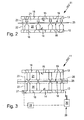
- FIG. 2 shows a second embodiment of the air bearing device 11 according to the invention. It differs from the in FIG. 1
- the bearing body 12, 13 according to the second embodiment consist of porous material, such as ceramic material, which is permeable to air, wherein in the bearing bodies 12, 13 due to the porosity a Variety of outflow channels 16 are formed, which open at the bearing surfaces 14, 15 of the bearing body 12, 13. Due to the large number of outflow channels 16, a type of microchannel system is thus formed which ensures that compressed air exits substantially uniformly over the bearing surfaces 14, 15 and thus forms a large-area and uniform air cushion.
- FIG. 2 is also roughly schematically the change of the gap width in Sequence of a pressure change or change in volume flow shown. The thicker arrows correspond to the increased pressure or increased volume flow.
- FIG. 3 a third embodiment of the air bearing device 11 according to the invention shown.
- this third embodiment is consistent with the second embodiment described above.
- an adjusting device 29 is provided, which has an actuator 30 which is coupled via transmission means with the associated bearing body 12.
- an electric spindle drive is shown here purely by way of example, the spindle is also suitable for very short-stroke translational positioning movements.
- the actuator 30 is signal-wise coupled to the control device 28 and receives control signals, whereby the actuator 30 is caused to change the distance between the two bearing surfaces 12, 13. This may be the case, for example, if first FPD screens having an average thickness of about 0.7 mm are transported and then a batch change takes place on, for example, solar panels, which typically have a thickness of 3.2 mm. The distance between the two bearing surfaces 14, 15 to each other must be increased accordingly. Furthermore, an automatic compensation of workpiece tolerances is also possible here.
- the substrate body for example a solar panel or an FPD screen
- the substrate body moves first in the space between the two bearing bodies 12, 13 a.
- Compressed air already flows out of the outflow ducts 16, which bounces against the substrate upper side or underside, that is to say against the mating surfaces 18, 19.
- an air cushion 20, 21 is formed between the upper side of the substrate and the second bearing surface 15 and the substrate lower side and the first bearing surface 14, which pneumatically clamp the substrate body 25 in the desired height position between the two bearing bodies.
- the substrate body 25 is then transported through the air bearing device 11 and then passes either to another processing station, such as a laser station or in the next air bearing device 11.
- a signal is output to the control device 28, which in turn sends a control signal to the volume flow controller or according to FIG. 1
- Pressure regulator outputs, which changes the state of the formed between the substrate bottom and the first bearing surface 14 air cushion such that the substrate top comes back to the exact desired position, which correlates with the desired gap width.
- one of the bearing bodies as described in FIG. 3 shown be movably guided by means of an adjusting device 29, so that can be changed by changing the distance between the two bearing bodies on substrate body of different thicknesses.
Landscapes
- Magnetic Bearings And Hydrostatic Bearings (AREA)
Claims (7)
- Dispositif à palier à air, comprenant au moins un corps de palier (12, 13), qui présente une pluralité de canaux d'évacuation par écoulement (16) débouchant au niveau d'une face de palier (14, 15) du corps de palier (12, 13), à travers lesquels de l'air comprimé peut être acheminé, sachant que la face de palier (14, 15) coopère avec une face complémentaire (18, 19), tournée vers elle, d'un corps de substrat (25) de telle manière qu'un coussin d'air (20, 21) peut être produit par l'air comprimé évacué par écoulement entre la face de palier (14, 15) et la face complémentaire (18, 19), lequel coussin d'air crée un intervalle de palier (22, 23), les deux faces étant de ce fait disposées à distance l'une de l'autre conformément à une largeur d'intervalle de l'intervalle de palier (22, 23), sachant que le corps de palier (12, 13) fait partie intégrante en tant que premier corps de palier (12) d'un dispositif de serrage (40) pneumatique, qui présente, en complément, un deuxième corps de palier (13) pourvu d'une pluralité de canaux d'évacuation par écoulement (16) débouchant au niveau d'une deuxième face de palier (15) du deuxième corps de palier (13), sachant que les deux faces de palier (14, 15) se font face mutuellement et que le corps de substrat (25) peut être positionné entre les faces de palier (14, 15) de telle manière qu'il peut être immobilisé par serrage de manière pneumatique par les deux coussins d'air (20, 21) produits entre les faces de palier (14,15) et les faces complémentaires (18, 19) respectivement associées, de part et d'autre du corps de substrat (25), dans la position souhaitée, en direction perpendiculairement des faces de palier (14, 15), caractérisé en ce qu'un dispositif de réglage (29) servant à régler diverses distances entre les faces de palier (14, 15) des corps de palier (12, 13) est associé à au moins un des corps de palier (12, 13), sachant que le dispositif de réglage présente un entraînement de réglage, qui est couplé en déplacement au corps de palier (12, 13) associé par l'intermédiaire de moyens de transmission.
- Dispositif à palier à air selon la revendication 1, caractérisé en ce qu'un régulateur de pression (24) et/ou un régulateur de flux volumique servant à régler différentes pressions et/ou flux volumiques de l'air comprimé circulant à travers les canaux d'évacuation par écoulement (16) et servant, ce faisant, à régler diverses largeurs d'intervalle est associé à au moins un des corps de palier (12, 13).
- Dispositif à palier à air selon la revendication 1, caractérisé par un dispositif de surveillance des largeurs d'intervalle (26) servant à surveiller les largeurs d'intervalle des intervalles de palier (22, 23).
- Dispositif à palier à air selon la revendication 3, caractérisé en ce que le dispositif de surveillance des largeurs d'intervalle (26) est réalisé de telle manière qu'une surveillance de la largeur d'intervalle est possible indépendamment de l'air comprimé produisant le coussin d'air (20, 21).
- Dispositif à palier à air selon la revendication 3 ou 4, caractérisé en ce que le dispositif de surveillance des largeurs d'intervalle (26) présente au moins un capteur de surveillance (27), au moyen duquel des largeurs d'intervalle réelles peuvent être détectées et qui, en présence d'une valeur inférieure à une largeur d'intervalle minimale enregistrée, émet un signal d'erreur.
- Dispositif à palier à air selon la revendication 5, caractérisé en ce que le capteur de surveillance est réalisé sous la forme d'un capteur d'entrefer.
- Dispositif à palier à air selon la revendication 2, 3 et 6, caractérisé en ce qu'est prévu un dispositif de commande (28), qui est couplé d'une part au dispositif de surveillance des largeurs d'intervalle (26) et d'autre part à l'entraînement de réglage (30) et/ou au régulateur de pression (24) et/ou au régulateur de flux volumique servant à régler de manière commandée les largeurs d'intervalle des intervalles de palier (22, 23).
Applications Claiming Priority (2)
| Application Number | Priority Date | Filing Date | Title |
|---|---|---|---|
| DE102010024263A DE102010024263A1 (de) | 2010-06-18 | 2010-06-18 | Luftlagereinrichtung |
| PCT/EP2011/002752 WO2011157363A1 (fr) | 2010-06-18 | 2011-06-04 | Dispositif à palier à air |
Publications (2)
| Publication Number | Publication Date |
|---|---|
| EP2556005A1 EP2556005A1 (fr) | 2013-02-13 |
| EP2556005B1 true EP2556005B1 (fr) | 2015-04-01 |
Family
ID=44352172
Family Applications (1)
| Application Number | Title | Priority Date | Filing Date |
|---|---|---|---|
| EP11723887.3A Not-in-force EP2556005B1 (fr) | 2010-06-18 | 2011-06-04 | Dispositif de coussin d'air |
Country Status (4)
| Country | Link |
|---|---|
| EP (1) | EP2556005B1 (fr) |
| DE (1) | DE102010024263A1 (fr) |
| TW (1) | TW201209301A (fr) |
| WO (1) | WO2011157363A1 (fr) |
Cited By (1)
| Publication number | Priority date | Publication date | Assignee | Title |
|---|---|---|---|---|
| CN109277788A (zh) * | 2018-09-10 | 2019-01-29 | 东莞市松研智达工业设计有限公司 | 具有垫片拿取与装配功能的机械人系统 |
Families Citing this family (2)
| Publication number | Priority date | Publication date | Assignee | Title |
|---|---|---|---|---|
| DE102017006584A1 (de) | 2017-01-17 | 2018-07-19 | 3D-Micromac Ag | Verfahren und Vorrichtung zum berührungslosen Werkstücktransport |
| CN114244011B (zh) * | 2021-11-19 | 2023-05-26 | 青岛海尔空调电子有限公司 | 压缩机及制冷系统 |
Citations (1)
| Publication number | Priority date | Publication date | Assignee | Title |
|---|---|---|---|---|
| US20100209082A1 (en) * | 2008-05-30 | 2010-08-19 | Alta Devices, Inc. | Heating lamp system |
Family Cites Families (12)
| Publication number | Priority date | Publication date | Assignee | Title |
|---|---|---|---|---|
| GB982855A (en) * | 1961-06-28 | 1965-02-10 | Ibm | Element supporting apparatus embodying a fluid bearing e.g. in information storage devices |
| US3867725A (en) * | 1973-10-01 | 1975-02-18 | Ibm | Rotating head apparatus including a thrust gas bearing |
| US6027112A (en) * | 1998-03-02 | 2000-02-22 | Xerox Corporation | Adaptive multiagent control system for controlling object motion with smart matter |
| US6781684B1 (en) * | 2000-11-07 | 2004-08-24 | Donald L. Ekhoff | Workpiece levitation using alternating positive and negative pressure flows |
| JP3949910B2 (ja) * | 2001-07-05 | 2007-07-25 | 株式会社ミツトヨ | エアーベアリングを用いた駆動装置 |
| TWI222423B (en) * | 2001-12-27 | 2004-10-21 | Orbotech Ltd | System and methods for conveying and transporting levitated articles |
| ATE384964T1 (de) | 2002-07-02 | 2008-02-15 | Agfa Gevaert Healthcare Gmbh | Vorrichtung und verfahren zum auslesen von in einer speicherschicht abgespeicherter information |
| KR101931923B1 (ko) * | 2003-06-19 | 2018-12-21 | 가부시키가이샤 니콘 | 노광 장치 및 디바이스 제조방법 |
| KR20070006768A (ko) * | 2004-03-17 | 2007-01-11 | 코레플로우 사이언티픽 솔루션스 리미티드 | 비접촉 열 플랫폼 |
| WO2006052919A1 (fr) | 2004-11-08 | 2006-05-18 | New Way Machine Components, Inc. | Palier a air poreux exempt de contact et dispositif d'aplanissement du verre |
| DE102005007079B4 (de) | 2005-02-16 | 2007-01-11 | Eitzenberger Luftlagertechnik Gmbh | Luftgelagertes Portal |
| WO2008035324A2 (fr) * | 2006-09-19 | 2008-03-27 | Coreflow Scientific Solutions Ltd | Appareil pour traitement de fluide |
-
2010
- 2010-06-18 DE DE102010024263A patent/DE102010024263A1/de not_active Ceased
-
2011
- 2011-06-04 EP EP11723887.3A patent/EP2556005B1/fr not_active Not-in-force
- 2011-06-04 WO PCT/EP2011/002752 patent/WO2011157363A1/fr not_active Ceased
- 2011-06-16 TW TW100120975A patent/TW201209301A/zh unknown
Patent Citations (1)
| Publication number | Priority date | Publication date | Assignee | Title |
|---|---|---|---|---|
| US20100209082A1 (en) * | 2008-05-30 | 2010-08-19 | Alta Devices, Inc. | Heating lamp system |
Cited By (2)
| Publication number | Priority date | Publication date | Assignee | Title |
|---|---|---|---|---|
| CN109277788A (zh) * | 2018-09-10 | 2019-01-29 | 东莞市松研智达工业设计有限公司 | 具有垫片拿取与装配功能的机械人系统 |
| CN109277788B (zh) * | 2018-09-10 | 2020-05-05 | 烟台石川密封科技股份有限公司 | 具有垫片拿取与装配功能的机械人系统 |
Also Published As
| Publication number | Publication date |
|---|---|
| EP2556005A1 (fr) | 2013-02-13 |
| DE102010024263A1 (de) | 2011-12-22 |
| TW201209301A (en) | 2012-03-01 |
| WO2011157363A1 (fr) | 2011-12-22 |
Similar Documents
| Publication | Publication Date | Title |
|---|---|---|
| EP1753679B1 (fr) | Etabli de reception d'une piece et procede de traitement d'une piece sur un tel etabli | |
| EP2657000B1 (fr) | Dispositif pour la production de produits plats et méthode pour régler le dispositif | |
| DE2731704A1 (de) | Praezisionstisch fuer die ausfuehrung einer zweidimensionalen bewegung | |
| DE102008030417A1 (de) | Verfahren und Anlage zur Herstellung von Werkstoffplatten, wie Span, Schnitzel-, Faser- oder ähnlichen Holzwerkstoffplatten sowie Kunststoffplatten | |
| DE69106165T2 (de) | Führungsvorrichtung. | |
| CH660805A5 (de) | Vorrichtung zur feineinstellung einer verschiebung und/oder drehung. | |
| AT501192B1 (de) | Vorrichtung zum transportieren und stützen tafelförmiger gegenstände, insbesondere glastafeln | |
| EP1097332A1 (fr) | Paroi de canal d'ecoulement | |
| AT501784B1 (de) | Plattenaufteilsäge | |
| WO2011157363A1 (fr) | Dispositif à palier à air | |
| DE102016101695B4 (de) | Positioniervorrichtung mit einer über Luftlager lateral verschiebbaren und ausgerichteten Halteplatte | |
| WO2007028404A1 (fr) | Dispositif destine a recevoir des materiaux sous forme de plaques pour au moins un processus de separation | |
| EP1382415A1 (fr) | Amortissement actif de vibrations dans une machine-outil | |
| DD256612A3 (de) | Druckbalken fuer langbandschleifmaschine | |
| EP2634124B1 (fr) | Procédé et agencement destinés au transport de matériaux | |
| WO2012062296A2 (fr) | Dispositif de structuration très précise de modules de cellules solaires à couches minces | |
| DE10047385C2 (de) | Verfahren und Vorrichtung zur Bearbeitung von fortlaufend bewegten Werkstücken | |
| EP4452794A1 (fr) | Unité flottante | |
| EP2958752B1 (fr) | Dispositif de traitement de surface | |
| DE202004002258U1 (de) | Linearbewegungssystem | |
| WO1989012014A1 (fr) | Agencement a couches de milieu d'ecoulement pour positionnement et/ou transport de charges isolees | |
| WO2004062901A1 (fr) | Dispositif de guidage d'outil | |
| EP1583619A2 (fr) | Module de guidage plat destine notamment a une cage de laminoir, et procede de laminage d'une cage de laminoir equipee d'un module de guidage plat | |
| DE2606601A1 (de) | Transportvorrichtung, insbesondere fuer spanende werkzeugmaschinen | |
| EP0232794B1 (fr) | Transducteur électrodynamique |
Legal Events
| Date | Code | Title | Description |
|---|---|---|---|
| PUAI | Public reference made under article 153(3) epc to a published international application that has entered the european phase |
Free format text: ORIGINAL CODE: 0009012 |
|
| 17P | Request for examination filed |
Effective date: 20121108 |
|
| AK | Designated contracting states |
Kind code of ref document: A1 Designated state(s): AL AT BE BG CH CY CZ DE DK EE ES FI FR GB GR HR HU IE IS IT LI LT LU LV MC MK MT NL NO PL PT RO RS SE SI SK SM TR |
|
| RIN1 | Information on inventor provided before grant (corrected) |
Inventor name: SIEBER, MANUEL Inventor name: BIDMON, MICHAEL Inventor name: PATTORA, RONNY Inventor name: KEICHER, CHRISTOPH |
|
| DAX | Request for extension of the european patent (deleted) | ||
| 17Q | First examination report despatched |
Effective date: 20140404 |
|
| GRAP | Despatch of communication of intention to grant a patent |
Free format text: ORIGINAL CODE: EPIDOSNIGR1 |
|
| INTG | Intention to grant announced |
Effective date: 20141106 |
|
| GRAS | Grant fee paid |
Free format text: ORIGINAL CODE: EPIDOSNIGR3 |
|
| GRAA | (expected) grant |
Free format text: ORIGINAL CODE: 0009210 |
|
| AK | Designated contracting states |
Kind code of ref document: B1 Designated state(s): AL AT BE BG CH CY CZ DE DK EE ES FI FR GB GR HR HU IE IS IT LI LT LU LV MC MK MT NL NO PL PT RO RS SE SI SK SM TR |
|
| REG | Reference to a national code |
Ref country code: GB Ref legal event code: FG4D Free format text: NOT ENGLISH |
|
| REG | Reference to a national code |
Ref country code: CH Ref legal event code: EP |
|
| REG | Reference to a national code |
Ref country code: IE Ref legal event code: FG4D Free format text: LANGUAGE OF EP DOCUMENT: GERMAN |
|
| REG | Reference to a national code |
Ref country code: DE Ref legal event code: R096 Ref document number: 502011006454 Country of ref document: DE Effective date: 20150513 |
|
| REG | Reference to a national code |
Ref country code: AT Ref legal event code: REF Ref document number: 718942 Country of ref document: AT Kind code of ref document: T Effective date: 20150515 |
|
| REG | Reference to a national code |
Ref country code: FR Ref legal event code: PLFP Year of fee payment: 5 |
|
| PGFP | Annual fee paid to national office [announced via postgrant information from national office to epo] |
Ref country code: GB Payment date: 20150605 Year of fee payment: 5 |
|
| REG | Reference to a national code |
Ref country code: NL Ref legal event code: VDEP Effective date: 20150401 |
|
| PGFP | Annual fee paid to national office [announced via postgrant information from national office to epo] |
Ref country code: FR Payment date: 20150623 Year of fee payment: 5 |
|
| REG | Reference to a national code |
Ref country code: LT Ref legal event code: MG4D |
|
| PG25 | Lapsed in a contracting state [announced via postgrant information from national office to epo] |
Ref country code: NL Free format text: LAPSE BECAUSE OF FAILURE TO SUBMIT A TRANSLATION OF THE DESCRIPTION OR TO PAY THE FEE WITHIN THE PRESCRIBED TIME-LIMIT Effective date: 20150401 |
|
| PG25 | Lapsed in a contracting state [announced via postgrant information from national office to epo] |
Ref country code: LT Free format text: LAPSE BECAUSE OF FAILURE TO SUBMIT A TRANSLATION OF THE DESCRIPTION OR TO PAY THE FEE WITHIN THE PRESCRIBED TIME-LIMIT Effective date: 20150401 Ref country code: PT Free format text: LAPSE BECAUSE OF FAILURE TO SUBMIT A TRANSLATION OF THE DESCRIPTION OR TO PAY THE FEE WITHIN THE PRESCRIBED TIME-LIMIT Effective date: 20150803 Ref country code: CZ Free format text: LAPSE BECAUSE OF FAILURE TO SUBMIT A TRANSLATION OF THE DESCRIPTION OR TO PAY THE FEE WITHIN THE PRESCRIBED TIME-LIMIT Effective date: 20150401 Ref country code: NO Free format text: LAPSE BECAUSE OF FAILURE TO SUBMIT A TRANSLATION OF THE DESCRIPTION OR TO PAY THE FEE WITHIN THE PRESCRIBED TIME-LIMIT Effective date: 20150701 Ref country code: FI Free format text: LAPSE BECAUSE OF FAILURE TO SUBMIT A TRANSLATION OF THE DESCRIPTION OR TO PAY THE FEE WITHIN THE PRESCRIBED TIME-LIMIT Effective date: 20150401 Ref country code: HR Free format text: LAPSE BECAUSE OF FAILURE TO SUBMIT A TRANSLATION OF THE DESCRIPTION OR TO PAY THE FEE WITHIN THE PRESCRIBED TIME-LIMIT Effective date: 20150401 Ref country code: ES Free format text: LAPSE BECAUSE OF FAILURE TO SUBMIT A TRANSLATION OF THE DESCRIPTION OR TO PAY THE FEE WITHIN THE PRESCRIBED TIME-LIMIT Effective date: 20150401 |
|
| PG25 | Lapsed in a contracting state [announced via postgrant information from national office to epo] |
Ref country code: RS Free format text: LAPSE BECAUSE OF FAILURE TO SUBMIT A TRANSLATION OF THE DESCRIPTION OR TO PAY THE FEE WITHIN THE PRESCRIBED TIME-LIMIT Effective date: 20150401 Ref country code: LV Free format text: LAPSE BECAUSE OF FAILURE TO SUBMIT A TRANSLATION OF THE DESCRIPTION OR TO PAY THE FEE WITHIN THE PRESCRIBED TIME-LIMIT Effective date: 20150401 Ref country code: IS Free format text: LAPSE BECAUSE OF FAILURE TO SUBMIT A TRANSLATION OF THE DESCRIPTION OR TO PAY THE FEE WITHIN THE PRESCRIBED TIME-LIMIT Effective date: 20150801 Ref country code: GR Free format text: LAPSE BECAUSE OF FAILURE TO SUBMIT A TRANSLATION OF THE DESCRIPTION OR TO PAY THE FEE WITHIN THE PRESCRIBED TIME-LIMIT Effective date: 20150702 |
|
| PGFP | Annual fee paid to national office [announced via postgrant information from national office to epo] |
Ref country code: IT Payment date: 20150713 Year of fee payment: 5 |
|
| REG | Reference to a national code |
Ref country code: DE Ref legal event code: R097 Ref document number: 502011006454 Country of ref document: DE |
|
| PG25 | Lapsed in a contracting state [announced via postgrant information from national office to epo] |
Ref country code: MC Free format text: LAPSE BECAUSE OF FAILURE TO SUBMIT A TRANSLATION OF THE DESCRIPTION OR TO PAY THE FEE WITHIN THE PRESCRIBED TIME-LIMIT Effective date: 20150401 Ref country code: EE Free format text: LAPSE BECAUSE OF FAILURE TO SUBMIT A TRANSLATION OF THE DESCRIPTION OR TO PAY THE FEE WITHIN THE PRESCRIBED TIME-LIMIT Effective date: 20150401 Ref country code: DK Free format text: LAPSE BECAUSE OF FAILURE TO SUBMIT A TRANSLATION OF THE DESCRIPTION OR TO PAY THE FEE WITHIN THE PRESCRIBED TIME-LIMIT Effective date: 20150401 |
|
| REG | Reference to a national code |
Ref country code: CH Ref legal event code: PL |
|
| PLBE | No opposition filed within time limit |
Free format text: ORIGINAL CODE: 0009261 |
|
| STAA | Information on the status of an ep patent application or granted ep patent |
Free format text: STATUS: NO OPPOSITION FILED WITHIN TIME LIMIT |
|
| PG25 | Lapsed in a contracting state [announced via postgrant information from national office to epo] |
Ref country code: SK Free format text: LAPSE BECAUSE OF FAILURE TO SUBMIT A TRANSLATION OF THE DESCRIPTION OR TO PAY THE FEE WITHIN THE PRESCRIBED TIME-LIMIT Effective date: 20150401 Ref country code: PL Free format text: LAPSE BECAUSE OF FAILURE TO SUBMIT A TRANSLATION OF THE DESCRIPTION OR TO PAY THE FEE WITHIN THE PRESCRIBED TIME-LIMIT Effective date: 20150401 Ref country code: RO Free format text: LAPSE BECAUSE OF NON-PAYMENT OF DUE FEES Effective date: 20150401 Ref country code: LU Free format text: LAPSE BECAUSE OF FAILURE TO SUBMIT A TRANSLATION OF THE DESCRIPTION OR TO PAY THE FEE WITHIN THE PRESCRIBED TIME-LIMIT Effective date: 20150604 |
|
| 26N | No opposition filed |
Effective date: 20160105 |
|
| REG | Reference to a national code |
Ref country code: IE Ref legal event code: MM4A |
|
| PG25 | Lapsed in a contracting state [announced via postgrant information from national office to epo] |
Ref country code: CH Free format text: LAPSE BECAUSE OF NON-PAYMENT OF DUE FEES Effective date: 20150630 Ref country code: IE Free format text: LAPSE BECAUSE OF NON-PAYMENT OF DUE FEES Effective date: 20150604 Ref country code: LI Free format text: LAPSE BECAUSE OF NON-PAYMENT OF DUE FEES Effective date: 20150630 |
|
| PG25 | Lapsed in a contracting state [announced via postgrant information from national office to epo] |
Ref country code: SI Free format text: LAPSE BECAUSE OF FAILURE TO SUBMIT A TRANSLATION OF THE DESCRIPTION OR TO PAY THE FEE WITHIN THE PRESCRIBED TIME-LIMIT Effective date: 20150401 |
|
| PGFP | Annual fee paid to national office [announced via postgrant information from national office to epo] |
Ref country code: DE Payment date: 20160603 Year of fee payment: 6 |
|
| PG25 | Lapsed in a contracting state [announced via postgrant information from national office to epo] |
Ref country code: MT Free format text: LAPSE BECAUSE OF FAILURE TO SUBMIT A TRANSLATION OF THE DESCRIPTION OR TO PAY THE FEE WITHIN THE PRESCRIBED TIME-LIMIT Effective date: 20150401 |
|
| GBPC | Gb: european patent ceased through non-payment of renewal fee |
Effective date: 20160604 |
|
| REG | Reference to a national code |
Ref country code: FR Ref legal event code: ST Effective date: 20170228 |
|
| PG25 | Lapsed in a contracting state [announced via postgrant information from national office to epo] |
Ref country code: FR Free format text: LAPSE BECAUSE OF NON-PAYMENT OF DUE FEES Effective date: 20160630 |
|
| PG25 | Lapsed in a contracting state [announced via postgrant information from national office to epo] |
Ref country code: GB Free format text: LAPSE BECAUSE OF NON-PAYMENT OF DUE FEES Effective date: 20160604 Ref country code: SM Free format text: LAPSE BECAUSE OF FAILURE TO SUBMIT A TRANSLATION OF THE DESCRIPTION OR TO PAY THE FEE WITHIN THE PRESCRIBED TIME-LIMIT Effective date: 20150401 Ref country code: BG Free format text: LAPSE BECAUSE OF FAILURE TO SUBMIT A TRANSLATION OF THE DESCRIPTION OR TO PAY THE FEE WITHIN THE PRESCRIBED TIME-LIMIT Effective date: 20150401 Ref country code: HU Free format text: LAPSE BECAUSE OF FAILURE TO SUBMIT A TRANSLATION OF THE DESCRIPTION OR TO PAY THE FEE WITHIN THE PRESCRIBED TIME-LIMIT; INVALID AB INITIO Effective date: 20110604 |
|
| PG25 | Lapsed in a contracting state [announced via postgrant information from national office to epo] |
Ref country code: IT Free format text: LAPSE BECAUSE OF NON-PAYMENT OF DUE FEES Effective date: 20160604 Ref country code: CY Free format text: LAPSE BECAUSE OF FAILURE TO SUBMIT A TRANSLATION OF THE DESCRIPTION OR TO PAY THE FEE WITHIN THE PRESCRIBED TIME-LIMIT Effective date: 20150401 Ref country code: SE Free format text: LAPSE BECAUSE OF FAILURE TO SUBMIT A TRANSLATION OF THE DESCRIPTION OR TO PAY THE FEE WITHIN THE PRESCRIBED TIME-LIMIT Effective date: 20150401 |
|
| PG25 | Lapsed in a contracting state [announced via postgrant information from national office to epo] |
Ref country code: BE Free format text: LAPSE BECAUSE OF NON-PAYMENT OF DUE FEES Effective date: 20150630 Ref country code: AT Free format text: LAPSE BECAUSE OF FAILURE TO SUBMIT A TRANSLATION OF THE DESCRIPTION OR TO PAY THE FEE WITHIN THE PRESCRIBED TIME-LIMIT Effective date: 20150401 |
|
| REG | Reference to a national code |
Ref country code: AT Ref legal event code: MM01 Ref document number: 718942 Country of ref document: AT Kind code of ref document: T Effective date: 20160604 |
|
| PG25 | Lapsed in a contracting state [announced via postgrant information from national office to epo] |
Ref country code: TR Free format text: LAPSE BECAUSE OF FAILURE TO SUBMIT A TRANSLATION OF THE DESCRIPTION OR TO PAY THE FEE WITHIN THE PRESCRIBED TIME-LIMIT Effective date: 20150401 |
|
| PG25 | Lapsed in a contracting state [announced via postgrant information from national office to epo] |
Ref country code: AT Free format text: LAPSE BECAUSE OF FAILURE TO SUBMIT A TRANSLATION OF THE DESCRIPTION OR TO PAY THE FEE WITHIN THE PRESCRIBED TIME-LIMIT Effective date: 20160604 |
|
| REG | Reference to a national code |
Ref country code: DE Ref legal event code: R119 Ref document number: 502011006454 Country of ref document: DE |
|
| PG25 | Lapsed in a contracting state [announced via postgrant information from national office to epo] |
Ref country code: DE Free format text: LAPSE BECAUSE OF NON-PAYMENT OF DUE FEES Effective date: 20180103 |
|
| PG25 | Lapsed in a contracting state [announced via postgrant information from national office to epo] |
Ref country code: MK Free format text: LAPSE BECAUSE OF FAILURE TO SUBMIT A TRANSLATION OF THE DESCRIPTION OR TO PAY THE FEE WITHIN THE PRESCRIBED TIME-LIMIT Effective date: 20150401 |
|
| PG25 | Lapsed in a contracting state [announced via postgrant information from national office to epo] |
Ref country code: AL Free format text: LAPSE BECAUSE OF FAILURE TO SUBMIT A TRANSLATION OF THE DESCRIPTION OR TO PAY THE FEE WITHIN THE PRESCRIBED TIME-LIMIT Effective date: 20150401 |