EP2556740A1 - Schnittanlage zum Abschneiden von Pflanzen mit senkrechten Stängeln, wie beispielsweise Hanf, und Mähdrescher mit fahrbarem Untergestell, das am Vorderteil mit einer solchen Schnittanlage ausgestattet ist - Google Patents
Schnittanlage zum Abschneiden von Pflanzen mit senkrechten Stängeln, wie beispielsweise Hanf, und Mähdrescher mit fahrbarem Untergestell, das am Vorderteil mit einer solchen Schnittanlage ausgestattet ist Download PDFInfo
- Publication number
- EP2556740A1 EP2556740A1 EP12172868A EP12172868A EP2556740A1 EP 2556740 A1 EP2556740 A1 EP 2556740A1 EP 12172868 A EP12172868 A EP 12172868A EP 12172868 A EP12172868 A EP 12172868A EP 2556740 A1 EP2556740 A1 EP 2556740A1
- Authority
- EP
- European Patent Office
- Prior art keywords
- cutting
- cutting device
- rolling
- chassis
- installation
- Prior art date
- Legal status (The legal status is an assumption and is not a legal conclusion. Google has not performed a legal analysis and makes no representation as to the accuracy of the status listed.)
- Withdrawn
Links
- 238000005520 cutting process Methods 0.000 title claims abstract description 235
- 238000009434 installation Methods 0.000 title claims abstract description 30
- 241000196324 Embryophyta Species 0.000 title claims description 20
- 244000025254 Cannabis sativa Species 0.000 title claims description 12
- 235000012766 Cannabis sativa ssp. sativa var. sativa Nutrition 0.000 title claims description 12
- 235000012765 Cannabis sativa ssp. sativa var. spontanea Nutrition 0.000 title claims description 12
- 235000009120 camo Nutrition 0.000 title claims description 12
- 235000005607 chanvre indien Nutrition 0.000 title claims description 12
- 239000011487 hemp Substances 0.000 title claims description 12
- 238000011084 recovery Methods 0.000 claims abstract description 9
- 230000005484 gravity Effects 0.000 claims abstract description 4
- 238000004891 communication Methods 0.000 claims abstract description 3
- 238000005096 rolling process Methods 0.000 claims description 67
- 238000007599 discharging Methods 0.000 claims description 9
- 238000006073 displacement reaction Methods 0.000 claims description 7
- 230000008878 coupling Effects 0.000 claims description 3
- 238000010168 coupling process Methods 0.000 claims description 3
- 238000005859 coupling reaction Methods 0.000 claims description 3
- 235000013339 cereals Nutrition 0.000 description 7
- 238000003306 harvesting Methods 0.000 description 6
- 238000010008 shearing Methods 0.000 description 3
- 230000006978 adaptation Effects 0.000 description 2
- 230000005540 biological transmission Effects 0.000 description 2
- 238000000926 separation method Methods 0.000 description 2
- 239000010902 straw Substances 0.000 description 2
- 229910000831 Steel Inorganic materials 0.000 description 1
- 241000219094 Vitaceae Species 0.000 description 1
- 108010066114 cabin-2 Proteins 0.000 description 1
- 235000021021 grapes Nutrition 0.000 description 1
- 230000007257 malfunction Effects 0.000 description 1
- 230000009347 mechanical transmission Effects 0.000 description 1
- 238000000034 method Methods 0.000 description 1
- 238000003892 spreading Methods 0.000 description 1
- 239000010959 steel Substances 0.000 description 1
- 238000003860 storage Methods 0.000 description 1
Images



Classifications
-
- A—HUMAN NECESSITIES
- A01—AGRICULTURE; FORESTRY; ANIMAL HUSBANDRY; HUNTING; TRAPPING; FISHING
- A01D—HARVESTING; MOWING
- A01D45/00—Harvesting of standing crops
- A01D45/06—Harvesting of standing crops of flax or similar fibrous plants
- A01D45/065—Harvesting of standing crops of flax or similar fibrous plants of fibrous plants other than flax, e.g. ramie, sisal, hemp, jute, Spanish grass, raffia
Definitions
- the present invention relates to a cutting plant for the cutting of plants with a vertical stem, such as hemp, grown in fields, as well as a combine harvester whose rolling frame is equipped at the front of a cutting plant of the type supra.
- An object of the present invention is therefore to provide a positionable cutting installation on a rolling combine harvester whose design allows an application to harvest hemp.
- Another object of the present invention is to provide a positionable cutting installation on a rolling combine combine whose design allows adaptation to high-profile rods of various profiles.
- the subject of the invention is a cutting installation for cutting vertically-stemmed plants, such as hemp, grown in fields, said installation being of the type that can be positioned at the front of the rolling chassis, equipped at least with conveying means and threshing means of the conveyed products, a combine harvester, said cutting installation comprising a cutting device, said lower, and a cutting device, said upper, positionable above the lower cutting device , in the coupled state of the cutting devices to the rolling frame of the combine, means for driving up and down the upper cutting device, and recovery and discharge means positionable in series with the device of lower cut, the so-called upper cutting device, able to feed the products of the conveying means of the rolling chassis of the combine, being equipped, in its so-called front part, with a cutter bar defining a cutting line capable of spreading transversely to the direction of movement of the rolling frame of the combine and, in its so-called rear part, of a cutting apron provided with at least one opening for evacuating the heads of rods cut by the
- the cutting line of the lower cutting device and in that the recovery and discharge means positionable in series with the lower cutting device comprise a chamber, called grinding chamber, housing at least one cutting function rotor, d rotation axis substantially parallel to the cutting line of the lower cutting device, said enclosure being, for its communication with the discharge opening of the device of lower section, provided with an inlet opening and, for its emptying, an outlet opening arranged, preferably at a location of the enclosure adapted to allow a gravity ground removal of the contents of the enclosure .
- This design of the raising and lowering drive means makes it possible to vary within a wide range the distance of the cutting lines of the cutting devices in a vertical direction, which allows adaptation of the cutting installation. to tall stems or low height.
- said structure is a mobile structure articulately couplable to the rolling chassis of the combine harvester.
- said structure comprises, for its coupling with the rolling chassis of the combine harvester, on the one hand, pivotally connected connection means positioned or positionable at the so-called lower end of the or the uprights and forming, at the positioned state, a pivot axis connection substantially parallel to the cutting line of the upper cutting device, on the other hand, at least one actuator, such as a jack, adapted to drive in pivotal displacement said structure in function the desired relative positioning between the cutting lines of the upper and lower cutting devices.
- pivotally connected connection means positioned or positionable at the so-called lower end of the or the uprights and forming, at the positioned state, a pivot axis connection substantially parallel to the cutting line of the upper cutting device, on the other hand, at least one actuator, such as a jack, adapted to drive in pivotal displacement said structure in function the desired relative positioning between the cutting lines of the upper and lower cutting devices.
- This pivotal movement of the structure makes it possible to vary within a wide range the distance between the cutting lines of the cutting devices in a so-called front-rear direction parallel to the line of advance or displacement of the frame of the combine, or the longitudinal axis of the combine's rolling frame, in the coupled condition from the cutting plant to the combine.
- the displacement drive means of said cut products to said at least one discharge opening of the lower cutting device are in the form of toothed discs, at least some of which form with a cutting disc of the lower cutting device with which they are associated, a stack of disks. At least some of the toothed discs frame, as stacks of discs, the discharge opening of the lower cutter.
- said opening for evacuating the lower cutting device is formed in the so-called bottom portion of a cutting apron whose flanks are equipped with a feed screw positioned in parallel. and above the upper edge of each side, at a notch in said sidewall.
- the subject of the invention is also a combine harvester of the type comprising a rolling frame equipped with at least one conveying means and threshing means for the conveyed products and, in front of said rolling frame, taken in the advancing direction of said chassis, a cutting plant plant with vertical stems, characterized in that said cutting installation is in accordance with that described above, in that the so-called grinding chamber is disposed below the conveying means of the rolling frame, in that the discharge opening of the upper section is positioned above and vertically or immediately in front of conveying means taken in the direction of advance of the combine, and in that the upper cutting device and its drive means is mounted and drop form a mobile assembly pivotally mounted about an axis substantially parallel to the cutting lines of the cutting devices.
- the cutting installation 1 which is the subject of the invention, is more particularly intended for the cutting of plants with a vertical stem, such as hemp, even if it can also be applied to the cutting of cereals. or other plants.
- This cutting installation 1 is positionable at the front of the chassis 2 rolling of a combine.
- This chassis 2 of the combine harvester is equipped with two front wheels 203 and two rear wheels 203 and means 201 for conveying harvested products, these means 201 for conveying being generally made using at least one conveyor belt. unending.
- This chassis 2 rolling still comprises 202 beater means formed for example of a drummer and a concave. Downstream of these threshing means 202, the chassis 2 can be equipped with separating means such as means for shaking the grains of the rod and storage means for said grains in the separated state, the remainder of the separation, can be deposited on the ground.
- separating means such as means for shaking the grains of the rod and storage means for said grains in the separated state, the remainder of the separation, can be deposited on the ground.
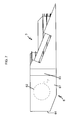
- This cutting installation 1, intended to be coupled to the rolling chassis 2 of the combine harvester at the front of the latter, comprises two cutting devices 3, 4 positioned one above the other, at the coupled state of the cutting plant to the rolling chassis 2 of the combine.
- the cutting device positioned at the top, that is to say at a higher level than the other cutting device, is shown at 4 in the figures and called upper cutting device; the cutter positioned furthest beneath, i.e. at a lower level than the other cutter, and shown at 3 in the figures, is called the lower cutter.
- These cutting devices have an elongated shape. Their longitudinal axis extends transversely to the direction of movement of the chassis 2 rolling along a width of the band traversed by the combine in the coupled state of the cutting devices to the rolling frame 2 of said combine.
- the installation also comprises drive means 5 for raising and lowering the upper cutting device 3. These drive means 5 up and down are interposable between upper cutting device and chassis 2 rolling.
- the installation also comprises means 6 for recovering and discharging the products, in particular rods cut by the lower cutting device 3.
- These means 6 of recovery and evacuation are arranged in series with the device 3 of lower cut, that is to say immediately behind the device 3 of lower cutter, taken in the direction of advance of the combine harvester , to recover the stems cut by the device 3 of lower cut.
- the upper cutting device 4 able to supply the conveyor means 201 for conveying the rolling chassis 2 of the combine harvester, is equipped, in its so-called front part, with a cutting bar 7 defining a cutting line 14 which , in the coupled state of the cutting unit to the chassis 2 rolling, extends transversely to the direction of movement of the chassis 2 rolling, along a width of the field strip traversed by the combine.
- Cutting bar means a cutter cutter device generally comprising a steel blade reciprocated and sliding in a blade holder. Indeed, the cutting bar is generally formed of a movable member, the cutting blade driven by a transverse reciprocating movement and a fixed portion of the blade holder in which the cutting blade slides.
- the upper cutting device 4 further comprises, in its rear part, with respect to the direction of movement of the rolling chassis 2 of the combine, an apron 8 having at least one aperture 9 for evacuating the heads of stems. cut by the cutting bar 7.
- the upper cutting device 4 further comprises a reel 23 formed of a roller-cage extending between the two sides of the deck 8 cutting with its axis of rotation parallel to the line 14 of section, and in front of the line 14 cutting, possibly dividers.
- the objective of the reel 23 is to bring by its rotation the head of the rods to the cutterbar.
- This upper cutting device 4 further comprises downstream of the reel 23 and the cutting bar 7, inside the open chamber delimited by the cutting deck 8, a feed screw 24 formed of a worm or two endless screw.
- the or each opening 9 for evacuation of the upper cutting device 4 is provided, at the rear face of the deck 8 of the cutting device 4 of upper section, a deflector plate 22.
- This deflector plate 22 orients the products cut by the upper cutting device to the conveying means of the chassis 2 rolling.
- the opening 9 for evacuating the upper cutting device 4 is positioned above and vertically or immediately in front of the conveying means 201 taken in the direction of advance of the combine harvester. coupled state of the cutting facility to the chassis 2 rolling of the combine harvester, so that the flow of harvested products leaving the opening 9 of the upper cutting device falls and lands on the movable support surface of the means 201 for conveying the rolling chassis 2 of the combine harvester, for then be fed to the threshing means 202 of the combine harvester.
- the cutting installation comprises means 5 for driving up and down the upper cutting device 4.
- the upper cutter assembly and the up and down drive means are articulately coupled, preferably pivotally, to the rolling frame of the combine harvester.
- the drive means 5 for raising and lowering the upper cutting device 4 comprise a bearing structure 15 of the upper cutting device and connectable to the rolling frame 2 of the combine harvester.
- This structure 15, as shown, comprises two parallel uprights interconnected by cross members.
- the drive means 5 further comprise means for moving the upper slidable cutting device 4 along said one or more uprights of the structure 15.
- the displacement drive means of the upper cutting device can be formed at least by a jack carried by the structure 15 and a cable connected by one of its ends to the jack, in particular to a rod of the jack, and by its another end to the upper cutter to allow upward and downward movement of the upper cutter along the one or more legs of the structure by simply extending or retracting the cylinder rod.
- These means can also be formed in the manner of a winch of a drum or shaft with axis of rotation parallel to a cross member of the structure and a cable adapted to wind around said drum, said cable being at one end attached to the drum and at its other end to the upper cutting device.
- said structure 15 is a movable structure that can be articulated to the rolling chassis 2 of the combine harvester.
- Said structure 5 comprises, for its coupling to the rolling chassis 2 of the combine harvester, on the one hand, means 16 for pivotally connected connection positioned or positionable at the so-called lower end of the or amounts and forming the state positioned a pivot axis link substantially parallel to the cutting line 14 of the upper cutting device 4, on the other hand, an actuator 17, such as a jack, adapted to drive in pivotal displacement said structure 15 according to relative positioning desired between the cutting lines 14, 13 of the upper cutting devices 4 and lower 3.
- Actuator 17 and link 16 pivot are each arranged between the chassis 2 and the rolling structure 15.
- each cylinder acting on an amount of the structure in the vicinity of the upper end of said amount.
- the retraction of the cylinders causes, by pivoting the structure towards the rear of the combine, a closer of the upper cutting device 4 of the top of the chassis 2 rolling, while an extension of the cylinders causes, by pivoting the structure towards the front of the combine, a spacing of the upper cutting device 4 from the top of the chassis 2 rolling, each cylinder being generally interposed between the structure and the top of the chassis 2 rolling, in particular the ceiling of the chassis cabin 2 rolling.
- the lower cutting device 3 comprises, in turn, cutting members 10 defining a cutting line 13 which, in the coupled state of the cutting device to the rolling frame 2 of the combine harvester, extends parallel to a lower level relative to the ground, and behind the cutting line 14 of the upper cutting device 4, in particular to be able to cut the stems devoid of heads.
- the cutting line 13 of the lower cutting arrangement 3, which is situated at a lower level with respect to the cutting line 14 of the upper cutting device 4 is always the cutting line closest to the front wheels 203. of the combine and therefore extends backwards or backwards or downstream of the cutting line of the upper cutting device 4.
- this lower cutting device 3 additionally comprises cutting members 10 at least one opening 11 for discharging the cut products and means 12 for moving said cut products towards said at least one opening 11 evacuation.
- the cutting members 10 of the lower cutting device are parts of rotary cutting in the form of at least one row of disks with parallel axes of rotation arranged flat side by side and forming, by a portion of their edge said front portion, the line 13 of section of the lower cutting device 3.
- Means 6 for recovering and discharging the products cut by the lower cutting device are positionable in series with the lower cutting device 3.
- These means 6 of recovery and evacuation comprise a chamber 61, called grinding, housing at least one rotor 62 with a cutting function.
- This rotor 62 has an axis of rotation substantially parallel to the cutting line 13 of the lower cutting device 3 and orthogonal to the axis of rotation of the cutting discs constituting the cutting members 10 of the lower cutting device.
- the chamber 61 of the recovery means 6 communicates with the opening 11 for discharging the lower cutting device 3 and, for this purpose, is provided with an inlet opening 63 which can be confused or connected to the opening 11 for evacuation of the lower cutting device 3.
- This same chamber is, for its emptying, provided with an outlet opening 64 arranged, preferably at a location 61 of the enclosure adapted to allow a gravity deposit to the ground of the contents of the enclosure 61.
- this outlet opening 64 is formed in the bottom face or in the rear face of the enclosure 61 taken with respect to the direction of travel of the rolling chassis 2 of the combine harvester.
- said opening 11 for discharging the lower cutting device 3 is formed in the so-called bottom portion of a cutting apron 18 whose flanks 19 are equipped with a feed screw positioned parallel to and above the edge upper side of each flank 19, at a notch 21 formed in said flank 19.
- This discharge opening 11 is disposed aligned with the inlet opening 63 of the grinding chamber 61.
- the means 12 for moving said cut products towards said at least one opening 11 for evacuating the lower cutting device 3 are in the form of toothed disks, at least some of which 121 form with a cutting disk 10 of the device 3. lower section with which they are associated, a stack of disks.
- the lower cutting device 3 has four stacks of discs whose disc below the stack of discs is a cutting disc, the other discs of the stack being discs with teeth. with drive function in moving the rods.
- Each stack is here formed of four superimposed disks.
- Dividers may be disposed in front of these stacks of discs arranged side by side along a line parallel to the cutting line of the upper cutter.
- These discs form two additional stacks of discs disposed along the vertical edges of the discharge aperture 11 of the lower cutter device 3, as shown in FIG. figure 5 . They facilitate the exit of the rods through said discharge opening 11.
- the rods reach the grinding chamber.
- the rotor 62 with a cutting function which is a knife rotor (x) associated with a counter knife.
- the rotor can therefore cut the rods into small pieces of a length generally between 250 and 600 millimeters.
- the cut rods are then discharged from the chamber via an outlet opening 64 of the enclosure provided here in the rear face of the enclosure, so that, in this case, the openings 63 entry and 64 exit from the speaker face each other.
- the products from the grinding chamber are deposited on the ground in the form of windrow and then collected and stored preferably in bales.
- the straw outlet of the combine harvester is disposed substantially in the same vertical plane passing through the longitudinal axis of the combine as the outlet orifice 64 of the grinding chamber to allow the removal of the straw. from the combine at the top or along the windrow formed using the lower cutter.
- the rotating or shearing cutters, the rotor, the feed screw, the reel of the upper cutter, and the feedblades of the lower cutter are driven either by a mechanical transmission taking the movement on a pre-existing transmission member of the chassis 2 rolling the combine, or using a hydraulic motor. These transmission elements have not been represented.
- the combine thus comprises a chassis 2 rolling equipped with at least means 201 for conveying and means 202 for threshing the conveyed products and, at the front of said chassis 2 rolling, taken in the direction of advancement of said frame, a plant 1 of cutting plants with vertical rods as described above.
- the so-called grinding chamber 61 is disposed below the means 201 for conveying the chassis 2 rolling, the opening 9 for evacuation of the upper cutting device 4 is positioned above and to the vertical or immediately forward conveyor means 201 taken in the direction of advance of the combine, and the upper cutting device 4 and its drive means 5 up and down form a movable assembly pivotally mounted around a axis substantially parallel to the lines 13, 14 for cutting the cutting devices.
- Line 13 of section of the lower cutter is positioned back or back from the upper cut line.
- the cutting unit 1 Since the cutting unit 1 is removably mounted on the combine's rolling chassis 2, it can be disassembled and replaced with a conventional cutting plant for conventional combine operation.
- the driver adjusts the inclination of the carrier structure of the upper cutting device 4 and adjusts the height level of the upper cutting device on the supporting structure. Once these adjustments have been made, cutting can begin.
- the operation of the combine is similar to a traditional combine.
- the products cut by the lower cutting device namely essentially rods, are, after passing through the grinding chamber, deposited on the ground as the combine advances, while the cut products by the upper cutting device 4 are treated by the combine harvester, the grains being stored in the combine, the rest being eventually rejected at the rear of the combine to land on the ground, preferably at the top of the windrow formed with the products cut by the lower cutter.
- Grains and stems are harvested separately which facilitates their subsequent processing.
- the top cutter when transporting the combine on-road, can be detached from the rest of the cutter and installed on a towable truck at the rear of the combine harvester.
- This carriage is preferably formed of a rolling frame equipped with a drawbar, this rolling frame being surmounted by a floor coupled to said rolling frame by a system of deformable parallelograms to allow movement in the direction of a spacing. or bringing the floor closer to the rolling frame.
Landscapes
- Life Sciences & Earth Sciences (AREA)
- Botany (AREA)
- Environmental Sciences (AREA)
- Combines (AREA)
- Threshing Machine Elements (AREA)
- Harvester Elements (AREA)
Applications Claiming Priority (1)
| Application Number | Priority Date | Filing Date | Title |
|---|---|---|---|
| FR1157271A FR2978897B1 (fr) | 2011-08-10 | 2011-08-10 | Installation de coupe pour la coupe de vegetaux a tige verticale, tels que du chanvre, et moissonneuse-batteuse a chassis roulant equipe a l'avant d'une telle installation de coupe |
Publications (1)
| Publication Number | Publication Date |
|---|---|
| EP2556740A1 true EP2556740A1 (de) | 2013-02-13 |
Family
ID=46262040
Family Applications (1)
| Application Number | Title | Priority Date | Filing Date |
|---|---|---|---|
| EP12172868A Withdrawn EP2556740A1 (de) | 2011-08-10 | 2012-06-21 | Schnittanlage zum Abschneiden von Pflanzen mit senkrechten Stängeln, wie beispielsweise Hanf, und Mähdrescher mit fahrbarem Untergestell, das am Vorderteil mit einer solchen Schnittanlage ausgestattet ist |
Country Status (2)
| Country | Link |
|---|---|
| EP (1) | EP2556740A1 (de) |
| FR (1) | FR2978897B1 (de) |
Cited By (21)
| Publication number | Priority date | Publication date | Assignee | Title |
|---|---|---|---|---|
| ITTO20130328A1 (it) * | 2013-04-23 | 2014-10-24 | Agricoltura Cra | Apparato per la raccolta differenziata di frazioni vegetali di una coltura e macchina agricola utilizzante un siffatto apparato |
| WO2015040601A1 (en) * | 2013-09-23 | 2015-03-26 | Renders Jos | Front attachment unit for maize chopper |
| CN104838803A (zh) * | 2015-05-19 | 2015-08-19 | 农业部南京农业机械化研究所 | 苎麻收获机 |
| CN105103778A (zh) * | 2015-08-18 | 2015-12-02 | 农业部南京农业机械化研究所 | 一种工业大麻立姿输送收割机 |
| CN107529393A (zh) * | 2016-08-05 | 2018-01-02 | 海因里希·威克 | 采收大麻植物及其相似种的方法与装置 |
| US20190124840A1 (en) * | 2018-08-31 | 2019-05-02 | Lyall D. Bates | Harvesting Technique for Separate Collection and Processing of Leafy/Flower-Budded Crop Canopy and Remnant Lower Stalks |
| US10524423B1 (en) | 2019-02-19 | 2020-01-07 | Hemp Processing Solutions, LLC | Plant processing system |
| US10736267B2 (en) | 2019-01-07 | 2020-08-11 | Rhhe, Llc | Automated hemp field harvester |
| US10751722B1 (en) | 2018-10-24 | 2020-08-25 | Pearson Incorporated | System for processing cannabis crop materials |
| US10757860B1 (en) | 2019-10-31 | 2020-09-01 | Hemp Processing Solutions, LLC | Stripper apparatus crop harvesting system |
| US10785906B2 (en) | 2019-02-19 | 2020-09-29 | Pearson Incorporated | Plant processing system |
| CN112385392A (zh) * | 2020-11-04 | 2021-02-23 | 农业农村部南京农业机械化研究所 | 一种双层割台工业大麻收获机 |
| US10933424B1 (en) | 2019-12-11 | 2021-03-02 | Pearson Incorporated | Grinding roll improvements |
| CN112930859A (zh) * | 2021-02-04 | 2021-06-11 | 黑龙江省农业科学院大庆分院 | 一种工业大麻的采收装置及方法 |
| RU2772915C1 (ru) * | 2021-06-07 | 2022-05-27 | Федеральное государственное бюджетное научное учреждение "Федеральный научный центр лубяных культур" (ФГБНУ ФНЦ ЛК) | Способ уборки технической конопли на семена и тресту и многофункциональный агрегат для его осуществления |
| WO2022136687A1 (en) * | 2020-12-24 | 2022-06-30 | Hyler BV | Hemp picking machine for picking hemp |
| US11534770B1 (en) | 2017-07-26 | 2022-12-27 | Pearson Incorporated | Systems and methods for step grinding |
| CN116709902A (zh) * | 2020-11-17 | 2023-09-05 | 海乐有限公司 | 用于处理纤维植物的处理机器和方法 |
| US11805735B2 (en) * | 2019-02-11 | 2023-11-07 | Formation Ag LLC | Stalky crop harvesting system and process |
| CN117242978A (zh) * | 2023-11-17 | 2023-12-19 | 山西农业大学 | 一种双链齿式谷物联合收割机割台 |
| WO2025248008A1 (en) * | 2024-05-30 | 2025-12-04 | Mb Maskiner | Combination of front units for harvester |
Citations (4)
| Publication number | Priority date | Publication date | Assignee | Title |
|---|---|---|---|---|
| US4151700A (en) * | 1976-05-03 | 1979-05-01 | Gardella Adriano A | Mowing machine for harvesting long stem textile fiber plants |
| FR2730126A1 (fr) | 1995-02-07 | 1996-08-09 | Acker Roger Van | Perfectionnements au dispositif de coupe pour moissonneuses- batteuses et moissonneuses-batteuses ainsi perfectionnees |
| WO2006031174A1 (en) * | 2004-09-14 | 2006-03-23 | Gotlands Industri Hampa Ab | Harvesting device |
| WO2007133098A1 (en) * | 2006-05-15 | 2007-11-22 | INSTYTUT WLOKIEN NATURALNYCH Institute of Natural Fibers | A method and a device for harvesting hemp grown for seeds |
-
2011
- 2011-08-10 FR FR1157271A patent/FR2978897B1/fr not_active Expired - Fee Related
-
2012
- 2012-06-21 EP EP12172868A patent/EP2556740A1/de not_active Withdrawn
Patent Citations (4)
| Publication number | Priority date | Publication date | Assignee | Title |
|---|---|---|---|---|
| US4151700A (en) * | 1976-05-03 | 1979-05-01 | Gardella Adriano A | Mowing machine for harvesting long stem textile fiber plants |
| FR2730126A1 (fr) | 1995-02-07 | 1996-08-09 | Acker Roger Van | Perfectionnements au dispositif de coupe pour moissonneuses- batteuses et moissonneuses-batteuses ainsi perfectionnees |
| WO2006031174A1 (en) * | 2004-09-14 | 2006-03-23 | Gotlands Industri Hampa Ab | Harvesting device |
| WO2007133098A1 (en) * | 2006-05-15 | 2007-11-22 | INSTYTUT WLOKIEN NATURALNYCH Institute of Natural Fibers | A method and a device for harvesting hemp grown for seeds |
Cited By (37)
| Publication number | Priority date | Publication date | Assignee | Title |
|---|---|---|---|---|
| ITTO20130328A1 (it) * | 2013-04-23 | 2014-10-24 | Agricoltura Cra | Apparato per la raccolta differenziata di frazioni vegetali di una coltura e macchina agricola utilizzante un siffatto apparato |
| WO2015040601A1 (en) * | 2013-09-23 | 2015-03-26 | Renders Jos | Front attachment unit for maize chopper |
| BE1021801B1 (nl) * | 2013-09-23 | 2016-01-19 | RENDERS, Jos | Voorzetstuk voor maïshakselaar |
| CN104838803A (zh) * | 2015-05-19 | 2015-08-19 | 农业部南京农业机械化研究所 | 苎麻收获机 |
| CN105103778A (zh) * | 2015-08-18 | 2015-12-02 | 农业部南京农业机械化研究所 | 一种工业大麻立姿输送收割机 |
| EP3281512A1 (de) * | 2016-08-05 | 2018-02-14 | Heinrich Wieker | Verfahren und vorrichtung zum ernten von hanfgewächsen und dergleichen |
| CN107529393A (zh) * | 2016-08-05 | 2018-01-02 | 海因里希·威克 | 采收大麻植物及其相似种的方法与装置 |
| US11534770B1 (en) | 2017-07-26 | 2022-12-27 | Pearson Incorporated | Systems and methods for step grinding |
| US20190124840A1 (en) * | 2018-08-31 | 2019-05-02 | Lyall D. Bates | Harvesting Technique for Separate Collection and Processing of Leafy/Flower-Budded Crop Canopy and Remnant Lower Stalks |
| US10751722B1 (en) | 2018-10-24 | 2020-08-25 | Pearson Incorporated | System for processing cannabis crop materials |
| US10736267B2 (en) | 2019-01-07 | 2020-08-11 | Rhhe, Llc | Automated hemp field harvester |
| US11805735B2 (en) * | 2019-02-11 | 2023-11-07 | Formation Ag LLC | Stalky crop harvesting system and process |
| US10524423B1 (en) | 2019-02-19 | 2020-01-07 | Hemp Processing Solutions, LLC | Plant processing system |
| US10785906B2 (en) | 2019-02-19 | 2020-09-29 | Pearson Incorporated | Plant processing system |
| US10757860B1 (en) | 2019-10-31 | 2020-09-01 | Hemp Processing Solutions, LLC | Stripper apparatus crop harvesting system |
| US11751507B1 (en) | 2019-10-31 | 2023-09-12 | Hemp Processing Solutions, LLC | Crop harvesting system with plant stripping apparatus |
| US10933424B1 (en) | 2019-12-11 | 2021-03-02 | Pearson Incorporated | Grinding roll improvements |
| US11077445B2 (en) | 2019-12-11 | 2021-08-03 | Pearson Incorporated | Grinding roll improvements |
| US11826762B1 (en) | 2019-12-11 | 2023-11-28 | Pearson Incorporated | Grinding roll improvements |
| CN112385392A (zh) * | 2020-11-04 | 2021-02-23 | 农业农村部南京农业机械化研究所 | 一种双层割台工业大麻收获机 |
| CN112385392B (zh) * | 2020-11-04 | 2022-02-01 | 农业农村部南京农业机械化研究所 | 一种双层割台工业大麻收获机 |
| CN116709902A (zh) * | 2020-11-17 | 2023-09-05 | 海乐有限公司 | 用于处理纤维植物的处理机器和方法 |
| BE1028941B1 (nl) * | 2020-12-24 | 2022-07-25 | Hyler BV | Hennepplukmachine voor het plukken van hennep |
| WO2022136687A1 (en) * | 2020-12-24 | 2022-06-30 | Hyler BV | Hemp picking machine for picking hemp |
| CN112930859A (zh) * | 2021-02-04 | 2021-06-11 | 黑龙江省农业科学院大庆分院 | 一种工业大麻的采收装置及方法 |
| RU2772915C1 (ru) * | 2021-06-07 | 2022-05-27 | Федеральное государственное бюджетное научное учреждение "Федеральный научный центр лубяных культур" (ФГБНУ ФНЦ ЛК) | Способ уборки технической конопли на семена и тресту и многофункциональный агрегат для его осуществления |
| RU219249U1 (ru) * | 2023-03-16 | 2023-07-06 | Федеральное государственное бюджетное образовательное учреждение высшего образования "Волгоградский государственный технический университет" (ВолгГТУ) | Устройство для двухуровневой уборки лубяных культур |
| RU219250U1 (ru) * | 2023-03-16 | 2023-07-06 | Федеральное государственное бюджетное образовательное учреждение высшего образования "Волгоградский государственный технический университет" (ВолгГТУ) | Устройство для двухуровневой уборки лубяных культур |
| RU219235U1 (ru) * | 2023-03-16 | 2023-07-05 | Федеральное государственное бюджетное образовательное учреждение высшего образования "Волгоградский государственный технический университет" (ВолгГТУ) | Устройство для двухуровневой уборки лубяных культур |
| RU219236U1 (ru) * | 2023-03-16 | 2023-07-05 | Федеральное государственное бюджетное образовательное учреждение высшего образования "Волгоградский государственный технический университет" (ВолгГТУ) | Устройство для двухуровневой уборки лубяных культур |
| RU219036U1 (ru) * | 2023-03-16 | 2023-06-22 | Федеральное государственное бюджетное образовательное учреждение высшего образования "Волгоградский государственный технический университет" (ВолгГТУ) | Устройство для двухуровневой уборки лубяных культур |
| RU220222U1 (ru) * | 2023-06-01 | 2023-09-04 | Федеральное государственное бюджетное образовательное учреждение высшего образования "Волгоградский государственный технический университет" (ВолгГТУ) | Устройство для двухуровневой уборки лубяных культур |
| CN117242978A (zh) * | 2023-11-17 | 2023-12-19 | 山西农业大学 | 一种双链齿式谷物联合收割机割台 |
| CN117242978B (zh) * | 2023-11-17 | 2024-01-26 | 山西农业大学 | 一种双链齿式谷物联合收割机割台 |
| RU2826146C1 (ru) * | 2023-12-12 | 2024-09-04 | Федеральное государственное бюджетное образовательное учреждение высшего образования "Тверская государственная сельскохозяйственная академия" (ФГБОУ ВО Тверская ГСХА) | Многофункциональный агрегат и способ уборки технической конопли на семена и тресту |
| RU2835354C1 (ru) * | 2024-04-24 | 2025-02-26 | Федеральное государственное бюджетное научное учреждение "Федеральный научный центр лубяных культур" (ФГБНУ ФНЦ ЛК) | Агрегат для уборки технической конопли и способ уборки технической конопли |
| WO2025248008A1 (en) * | 2024-05-30 | 2025-12-04 | Mb Maskiner | Combination of front units for harvester |
Also Published As
| Publication number | Publication date |
|---|---|
| FR2978897A1 (fr) | 2013-02-15 |
| FR2978897B1 (fr) | 2013-08-16 |
Similar Documents
| Publication | Publication Date | Title |
|---|---|---|
| EP2556740A1 (de) | Schnittanlage zum Abschneiden von Pflanzen mit senkrechten Stängeln, wie beispielsweise Hanf, und Mähdrescher mit fahrbarem Untergestell, das am Vorderteil mit einer solchen Schnittanlage ausgestattet ist | |
| CA2737962C (en) | Apparatus and method for brush cutting and baling wood chips formed during land clearing activities | |
| EP2840883B1 (de) | Verfahren und vorrichtung zum enthülsen von hanfsamen und erntemaschine mit einer solchen vorrichtung | |
| FR2568091A1 (fr) | Appareil de recolte pour fauchage, conditionnement et andainage | |
| EP2720528B1 (de) | Maschine zum automatischen ziehen von abgeschnittenen weinreben | |
| EP1250834B1 (de) | Heuwerbungsmaschine mit Schwadgruppierungsvorrichtung | |
| EP0384791B1 (de) | Verteileinrichtung für pflanzliches Material wie Futter oder Stroh | |
| EP0613616B1 (de) | Erntemaschine für Feldsalat | |
| EP2871930B1 (de) | Verteilmaschine | |
| EP2871929B1 (de) | Verteilmaschine | |
| EP1173054A1 (de) | Baumerntemaschine | |
| FR2895641A1 (fr) | Installation pour la decoupe et le broyage de vegetaux, portee par un engin tracteur | |
| JP3662726B2 (ja) | 自走式根菜収穫機 | |
| JP3874541B2 (ja) | 収穫機 | |
| FR3112059A1 (fr) | machine à vendanger | |
| FR2634347A1 (fr) | Dispositif de prelevement pour separer et ramasser du fourrage | |
| AU774961B2 (en) | Tree harvesting apparatus | |
| FR2923991A1 (fr) | Systeme d'egrappage comprenant un dispositif d'evacuation laterale des composants indesirables. | |
| FR2920636A1 (fr) | Dipositif d'epandage, notamment de fumier. | |
| FR2466946A1 (fr) | Tondeuse a gazon | |
| FR2591419A1 (fr) | Decoupeuse de fourrage ensile | |
| FR2528273A1 (fr) | Machine pour la recolte de fourrage | |
| BE595633A (de) | ||
| FR2850590A1 (fr) | Calibreuse | |
| FR2751836A1 (fr) | Machine a vendanger |
Legal Events
| Date | Code | Title | Description |
|---|---|---|---|
| PUAI | Public reference made under article 153(3) epc to a published international application that has entered the european phase |
Free format text: ORIGINAL CODE: 0009012 |
|
| AK | Designated contracting states |
Kind code of ref document: A1 Designated state(s): AL AT BE BG CH CY CZ DE DK EE ES FI FR GB GR HR HU IE IS IT LI LT LU LV MC MK MT NL NO PL PT RO RS SE SI SK SM TR |
|
| AX | Request for extension of the european patent |
Extension state: BA ME |
|
| 17P | Request for examination filed |
Effective date: 20130524 |
|
| RBV | Designated contracting states (corrected) |
Designated state(s): AL AT BE BG CH CY CZ DE DK EE ES FI FR GB GR HR HU IE IS IT LI LT LU LV MC MK MT NL NO PL PT RO RS SE SI SK SM TR |
|
| GRAP | Despatch of communication of intention to grant a patent |
Free format text: ORIGINAL CODE: EPIDOSNIGR1 |
|
| RIC1 | Information provided on ipc code assigned before grant |
Ipc: A01D 45/06 20060101AFI20140213BHEP |
|
| INTG | Intention to grant announced |
Effective date: 20140227 |
|
| STAA | Information on the status of an ep patent application or granted ep patent |
Free format text: STATUS: THE APPLICATION IS DEEMED TO BE WITHDRAWN |
|
| 18D | Application deemed to be withdrawn |
Effective date: 20140710 |