EP2556783A2 - Lave-vaisselle et appareil électroménager - Google Patents
Lave-vaisselle et appareil électroménager Download PDFInfo
- Publication number
- EP2556783A2 EP2556783A2 EP12179512A EP12179512A EP2556783A2 EP 2556783 A2 EP2556783 A2 EP 2556783A2 EP 12179512 A EP12179512 A EP 12179512A EP 12179512 A EP12179512 A EP 12179512A EP 2556783 A2 EP2556783 A2 EP 2556783A2
- Authority
- EP
- European Patent Office
- Prior art keywords
- power cord
- open
- housing body
- housing
- accommodation groove
- Prior art date
- Legal status (The legal status is an assumption and is not a legal conclusion. Google has not performed a legal analysis and makes no representation as to the accuracy of the status listed.)
- Granted
Links
Images



Classifications
-
- A—HUMAN NECESSITIES
- A47—FURNITURE; DOMESTIC ARTICLES OR APPLIANCES; COFFEE MILLS; SPICE MILLS; SUCTION CLEANERS IN GENERAL
- A47L—DOMESTIC WASHING OR CLEANING; SUCTION CLEANERS IN GENERAL
- A47L15/00—Washing or rinsing machines for crockery or tableware
- A47L15/42—Details
-
- A—HUMAN NECESSITIES
- A47—FURNITURE; DOMESTIC ARTICLES OR APPLIANCES; COFFEE MILLS; SPICE MILLS; SUCTION CLEANERS IN GENERAL
- A47L—DOMESTIC WASHING OR CLEANING; SUCTION CLEANERS IN GENERAL
- A47L15/00—Washing or rinsing machines for crockery or tableware
- A47L15/14—Washing or rinsing machines for crockery or tableware with stationary crockery baskets and spraying devices within the cleaning chamber
- A47L15/18—Washing or rinsing machines for crockery or tableware with stationary crockery baskets and spraying devices within the cleaning chamber with movably-mounted spraying devices
-
- A—HUMAN NECESSITIES
- A47—FURNITURE; DOMESTIC ARTICLES OR APPLIANCES; COFFEE MILLS; SPICE MILLS; SUCTION CLEANERS IN GENERAL
- A47L—DOMESTIC WASHING OR CLEANING; SUCTION CLEANERS IN GENERAL
- A47L15/00—Washing or rinsing machines for crockery or tableware
- A47L15/42—Details
- A47L15/4251—Details of the casing
- A47L15/4274—Arrangement of electrical components, e.g. control units or cables
-
- D—TEXTILES; PAPER
- D06—TREATMENT OF TEXTILES OR THE LIKE; LAUNDERING; FLEXIBLE MATERIALS NOT OTHERWISE PROVIDED FOR
- D06F—LAUNDERING, DRYING, IRONING, PRESSING OR FOLDING TEXTILE ARTICLES
- D06F39/00—Details of washing machines not specific to a single type of machines covered by groups D06F9/00 - D06F27/00
- D06F39/12—Casings; Tubs
-
- H—ELECTRICITY
- H02—GENERATION; CONVERSION OR DISTRIBUTION OF ELECTRIC POWER
- H02G—INSTALLATION OF ELECTRIC CABLES OR LINES, OR OF COMBINED OPTICAL AND ELECTRIC CABLES OR LINES
- H02G3/00—Installations of electric cables or lines or protective tubing therefor in or on buildings, equivalent structures or vehicles
- H02G3/22—Installations of cables or lines through walls, floors or ceilings, e.g. into buildings
-
- H—ELECTRICITY
- H05—ELECTRIC TECHNIQUES NOT OTHERWISE PROVIDED FOR
- H05K—PRINTED CIRCUITS; CASINGS OR CONSTRUCTIONAL DETAILS OF ELECTRIC APPARATUS; MANUFACTURE OF ASSEMBLAGES OF ELECTRICAL COMPONENTS
- H05K5/00—Casings, cabinets or drawers for electric apparatus
- H05K5/02—Details
- H05K5/0247—Electrical details of casings, e.g. terminals, passages for cables or wiring
Definitions
- Embodiments of the present disclosure relate to a coupling structure of a power cord, and more particularly, to a coupling structure of a power cord having an enhanced structure in assembling and disassembling a power cord of a housing of a dishwasher and a home appliance.
- an electronic appliance such as a washing machine, a refrigerator, or an air conditioner operates by receiving a power from an outside power supply source, and is provided with a power cord.
- the power cord includes a cable which is configured to distribute the power to various components that are equipped at an electronic appliance, and a plug which is coupled to one end of the cable.
- Such a power cord is installed to be exposed to the outside of a housing which forms an exterior of the electronic appliance.
- the housing has a power cord insertion hole that allows the cable to the power cord to pass therethrough, and the power cord penetrates through the power cord insertion hole and is extended to outside.
- the power cord insertion hole is formed larger than the thickness of the cable of the power cord, and therefore, a foreign substance may be entered through the power cord insertion hole. For such a reason, in coupling the power cord to the housing, there is a need for a coupling structure of a power cord capable of support a power cord while sealing the power cord insertion hole.
- the dishwasher includes a rack which is configured for tableware to be received at the inside of a tub, an injection nozzle which is configured for cleaning water to be injected on the tableware received on the rack, a sump which is configured to supply the injection nozzle with the cleaning water, a cleaning pump, and a cleaning motor.
- the coupling structure of the power cord is formed at a base installed at the lower portion of the tub of the dishwasher.
- a general dishwasher having the structure described above is composed in a way that the power is authorized through the power cord installed at one side of the base, and that the cleaning water stored inside of the sump is injected through the injection nozzle as the cleaning pump is operated.
- a ferrite core may be coupled to the power cord for restraining the occurrence of low frequency noise, and a structure such as a fuse holder may further be provided.
- a structure such as a fuse holder
- a dishwasher includes a dishwasher including a housing configured to form an exterior, a tableware cleaning tub formed at an inside of the housing, and a power code configured to supply a power.
- the housing includes a housing body, a power code, and an open/close unit.
- the power code insertion hole is provided at one side of the housing body for a portion of the power code to be inserted into an inside of the housing.
- the open/close unit is rotatably coupled to the housing body to open/close the power cord insertion hole.
- the open/close unit is equipped with a first accommodation groove to accommodate the portion of the power code inserted into the inside of the housing.
- the power code includes a fixing unit configured to fix the power code to the housing body when the open/close unit closes the power code insertion hole.
- the fixing unit includes a coupling member which is coupled to the first accommodation groove of the open/close unit, and a fixing member which is fixed to the housing body.
- the coupling member of the power code includes a neck part which is inserted into the first accommodation groove and a head part which is supported by an inner side of the open/close unit when the neck part is inserted into the first accommodation groove.
- a portion of the fixing member is disposed to be supported by an outer side of the open/close unit, and another portion of the fixing member is disposed to be supported by an outer side of the housing body when the open/close unit closes the power cord insertion hole in a state when the neck part is inserted into the first accommodation groove.
- the housing body includes a second accommodation groove which is formed to face the first accommodation groove when the apen/close unit closes the power code insertion hole.
- a portion of the coupling member is disposed to be supported by an inner side of the housing body when the open/close unit closes the power code insertion hole in a state that the neck part is inserted into the first accommodation groove.
- the first accommodation groove of the open/close unit and the second accommodation groove of the housing body face each other toward a first direction
- a length of the first accommodation groove toward the first direction is longer than a length of the second accommodation groove toward the first direction.
- the dishwasher further includes a fastening member which is configured to fix the fixing member to the housing body.
- the dishwasher further includes a recess which is formed in steps at an outer side of the housing body.
- the open/close unit is formed integrally with the housing body.
- the open/close unit is detachably installed to the housing body.
- a ferrite core is coupled to a rear of the coupling member of the power code to restrain occurrence of low frequency noise.
- a power cord may be easily coupled to a home appliance without an additional component.
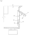
- FIG. 1 is a side sectional view illustrating a structure of a dishwasher according to an embodiment of the present disclosure.
- a dishwasher 10 to which a power cord 30 is coupled includes a housing 11 which forms an exterior, a tub 12 which is protected by the housing 11 and at which a tableware cleaning tub is formed, and a door 13 which is formed at the front of the tub 12 and configured to open/close the tableware cleaning tub.
- the dishwasher 10 includes a sump 14 which is formed at a central portion of the lower surface of the tub 12and at where a cleaning water is stored, a cleaning pump 15 which is connected to the sump 14 and configured to pump the cleaning water stored at the sump 14, and a motor 16 which is disposed at the rear of the cleaning pump 15 and configured to drive the cleaning pump 15.
- the dishwasher 10 includes a water guide 17 which becomes a moving path for the cleaning water which is pumped at the cleaning pump 15, a lower portion nozzle 18 which is formed at the lower portion of the cleaning tub and configured to inject the cleaning water toward an upper direction, and an upper portion nozzle 19 which is split from one point of the water guide 17 and positioned at about a central portion at the inside of the tub 12.
- a top nozzle 20 is equipped at a ceiling portion of the tub 12 to inject the cleaning water in a perpendicular direction toward a bottom.
- An upper rack 21 is installed at the upper side portion of the upper nozzle 19 and a lower rack 22 is installed between the upper nozzle 19 and the lower nozzle 20.
- a base 23 is installed at a lower side of the tub 12, and the power cord 30 is installed at one side of the housing body 40 (refer to FIG. 2 ) which is one portion of the base 23.
- FIG. 2 is a view illustrating a coupling structure of a power cord and a dishwasher in accordance with the embodiment of the present disclosure
- FIG. 3 is an exploded view illustrating a disassembled state of a power cord and a dishwasher in accordance with the embodiment of the present disclosure.
- the power cord 30 is coupled to the housing body 40 which is one side surface of the housing 11 of the dishwasher 10.
- the housing body 40 is provided at one surface with a power cord insertion hole 43 into which the power cord 30 is inserted.
- an open/close unit 41 which is configured to open/close the power cord insertion hole 43 is rotatably connected to the housing body 40.
- each of the three sides of the open/close unit 41 is incised, and the open/close unit 41 is configured not to be completely separated from the housing body 40.
- the open/close unit 41 includes a first accommodation groove 44 which is concavely carved for accommodating a portion of the power cord 30.
- the housing body 40 includes a second accommodation groove 46 which is concavely carved and is formed in a way that the first accommodation groove 44 and the second accommodation groove 46 face each other when the open/close unit 41 closes the power cord insertion hole 43.
- the housing body 40 includes a recess 47 which is formed in steps with respect to a side surface of the outer side of the housing 11.
- the recess 47 may be formed around the second accommodation groove 46.
- the recess 47 when the power cord 30 is coupled, has an effect in improving assemblage.
- the second accommodation groove 46 is provided at a lower side with a housing fastening hole 49 into which a fastening member 48 configured to assemble the power cord 30 to the housing body 40 is inserted.
- the housing fastening hole 49 may be formed at an inside of the recess 47.
- the power cord 30 includes a wire unit 33 which connects to an outside power supply source (not shown) and a fixing unit which fixes the power cord 30 to the housing 11.
- the fixing unit fixes the power cord 30 to the housing 11 when the open/close unit 41 closes the power cord insertion hole 43.
- the power cord 30 is coupled to the open/close unit 41 and the housing body 40 by the fixing unit so that the open/close unit 41 is fixed to the housing body 40.
- the fixing unit includes a coupling member 32 and a fixing member 31.
- the coupling member 32 may include a neck part 37 and a head part 36.
- a ferrite core 35 may be equipped at the rear of the coupling member 32 of the power cord 30 to restrain the occurrence of low frequency noise.
- a fuse holder (not shown) may be coupled to the rear of the coupling member 32. The fuse holder (not shown) is configured to protect a fuse (not shown), and a fuse (not shown) short-circuits for a current not to flow when an overvoltage is applied.
- the power cord fastening hole 49 may be provided at the lower side of the fixing member 31 of the power cord 30 such that the fastening member 48 such as a screw is inserted into the power cord fastening hole 49 for the assembly of the power cord 30 and the housing 11.
- the first accommodation groove 44 is coupled to the coupling member 32 in a case when the power cord 30 is being assembled, and the second accommodation groove 46 is equipped for easier assembly of the power cord 30. Therefore, the first accommodation groove 44 of the open/close unit 41 and the second accommodation groove 46 of the housing body 40 face each other in a first direction, and the length of the first accommodation groove 44 toward the first direction may be longer than the length of the second accommodation groove 46 toward the first direction.
- FIG. 4 is a side view illustrating a state of a power side is coupled to a dishwasher in accordance with the embodiment of the present disclosure
- FIG. 5 is a view illustrating a housing body of a dishwasher to which a power cord is coupled in accordance with the embodiment of the present disclosure
- FIG. 6 is a view illustrating an open state of an open/close unit in accordance with the embodiment of the present disclosure
- FIG. 7 is a side view illustrating an open state of an open/close unit in accordance with the embodiment of the present disclosure.
- the open/close unit 41 is rotatable and is lifted toward the upper side of the housing body 40 for coupling of the power cord 30, so that the component having a large volume such as the ferrite core 35 and the fuse holder (not shown) which are attached to the power cord 30 is inserted through the power cord insertion hole 43. After coupling the power cord 30 to the housing body 40, the open/close unit 41 rotates toward the housing body 40 to its original state.
- the open/close unit 41 is integrally formed with the housing body 40, and is manufactured through an injection molding method.
- the housing 11 which includes the housing body 40 includes plastic material.
- the coupling member 32 of the power cord 30 is coupled to the first accommodation groove 44 of the open/close unit 41, and the fixing member 31 is fixed to the housing body 40.
- the coupling member 32 may include the neck part 37 which is inserted into the first accommodation groove 44 of the open/close unit 41, and the head part 36 which is supported by an inner surface of the open/close unit 41 when the neck part 37 is inserted into the first accommodation groove 44.
- the open/close unit 41 closes the power cord insertion hole 43 in a state that the neck part 37 is inserted into the first accommodation groove 44, a portion of the fixing member 31 of the power cord 30 is supported by an outer surface of the open/close unit 41 while another portion of the fixing member 31 is disposed to be supported by an outer surface of the housing body 40.
- the other portion of the fixing unit 31 supported by the outer surface of the housing body 40 is coupled to the recess 47 formed at the housing body 40, so that the power cord 30 may be stably assembled to the housing 11.
- the housing fastening hole 49 provided at the lower side of the second accommodation groove 46 of the housing body 40 is disposed to overlap a power cord fastening hole 34 provided at the fixing member 31 of the power cord 30. Therefore, the fastening member 48 is inserted into the housing fastening hole 49 and the power cord fastening hole 34, thereby coupling the housing 11 to the power cord 30.
- the fastening member 48 such as a screw into the housing fastening hole 49 and into the power cord fastening hole 34, one portion of the fixing member 31 of the power cord 30 is coupled to the housing body 40, thereby improving the coupling strength of the power cord 30 and the housing 11.
- the fixing member 31, as illustrated on FIG. 4 may be formed in a rectangular shape, and also in a circular shape as well as in other polygonal shapes.
- the power cord 30 is inserted into the power cord insertion hole 43 through the first accommodation groove 44 and the second accommodation groove 46. Therefore, each of the first accommodation groove 44 and the second accommodation groove 46 is configured to have a shape corresponding to the coupling member 32, and the shape of the first accommodation groove 44 and the second accommodation groove 46 is not limited to a rectangular form as illustrated on FIG. 5 ,.
- the power cord 30 is coupled to the housing 11 of the dishwasher 10 through the power cord insertion hole 43.
- the open/close unit 41 which is equipped at the housing body 40 is lifted and the coupling member 32 of the power cord 30 is inserted into the power cord insertion hole 43. If the neck part 37 is coupled to the first accommodation groove 44 equipped at the open/close unit 41, the head part 36 is supported by the inner surface of the open/close unit 41.
- the power cord 30 is moved toward a bottom direction such that the open/close unit 41 is closed.
- the coupling member 32 and the open/close unit 41 may be moved easily through the second accommodation groove 26 equipped at the housing body 40.
- the housing fastening hole 49 is fixed to the power cord fastening hole 34 by using the fastening member 48 such as a screw.
- the first accommodation groove 44 and the second accommodation groove 46 which are respectively formed at a portion of the open/close unit 41 and the housing body 40, are closed by the fixing member 31 of the power cord 30, thereby preventing a foreign substance such as dust or a insect from entering and influencing a product.
- the open/close unit 42 equipped at the housing body 40 may be lifted, and therefore, coupling the power cord 30 to the inner side of the housing 11 is convenient. That is, there is no need to change the size of the power cord insertion hole 43 according to the size of the component connected to the rear of the coupling member 32 of the power cord 30 when the power cord 30 is assembled to the housing 11.
- FIG. 8 is an exploded view illustrating a disassembled state of a dishwasher and a power cord
- the power cord insertion hole 43 which is configured for the power cord 30 to be coupled at one surface of the housing body 40, that is, a portion of the housing of the dishwasher 10, is provided.
- An open/close unit 51 is rotatably connected to the housing body 40, and three sides of the open/close unit 41 are incised.
- the open/close unit 41 is detachably coupled to the housing body 40.
- the open/close unit 51 includes a first accommodation groove 54 to accommodate a portion of the power cord 30.
- a hinge 60 equipped at the open/close unit 41 is engaged to a hinge coupling hole 61equipped at the housing body 40 so that the open/close unit 40 may be detachably coupled to the housing body 40.
- the open/close unit 41 may rotate easily at the housing body 40 through the hinge coupling.
- the housing body 40 includes a recess 57 which is formed in steps at the outer surface of the housing 11.
- the recess 57 is a portion where a portion of the fixing member 31 of the power cord 30 is coupled, and the shape of the recess 57 is formed to correspond to the shape of the fixing member 31.
- the housing body 40 is provided at a lower side of with a housing fastening hole 59 to which a fastening member (not shown) is assembled such that the power cord 30 is coupled to the housing body 40.
- the housing fastening hole 59 may be equipped inside the recess 57.
- the power cord 30, as described above, includes a fixing unit and the wire unit 33.
- the fixing unit includes the coupling member 32 which is coupled to the first accommodation groove 44 of the open/close unit 41 and the fixing member 31 which is fixed to the housing body 40.
- the coupling member 32 includes the neck part 37 which is inserted into the first accommodation groove 44 and the head part 26 which is supported by the inner surface of the open/close unit 41 when the neck part 37 is inserted into the first accommodation groove 44.
- the power cord fastening hole 34 into which the fastening member (not shown) is inserted may be provided at a lower side of the fixing member 31.
- a portion of the fixing member 31 of the power cord 30 is supported by the outer surface of the open/close unit 41, and another portion of the fixing member 31 is supported by the housing body 40. In particular, another portion of the fixing member 31 may be supported by the recess 57.
- the power cord fastening hole 27 and the housing fastening hole 59 are equipped in an overlapping manner.
- the fastening member (not shown) is inserted through the power cord fastening hole 34 and the housing fastening hole 59, and fixes the housing 11 of the dishwasher 10 to the power cord 30.
Landscapes
- Engineering & Computer Science (AREA)
- Architecture (AREA)
- Civil Engineering (AREA)
- Structural Engineering (AREA)
- Microelectronics & Electronic Packaging (AREA)
- Textile Engineering (AREA)
- Insertion, Bundling And Securing Of Wires For Electric Apparatuses (AREA)
- Main Body Construction Of Washing Machines And Laundry Dryers (AREA)
- Washing And Drying Of Tableware (AREA)
Applications Claiming Priority (1)
| Application Number | Priority Date | Filing Date | Title |
|---|---|---|---|
| KR1020110080877A KR101844754B1 (ko) | 2011-08-12 | 2011-08-12 | 식기세척기 및 가전기기 |
Publications (3)
| Publication Number | Publication Date |
|---|---|
| EP2556783A2 true EP2556783A2 (fr) | 2013-02-13 |
| EP2556783A3 EP2556783A3 (fr) | 2016-01-20 |
| EP2556783B1 EP2556783B1 (fr) | 2017-10-11 |
Family
ID=46758617
Family Applications (1)
| Application Number | Title | Priority Date | Filing Date |
|---|---|---|---|
| EP12179512.4A Not-in-force EP2556783B1 (fr) | 2011-08-12 | 2012-08-07 | Lave-vaisselle et appareil électroménager |
Country Status (3)
| Country | Link |
|---|---|
| EP (1) | EP2556783B1 (fr) |
| KR (1) | KR101844754B1 (fr) |
| CN (1) | CN102949163B (fr) |
Cited By (7)
| Publication number | Priority date | Publication date | Assignee | Title |
|---|---|---|---|---|
| CN103277893A (zh) * | 2013-04-17 | 2013-09-04 | 浙江长兴奥利尔家用电器有限公司 | 热水器走线槽 |
| WO2017102248A1 (fr) * | 2015-12-18 | 2017-06-22 | BSH Hausgeräte GmbH | Appareil électroménager à élément protecteur de câble |
| EP3242540A1 (fr) * | 2016-05-06 | 2017-11-08 | Mahle International GmbH | Système de boîtier |
| IT201800000353A1 (it) * | 2018-01-03 | 2019-07-03 | B D G El Srl | Dispositivo per il bloccaggio di cavi |
| CN113215786A (zh) * | 2020-01-21 | 2021-08-06 | 重庆海尔洗衣机有限公司 | 一种洗衣机电源线连接结构及具有该结构的洗衣机 |
| JP2023027447A (ja) * | 2021-08-17 | 2023-03-02 | キヤノン株式会社 | 画像形成装置 |
| EP4394102A1 (fr) * | 2022-12-30 | 2024-07-03 | Arçelik Anonim Sirketi | Appareil électroménager comprenant un support de câble |
Families Citing this family (3)
| Publication number | Priority date | Publication date | Assignee | Title |
|---|---|---|---|---|
| CN105977721B (zh) * | 2016-06-23 | 2018-09-25 | 常州格力博有限公司 | 工作器具外部电源线固定装置 |
| US11901712B1 (en) | 2023-04-13 | 2024-02-13 | Whirlpool Corporation | Panel mounted power-cable system for an appliance |
| US12489285B2 (en) * | 2023-04-13 | 2025-12-02 | Whirlpool Corporation | Panel mounted power-cable system for an appliance |
Family Cites Families (7)
| Publication number | Priority date | Publication date | Assignee | Title |
|---|---|---|---|---|
| DE19536155A1 (de) * | 1995-09-29 | 1997-04-03 | Wuerth Elektronik Gmbh & Co Kg | Einrichtung zum Absorbieren des elektrischen Rauschens |
| ITPN20020015U1 (it) * | 2002-03-13 | 2003-09-15 | Electrolux Home Products Corpo | Elettrodomestico con dispositivo perfezionato di inserimento del cavodi alimentazione. |
| US20050120586A1 (en) * | 2003-12-06 | 2005-06-09 | Hwang Sung G. | Dryer |
| DE112005001546B4 (de) * | 2004-12-08 | 2013-03-14 | Lg Electronics Inc. | Wäschebearbeitungsgerät |
| TR200702331A2 (tr) * | 2007-04-06 | 2008-11-21 | Vestel Beyaz E�Ya Sanay� Ve T�Caret Anon�M ��Rket�@ | Yıkama makinaları için bağlantı kapağı |
| DE102008020888A1 (de) * | 2008-04-25 | 2009-10-29 | BSH Bosch und Siemens Hausgeräte GmbH | Geschirrspülmaschine |
| ITTO20090981A1 (it) * | 2009-12-14 | 2011-06-15 | Bitron Spa | Accessorio integrato per l'alimentazione di una macchina lavastoviglie o lavabiancheria |
-
2011
- 2011-08-12 KR KR1020110080877A patent/KR101844754B1/ko not_active Expired - Fee Related
-
2012
- 2012-08-07 EP EP12179512.4A patent/EP2556783B1/fr not_active Not-in-force
- 2012-08-10 CN CN201210284897.6A patent/CN102949163B/zh not_active Expired - Fee Related
Non-Patent Citations (1)
| Title |
|---|
| None |
Cited By (8)
| Publication number | Priority date | Publication date | Assignee | Title |
|---|---|---|---|---|
| CN103277893A (zh) * | 2013-04-17 | 2013-09-04 | 浙江长兴奥利尔家用电器有限公司 | 热水器走线槽 |
| WO2017102248A1 (fr) * | 2015-12-18 | 2017-06-22 | BSH Hausgeräte GmbH | Appareil électroménager à élément protecteur de câble |
| EP3242540A1 (fr) * | 2016-05-06 | 2017-11-08 | Mahle International GmbH | Système de boîtier |
| IT201800000353A1 (it) * | 2018-01-03 | 2019-07-03 | B D G El Srl | Dispositivo per il bloccaggio di cavi |
| EP3509175A1 (fr) * | 2018-01-03 | 2019-07-10 | B.D.G. el S.r.l. | Dispositif de verrouillage pour un câble |
| CN113215786A (zh) * | 2020-01-21 | 2021-08-06 | 重庆海尔洗衣机有限公司 | 一种洗衣机电源线连接结构及具有该结构的洗衣机 |
| JP2023027447A (ja) * | 2021-08-17 | 2023-03-02 | キヤノン株式会社 | 画像形成装置 |
| EP4394102A1 (fr) * | 2022-12-30 | 2024-07-03 | Arçelik Anonim Sirketi | Appareil électroménager comprenant un support de câble |
Also Published As
| Publication number | Publication date |
|---|---|
| KR20130018045A (ko) | 2013-02-20 |
| EP2556783B1 (fr) | 2017-10-11 |
| CN102949163B (zh) | 2016-12-21 |
| KR101844754B1 (ko) | 2018-04-03 |
| CN102949163A (zh) | 2013-03-06 |
| EP2556783A3 (fr) | 2016-01-20 |
Similar Documents
| Publication | Publication Date | Title |
|---|---|---|
| EP2556783B1 (fr) | Lave-vaisselle et appareil électroménager | |
| KR101880083B1 (ko) | 세탁기 | |
| KR101595680B1 (ko) | 와이어커버가 구비된 커넥터 | |
| US8610527B2 (en) | Field coil assembly of electromagnetic clutch for a compressor | |
| CN101626718A (zh) | 具有可接近控制单元的洗碗机和相关方法 | |
| US20160017530A1 (en) | Washing machine | |
| CN118056043A (zh) | 衣物处理装置 | |
| JP6454126B2 (ja) | 空気調和機の室外機 | |
| EP4206592B1 (fr) | Réfrigérateur et appareil ménager | |
| EP2666731A2 (fr) | Ensemble poignée pour récipient étanche à l'air | |
| CN108625670B (zh) | 一种把手安装结构及具有其的家用电器 | |
| KR101725092B1 (ko) | 팬 모터 | |
| KR102878527B1 (ko) | 세탁기 | |
| CN108901311A (zh) | 一种打草头、其组装方法及打草机 | |
| CN204024247U (zh) | 用于冷柜的锁和具有其的冷柜 | |
| JP2008006048A (ja) | 洗濯機 | |
| CN204683525U (zh) | 面板与外门的装配结构和洗碗机 | |
| KR101610132B1 (ko) | 모터용 로터의 구조 | |
| KR20110119465A (ko) | 가구용 경첩 | |
| KR20120092898A (ko) | 외전형 모터의 접지장치 | |
| KR102713776B1 (ko) | 의류처리장치 | |
| KR20150011043A (ko) | 세탁기 | |
| KR20060085801A (ko) | 세탁기의 파워코드 고정장치 | |
| KR20070009346A (ko) | 냉장고용 디스펜서 어셈블리 | |
| KR20150141355A (ko) | 모터용 로터의 구조 |
Legal Events
| Date | Code | Title | Description |
|---|---|---|---|
| PUAI | Public reference made under article 153(3) epc to a published international application that has entered the european phase |
Free format text: ORIGINAL CODE: 0009012 |
|
| AK | Designated contracting states |
Kind code of ref document: A2 Designated state(s): AL AT BE BG CH CY CZ DE DK EE ES FI FR GB GR HR HU IE IS IT LI LT LU LV MC MK MT NL NO PL PT RO RS SE SI SK SM TR |
|
| AX | Request for extension of the european patent |
Extension state: BA ME |
|
| PUAL | Search report despatched |
Free format text: ORIGINAL CODE: 0009013 |
|
| AK | Designated contracting states |
Kind code of ref document: A3 Designated state(s): AL AT BE BG CH CY CZ DE DK EE ES FI FR GB GR HR HU IE IS IT LI LT LU LV MC MK MT NL NO PL PT RO RS SE SI SK SM TR |
|
| AX | Request for extension of the european patent |
Extension state: BA ME |
|
| RIC1 | Information provided on ipc code assigned before grant |
Ipc: A47L 15/42 20060101AFI20151215BHEP Ipc: H02G 3/22 20060101ALN20151215BHEP Ipc: H05K 5/02 20060101ALI20151215BHEP |
|
| 17P | Request for examination filed |
Effective date: 20160720 |
|
| RBV | Designated contracting states (corrected) |
Designated state(s): AL AT BE BG CH CY CZ DE DK EE ES FI FR GB GR HR HU IE IS IT LI LT LU LV MC MK MT NL NO PL PT RO RS SE SI SK SM TR |
|
| GRAP | Despatch of communication of intention to grant a patent |
Free format text: ORIGINAL CODE: EPIDOSNIGR1 |
|
| INTG | Intention to grant announced |
Effective date: 20170420 |
|
| GRAS | Grant fee paid |
Free format text: ORIGINAL CODE: EPIDOSNIGR3 |
|
| GRAA | (expected) grant |
Free format text: ORIGINAL CODE: 0009210 |
|
| AK | Designated contracting states |
Kind code of ref document: B1 Designated state(s): AL AT BE BG CH CY CZ DE DK EE ES FI FR GB GR HR HU IE IS IT LI LT LU LV MC MK MT NL NO PL PT RO RS SE SI SK SM TR |
|
| REG | Reference to a national code |
Ref country code: GB Ref legal event code: FG4D |
|
| REG | Reference to a national code |
Ref country code: CH Ref legal event code: EP |
|
| REG | Reference to a national code |
Ref country code: IE Ref legal event code: FG4D |
|
| REG | Reference to a national code |
Ref country code: AT Ref legal event code: REF Ref document number: 935281 Country of ref document: AT Kind code of ref document: T Effective date: 20171115 |
|
| REG | Reference to a national code |
Ref country code: DE Ref legal event code: R096 Ref document number: 602012038325 Country of ref document: DE |
|
| REG | Reference to a national code |
Ref country code: NL Ref legal event code: MP Effective date: 20171011 |
|
| REG | Reference to a national code |
Ref country code: LT Ref legal event code: MG4D |
|
| REG | Reference to a national code |
Ref country code: AT Ref legal event code: MK05 Ref document number: 935281 Country of ref document: AT Kind code of ref document: T Effective date: 20171011 |
|
| PG25 | Lapsed in a contracting state [announced via postgrant information from national office to epo] |
Ref country code: NL Free format text: LAPSE BECAUSE OF FAILURE TO SUBMIT A TRANSLATION OF THE DESCRIPTION OR TO PAY THE FEE WITHIN THE PRESCRIBED TIME-LIMIT Effective date: 20171011 |
|
| PG25 | Lapsed in a contracting state [announced via postgrant information from national office to epo] |
Ref country code: NO Free format text: LAPSE BECAUSE OF FAILURE TO SUBMIT A TRANSLATION OF THE DESCRIPTION OR TO PAY THE FEE WITHIN THE PRESCRIBED TIME-LIMIT Effective date: 20180111 Ref country code: LT Free format text: LAPSE BECAUSE OF FAILURE TO SUBMIT A TRANSLATION OF THE DESCRIPTION OR TO PAY THE FEE WITHIN THE PRESCRIBED TIME-LIMIT Effective date: 20171011 Ref country code: FI Free format text: LAPSE BECAUSE OF FAILURE TO SUBMIT A TRANSLATION OF THE DESCRIPTION OR TO PAY THE FEE WITHIN THE PRESCRIBED TIME-LIMIT Effective date: 20171011 Ref country code: SE Free format text: LAPSE BECAUSE OF FAILURE TO SUBMIT A TRANSLATION OF THE DESCRIPTION OR TO PAY THE FEE WITHIN THE PRESCRIBED TIME-LIMIT Effective date: 20171011 Ref country code: ES Free format text: LAPSE BECAUSE OF FAILURE TO SUBMIT A TRANSLATION OF THE DESCRIPTION OR TO PAY THE FEE WITHIN THE PRESCRIBED TIME-LIMIT Effective date: 20171011 |
|
| PG25 | Lapsed in a contracting state [announced via postgrant information from national office to epo] |
Ref country code: IS Free format text: LAPSE BECAUSE OF FAILURE TO SUBMIT A TRANSLATION OF THE DESCRIPTION OR TO PAY THE FEE WITHIN THE PRESCRIBED TIME-LIMIT Effective date: 20180211 Ref country code: AT Free format text: LAPSE BECAUSE OF FAILURE TO SUBMIT A TRANSLATION OF THE DESCRIPTION OR TO PAY THE FEE WITHIN THE PRESCRIBED TIME-LIMIT Effective date: 20171011 Ref country code: LV Free format text: LAPSE BECAUSE OF FAILURE TO SUBMIT A TRANSLATION OF THE DESCRIPTION OR TO PAY THE FEE WITHIN THE PRESCRIBED TIME-LIMIT Effective date: 20171011 Ref country code: HR Free format text: LAPSE BECAUSE OF FAILURE TO SUBMIT A TRANSLATION OF THE DESCRIPTION OR TO PAY THE FEE WITHIN THE PRESCRIBED TIME-LIMIT Effective date: 20171011 Ref country code: RS Free format text: LAPSE BECAUSE OF FAILURE TO SUBMIT A TRANSLATION OF THE DESCRIPTION OR TO PAY THE FEE WITHIN THE PRESCRIBED TIME-LIMIT Effective date: 20171011 Ref country code: BG Free format text: LAPSE BECAUSE OF FAILURE TO SUBMIT A TRANSLATION OF THE DESCRIPTION OR TO PAY THE FEE WITHIN THE PRESCRIBED TIME-LIMIT Effective date: 20180111 Ref country code: GR Free format text: LAPSE BECAUSE OF FAILURE TO SUBMIT A TRANSLATION OF THE DESCRIPTION OR TO PAY THE FEE WITHIN THE PRESCRIBED TIME-LIMIT Effective date: 20180112 |
|
| REG | Reference to a national code |
Ref country code: DE Ref legal event code: R097 Ref document number: 602012038325 Country of ref document: DE |
|
| PG25 | Lapsed in a contracting state [announced via postgrant information from national office to epo] |
Ref country code: SK Free format text: LAPSE BECAUSE OF FAILURE TO SUBMIT A TRANSLATION OF THE DESCRIPTION OR TO PAY THE FEE WITHIN THE PRESCRIBED TIME-LIMIT Effective date: 20171011 Ref country code: EE Free format text: LAPSE BECAUSE OF FAILURE TO SUBMIT A TRANSLATION OF THE DESCRIPTION OR TO PAY THE FEE WITHIN THE PRESCRIBED TIME-LIMIT Effective date: 20171011 Ref country code: CZ Free format text: LAPSE BECAUSE OF FAILURE TO SUBMIT A TRANSLATION OF THE DESCRIPTION OR TO PAY THE FEE WITHIN THE PRESCRIBED TIME-LIMIT Effective date: 20171011 Ref country code: DK Free format text: LAPSE BECAUSE OF FAILURE TO SUBMIT A TRANSLATION OF THE DESCRIPTION OR TO PAY THE FEE WITHIN THE PRESCRIBED TIME-LIMIT Effective date: 20171011 |
|
| PLBE | No opposition filed within time limit |
Free format text: ORIGINAL CODE: 0009261 |
|
| STAA | Information on the status of an ep patent application or granted ep patent |
Free format text: STATUS: NO OPPOSITION FILED WITHIN TIME LIMIT |
|
| REG | Reference to a national code |
Ref country code: FR Ref legal event code: PLFP Year of fee payment: 7 |
|
| PG25 | Lapsed in a contracting state [announced via postgrant information from national office to epo] |
Ref country code: SM Free format text: LAPSE BECAUSE OF FAILURE TO SUBMIT A TRANSLATION OF THE DESCRIPTION OR TO PAY THE FEE WITHIN THE PRESCRIBED TIME-LIMIT Effective date: 20171011 Ref country code: IT Free format text: LAPSE BECAUSE OF FAILURE TO SUBMIT A TRANSLATION OF THE DESCRIPTION OR TO PAY THE FEE WITHIN THE PRESCRIBED TIME-LIMIT Effective date: 20171011 Ref country code: PL Free format text: LAPSE BECAUSE OF FAILURE TO SUBMIT A TRANSLATION OF THE DESCRIPTION OR TO PAY THE FEE WITHIN THE PRESCRIBED TIME-LIMIT Effective date: 20171011 Ref country code: RO Free format text: LAPSE BECAUSE OF FAILURE TO SUBMIT A TRANSLATION OF THE DESCRIPTION OR TO PAY THE FEE WITHIN THE PRESCRIBED TIME-LIMIT Effective date: 20171011 |
|
| 26N | No opposition filed |
Effective date: 20180712 |
|
| PG25 | Lapsed in a contracting state [announced via postgrant information from national office to epo] |
Ref country code: SI Free format text: LAPSE BECAUSE OF FAILURE TO SUBMIT A TRANSLATION OF THE DESCRIPTION OR TO PAY THE FEE WITHIN THE PRESCRIBED TIME-LIMIT Effective date: 20171011 |
|
| PG25 | Lapsed in a contracting state [announced via postgrant information from national office to epo] |
Ref country code: MC Free format text: LAPSE BECAUSE OF FAILURE TO SUBMIT A TRANSLATION OF THE DESCRIPTION OR TO PAY THE FEE WITHIN THE PRESCRIBED TIME-LIMIT Effective date: 20171011 |
|
| REG | Reference to a national code |
Ref country code: CH Ref legal event code: PL |
|
| PG25 | Lapsed in a contracting state [announced via postgrant information from national office to epo] |
Ref country code: CH Free format text: LAPSE BECAUSE OF NON-PAYMENT OF DUE FEES Effective date: 20180831 Ref country code: LI Free format text: LAPSE BECAUSE OF NON-PAYMENT OF DUE FEES Effective date: 20180831 Ref country code: LU Free format text: LAPSE BECAUSE OF NON-PAYMENT OF DUE FEES Effective date: 20180807 |
|
| REG | Reference to a national code |
Ref country code: BE Ref legal event code: MM Effective date: 20180831 |
|
| REG | Reference to a national code |
Ref country code: IE Ref legal event code: MM4A |
|
| PG25 | Lapsed in a contracting state [announced via postgrant information from national office to epo] |
Ref country code: IE Free format text: LAPSE BECAUSE OF NON-PAYMENT OF DUE FEES Effective date: 20180807 |
|
| PG25 | Lapsed in a contracting state [announced via postgrant information from national office to epo] |
Ref country code: BE Free format text: LAPSE BECAUSE OF NON-PAYMENT OF DUE FEES Effective date: 20180831 |
|
| PG25 | Lapsed in a contracting state [announced via postgrant information from national office to epo] |
Ref country code: MT Free format text: LAPSE BECAUSE OF NON-PAYMENT OF DUE FEES Effective date: 20180807 |
|
| PG25 | Lapsed in a contracting state [announced via postgrant information from national office to epo] |
Ref country code: TR Free format text: LAPSE BECAUSE OF FAILURE TO SUBMIT A TRANSLATION OF THE DESCRIPTION OR TO PAY THE FEE WITHIN THE PRESCRIBED TIME-LIMIT Effective date: 20171011 |
|
| PG25 | Lapsed in a contracting state [announced via postgrant information from national office to epo] |
Ref country code: HU Free format text: LAPSE BECAUSE OF FAILURE TO SUBMIT A TRANSLATION OF THE DESCRIPTION OR TO PAY THE FEE WITHIN THE PRESCRIBED TIME-LIMIT; INVALID AB INITIO Effective date: 20120807 Ref country code: PT Free format text: LAPSE BECAUSE OF FAILURE TO SUBMIT A TRANSLATION OF THE DESCRIPTION OR TO PAY THE FEE WITHIN THE PRESCRIBED TIME-LIMIT Effective date: 20171011 |
|
| PG25 | Lapsed in a contracting state [announced via postgrant information from national office to epo] |
Ref country code: CY Free format text: LAPSE BECAUSE OF FAILURE TO SUBMIT A TRANSLATION OF THE DESCRIPTION OR TO PAY THE FEE WITHIN THE PRESCRIBED TIME-LIMIT Effective date: 20171011 Ref country code: MK Free format text: LAPSE BECAUSE OF NON-PAYMENT OF DUE FEES Effective date: 20171011 |
|
| PG25 | Lapsed in a contracting state [announced via postgrant information from national office to epo] |
Ref country code: AL Free format text: LAPSE BECAUSE OF FAILURE TO SUBMIT A TRANSLATION OF THE DESCRIPTION OR TO PAY THE FEE WITHIN THE PRESCRIBED TIME-LIMIT Effective date: 20171011 |
|
| PGFP | Annual fee paid to national office [announced via postgrant information from national office to epo] |
Ref country code: FR Payment date: 20210726 Year of fee payment: 10 |
|
| PGFP | Annual fee paid to national office [announced via postgrant information from national office to epo] |
Ref country code: GB Payment date: 20210726 Year of fee payment: 10 Ref country code: DE Payment date: 20210720 Year of fee payment: 10 |
|
| REG | Reference to a national code |
Ref country code: DE Ref legal event code: R119 Ref document number: 602012038325 Country of ref document: DE |
|
| GBPC | Gb: european patent ceased through non-payment of renewal fee |
Effective date: 20220807 |
|
| PG25 | Lapsed in a contracting state [announced via postgrant information from national office to epo] |
Ref country code: FR Free format text: LAPSE BECAUSE OF NON-PAYMENT OF DUE FEES Effective date: 20220831 Ref country code: DE Free format text: LAPSE BECAUSE OF NON-PAYMENT OF DUE FEES Effective date: 20230301 |
|
| PG25 | Lapsed in a contracting state [announced via postgrant information from national office to epo] |
Ref country code: GB Free format text: LAPSE BECAUSE OF NON-PAYMENT OF DUE FEES Effective date: 20220807 |