EP2556790A1 - Dispositif endoscopique - Google Patents
Dispositif endoscopique Download PDFInfo
- Publication number
- EP2556790A1 EP2556790A1 EP20120178513 EP12178513A EP2556790A1 EP 2556790 A1 EP2556790 A1 EP 2556790A1 EP 20120178513 EP20120178513 EP 20120178513 EP 12178513 A EP12178513 A EP 12178513A EP 2556790 A1 EP2556790 A1 EP 2556790A1
- Authority
- EP
- European Patent Office
- Prior art keywords
- light
- intensity ratio
- module
- light intensity
- illuminating
- Prior art date
- Legal status (The legal status is an assumption and is not a legal conclusion. Google has not performed a legal analysis and makes no representation as to the accuracy of the status listed.)
- Withdrawn
Links
- 238000003384 imaging method Methods 0.000 claims abstract description 52
- 238000001228 spectrum Methods 0.000 claims abstract description 10
- 239000008280 blood Substances 0.000 claims description 19
- 210000004369 blood Anatomy 0.000 claims description 19
- 210000004400 mucous membrane Anatomy 0.000 claims description 17
- 238000012937 correction Methods 0.000 claims description 15
- 238000012545 processing Methods 0.000 claims description 13
- 239000011159 matrix material Substances 0.000 claims description 10
- 239000000284 extract Substances 0.000 claims description 8
- 230000009466 transformation Effects 0.000 claims description 6
- 238000006243 chemical reaction Methods 0.000 claims description 5
- 238000000034 method Methods 0.000 description 10
- 238000012327 Endoscopic diagnosis Methods 0.000 description 8
- 238000005286 illumination Methods 0.000 description 8
- 230000003902 lesion Effects 0.000 description 7
- 230000003595 spectral effect Effects 0.000 description 7
- 238000010586 diagram Methods 0.000 description 6
- 230000003287 optical effect Effects 0.000 description 6
- 210000004204 blood vessel Anatomy 0.000 description 5
- 239000013307 optical fiber Substances 0.000 description 5
- 239000004065 semiconductor Substances 0.000 description 5
- 238000012790 confirmation Methods 0.000 description 3
- 238000003745 diagnosis Methods 0.000 description 3
- 230000001678 irradiating effect Effects 0.000 description 3
- 230000000295 complement effect Effects 0.000 description 2
- 238000001839 endoscopy Methods 0.000 description 2
- 238000009877 rendering Methods 0.000 description 2
- 239000000126 substance Substances 0.000 description 2
- 238000010521 absorption reaction Methods 0.000 description 1
- 239000003086 colorant Substances 0.000 description 1
- 238000013461 design Methods 0.000 description 1
- 238000001514 detection method Methods 0.000 description 1
- 238000005516 engineering process Methods 0.000 description 1
- 230000006870 function Effects 0.000 description 1
- 229910052736 halogen Inorganic materials 0.000 description 1
- 150000002367 halogens Chemical class 0.000 description 1
- 229910044991 metal oxide Inorganic materials 0.000 description 1
- 150000004706 metal oxides Chemical class 0.000 description 1
- XLYOFNOQVPJJNP-UHFFFAOYSA-N water Substances O XLYOFNOQVPJJNP-UHFFFAOYSA-N 0.000 description 1
- 229910052724 xenon Inorganic materials 0.000 description 1
- FHNFHKCVQCLJFQ-UHFFFAOYSA-N xenon atom Chemical compound [Xe] FHNFHKCVQCLJFQ-UHFFFAOYSA-N 0.000 description 1
Images




Classifications
-
- A—HUMAN NECESSITIES
- A61—MEDICAL OR VETERINARY SCIENCE; HYGIENE
- A61B—DIAGNOSIS; SURGERY; IDENTIFICATION
- A61B1/00—Instruments for performing medical examinations of the interior of cavities or tubes of the body by visual or photographical inspection, e.g. endoscopes; Illuminating arrangements therefor
- A61B1/06—Instruments for performing medical examinations of the interior of cavities or tubes of the body by visual or photographical inspection, e.g. endoscopes; Illuminating arrangements therefor with illuminating arrangements
- A61B1/0638—Instruments for performing medical examinations of the interior of cavities or tubes of the body by visual or photographical inspection, e.g. endoscopes; Illuminating arrangements therefor with illuminating arrangements providing two or more wavelengths
-
- A—HUMAN NECESSITIES
- A61—MEDICAL OR VETERINARY SCIENCE; HYGIENE
- A61B—DIAGNOSIS; SURGERY; IDENTIFICATION
- A61B1/00—Instruments for performing medical examinations of the interior of cavities or tubes of the body by visual or photographical inspection, e.g. endoscopes; Illuminating arrangements therefor
- A61B1/00002—Operational features of endoscopes
- A61B1/00004—Operational features of endoscopes characterised by electronic signal processing
- A61B1/00006—Operational features of endoscopes characterised by electronic signal processing of control signals
-
- A—HUMAN NECESSITIES
- A61—MEDICAL OR VETERINARY SCIENCE; HYGIENE
- A61B—DIAGNOSIS; SURGERY; IDENTIFICATION
- A61B1/00—Instruments for performing medical examinations of the interior of cavities or tubes of the body by visual or photographical inspection, e.g. endoscopes; Illuminating arrangements therefor
- A61B1/00002—Operational features of endoscopes
- A61B1/00004—Operational features of endoscopes characterised by electronic signal processing
- A61B1/00009—Operational features of endoscopes characterised by electronic signal processing of image signals during a use of endoscope
- A61B1/000095—Operational features of endoscopes characterised by electronic signal processing of image signals during a use of endoscope for image enhancement
-
- A—HUMAN NECESSITIES
- A61—MEDICAL OR VETERINARY SCIENCE; HYGIENE
- A61B—DIAGNOSIS; SURGERY; IDENTIFICATION
- A61B1/00—Instruments for performing medical examinations of the interior of cavities or tubes of the body by visual or photographical inspection, e.g. endoscopes; Illuminating arrangements therefor
- A61B1/00002—Operational features of endoscopes
- A61B1/00043—Operational features of endoscopes provided with output arrangements
- A61B1/00045—Display arrangement
-
- A—HUMAN NECESSITIES
- A61—MEDICAL OR VETERINARY SCIENCE; HYGIENE
- A61B—DIAGNOSIS; SURGERY; IDENTIFICATION
- A61B1/00—Instruments for performing medical examinations of the interior of cavities or tubes of the body by visual or photographical inspection, e.g. endoscopes; Illuminating arrangements therefor
- A61B1/06—Instruments for performing medical examinations of the interior of cavities or tubes of the body by visual or photographical inspection, e.g. endoscopes; Illuminating arrangements therefor with illuminating arrangements
- A61B1/0653—Instruments for performing medical examinations of the interior of cavities or tubes of the body by visual or photographical inspection, e.g. endoscopes; Illuminating arrangements therefor with illuminating arrangements with wavelength conversion
-
- A—HUMAN NECESSITIES
- A61—MEDICAL OR VETERINARY SCIENCE; HYGIENE
- A61B—DIAGNOSIS; SURGERY; IDENTIFICATION
- A61B1/00—Instruments for performing medical examinations of the interior of cavities or tubes of the body by visual or photographical inspection, e.g. endoscopes; Illuminating arrangements therefor
- A61B1/06—Instruments for performing medical examinations of the interior of cavities or tubes of the body by visual or photographical inspection, e.g. endoscopes; Illuminating arrangements therefor with illuminating arrangements
- A61B1/0655—Control therefor
-
- A—HUMAN NECESSITIES
- A61—MEDICAL OR VETERINARY SCIENCE; HYGIENE
- A61B—DIAGNOSIS; SURGERY; IDENTIFICATION
- A61B1/00—Instruments for performing medical examinations of the interior of cavities or tubes of the body by visual or photographical inspection, e.g. endoscopes; Illuminating arrangements therefor
- A61B1/06—Instruments for performing medical examinations of the interior of cavities or tubes of the body by visual or photographical inspection, e.g. endoscopes; Illuminating arrangements therefor with illuminating arrangements
- A61B1/0661—Endoscope light sources
-
- A—HUMAN NECESSITIES
- A61—MEDICAL OR VETERINARY SCIENCE; HYGIENE
- A61B—DIAGNOSIS; SURGERY; IDENTIFICATION
- A61B5/00—Measuring for diagnostic purposes; Identification of persons
- A61B5/48—Other medical applications
- A61B5/4887—Locating particular structures in or on the body
- A61B5/489—Blood vessels
-
- A—HUMAN NECESSITIES
- A61—MEDICAL OR VETERINARY SCIENCE; HYGIENE
- A61B—DIAGNOSIS; SURGERY; IDENTIFICATION
- A61B5/00—Measuring for diagnostic purposes; Identification of persons
- A61B5/72—Signal processing specially adapted for physiological signals or for diagnostic purposes
- A61B5/7235—Details of waveform analysis
- A61B5/7253—Details of waveform analysis characterised by using transforms
- A61B5/7257—Details of waveform analysis characterised by using transforms using Fourier transforms
-
- A—HUMAN NECESSITIES
- A61—MEDICAL OR VETERINARY SCIENCE; HYGIENE
- A61B—DIAGNOSIS; SURGERY; IDENTIFICATION
- A61B1/00—Instruments for performing medical examinations of the interior of cavities or tubes of the body by visual or photographical inspection, e.g. endoscopes; Illuminating arrangements therefor
- A61B1/04—Instruments for performing medical examinations of the interior of cavities or tubes of the body by visual or photographical inspection, e.g. endoscopes; Illuminating arrangements therefor combined with photographic or television appliances
- A61B1/044—Instruments for performing medical examinations of the interior of cavities or tubes of the body by visual or photographical inspection, e.g. endoscopes; Illuminating arrangements therefor combined with photographic or television appliances for absorption imaging
-
- A—HUMAN NECESSITIES
- A61—MEDICAL OR VETERINARY SCIENCE; HYGIENE
- A61B—DIAGNOSIS; SURGERY; IDENTIFICATION
- A61B1/00—Instruments for performing medical examinations of the interior of cavities or tubes of the body by visual or photographical inspection, e.g. endoscopes; Illuminating arrangements therefor
- A61B1/06—Instruments for performing medical examinations of the interior of cavities or tubes of the body by visual or photographical inspection, e.g. endoscopes; Illuminating arrangements therefor with illuminating arrangements
- A61B1/063—Instruments for performing medical examinations of the interior of cavities or tubes of the body by visual or photographical inspection, e.g. endoscopes; Illuminating arrangements therefor with illuminating arrangements for monochromatic or narrow-band illumination
Definitions
- the present invention relates to an endoscopic device.
- An endoscopic device that is used in the medical field performs a normal observation that observes a subject image almost same as the observation by naked eyes by irradiating white light onto a subject in a biological body as well as a narrow band observation that observes a subject image by irradiating narrow band light having narrower wavelength band than the light irradiated during the normal observation.
- the narrow band observation observes the blood capillary or a micro pattern of a superficial portion of the mucous membrane in the biological body with a good contrast and helps for an early detection of lesions.
- the endoscopic device that is available for the narrow band observation preferably changes the light intensities of the light emitted from the white light and the narrow band light depending on the observation scene.
- the endoscopic device available for the narrow band observation increases the light intensity of the narrow band light in order to easily observe the blood capillary of the superficial portion of the mucous membrane at the time of near view imaging and increases the light intensity of the white light at the time of distant view imaging to resolve the insufficient amount of irradiated light. By doing this, an observation image suitable for endoscopic diagnosis may be obtained.
- An endoscopic device that performs the above-mentioned narrow band observation is disclosed in JP-A-2011-10998 .
- the white light and the narrow band light are irradiated onto the subject while appropriately changing the emitted light intensity ratio of the white light and the narrow band light, the color shade of the illuminating light is changed. As a result, the color tone of the observation image is changed. If the color tone of the observation image is changed, an operator may be bothered by a feeling of strangeness, which may influence an accurate endoscopic diagnosis. Further, if a predetermined image processing is performed to the observation image, an intended image may not be obtained.
- an endoscopic device can correct the observation image so that the color tone of the observation image is not changed even though the light intensity ratio of the illuminating light is changed when each illuminating light is emitted from a plurality of light sources that emit light having different spectrums, thereby performing accurate endoscopic diagnosis by observing using illuminating light with an optimal light intensity ratio.
- an endoscopic device that irradiates a plurality of illuminating light having different spectrums from each other onto a subject at a front edge of an endoscope inserting module and captures the subject to obtain an observation image.
- the endoscopic device includes an illuminating module, an imaging module, a light intensity ratio control module, and a color tone correcting module.
- the illuminating module generates the plurality of illuminating light.
- the imaging module captures the subject and output an image signal of the observation image.
- the light intensity ratio control module controls the illuminating module to irradiate the plurality of illuminating light onto the subject with a set light intensity ratio by setting the light intensity ratio of the plurality of illuminating light for every observation image.
- the color tone correcting module corrects the color tone of the image signal so as to obtain the observation image with substantially the same color tone even though the light intensity ratio is changed.
- the endoscopic device may correct the observation image such that the color tone of the observation image is not changed even though the light intensity ratio of the illuminating light is changed. Therefore, the observation is performed with the illuminating light at an optimal light intensity ratio, so that it is possible to easily diagnose an object to be observed and accurately perform diagnosis using the endoscope.
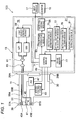
- FIG. 1 is a block diagram of the configuration of an endoscopic device according to an exemplary embodiment of the present invention
- FIG. 2 is an external view illustrating a specific configuration example of the endoscopic device.
- An endoscopic device 100 includes an endoscope 11, a control device 13, a monitor 15, and an input module 17 such as a keyboard or a mouse that inputs information to the control device 13.
- the control device 13 is constituted by a light source device 19 that outputs illuminating light and a processor 21 that performs signal processing of an observation image.
- the endoscope 11 as shown in FIG. 2 , includes a main body operating module 23, an inserting module 25 that is coupled to the main body operating module 23 to be inserted into the subject (body cavity), and a universal cord 27 that is connected to the main body operating module 23.
- the front edge of the universal cord 27 is provided with a light guide (LG) connector 29B that is connected to the light source device 19 and a video connector 29A that is connected to the processor 21.
- LG light guide
- buttons 31 including a button for suctioning, air supplying, and water supplying at the front edge side of the inserting module 25, a shutter button at the time of imaging, a mode switching button that switches an observation mode, and a confirmation button 30 for confirming a lesion area at the time of endoscopic diagnosis, which will be described below, are provided together in the main body operating module 23 of the endoscope 11.
- a pair of angle knobs 33 is provided in the main body operating module 23.
- the inserting module 25 is constituted by a flexible part 35, a curvature part 37, and a front edge part (an endoscope front edge part) 39 in order from the main body operating module 23 side.
- the curvature part 37 is remotely curved by rotating the angle knob 33 of the main body operating module 23, which allows the front edge part 39 to be oriented in a desired direction.
- an observation window 41 of an imaging optical system and illumination windows 43A, 43B of an illuminating optical system are arranged.
- Each of the illumination windows 43A, 43B emits illuminating light onto the subject.
- the reflected light from the subject is detected (captured) by an image pickup device 45 through the observation window 41.
- An image signal output from the image pickup device 45 is digitalized by an analogue/digital (A/D) converting module 47 and then, the image signal is input to the processor 21 through a signal cable 49 to be subjected to an appropriate image processing thereon, and the image signal is displayed on the monitor 15 connected to the processor 21.
- A/D analogue/digital
- the imaging optical system includes the image pickup device 45 such as a charge coupled device (CCD) type image sensor or a complementary metal oxide semiconductor (CMOS) type image sensor and an optical member 51 such as a lens that forms the observation image onto the image pickup device 45.
- the image pickup device 45 may include a color filter of complementary color such as CMY or CMYG in addition to a color filter of RGB primary color.
- An imaging condition of the image pickup device 45 such as a shutter speed or an iris diaphragm is set by an imaging control module 53.
- the illuminating optical system includes the light source device 19, a pair of optical fibers 55A, 55B connected to the light source device 19 through the light guide connector 29B, and wavelength converting members 57A, 57B which are disposed at light emitting ends of the optical fibers 55A, 55B, respectively.
- the light source device 19 includes laser light sources LD1, LD2 which are semiconductor light emitting elements, a light source control module 59 that controls to drive the laser light sources LD1, LD2, a combiner 61 that combines the light emitted from the laser light sources LD1, LD2, and a coupler 63 that divides the light emitted from the combiner 61 into the optical fibers 55A, 55B.
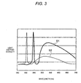
- the laser light source LD1 is a blue light emitting semiconductor laser having a central wavelength of 445 nm and combines the blue laser light and fluorescence obtained by exciting the wavelength converting members 57A, 57B to generate white illuminating light.
- the laser light source LD2 is a violet light emitting semiconductor laser having a central wavelength of 405 nm.
- a broad area type InGaN-based laser diode may be used as the laser light sources. If the central wavelength of the emitted light is in a range between 370 nm and 470 nm, the laser light source LD2 allows good narrow band observation in which the blood capillary or a micro pattern of a superficial portion of the mucous membrane is emphasized.
- a band width of wavelength of each of the laser light sources LD1 and LD2 at half maximum is equal to or less than 60 nm, preferably equal to or less than 40nm, more preferably equal to or less than 20 nm. In view of the light intensity, the band width at half maximum is preferably equal to or less than 10nm.
- the light source control module 59 controls the light intensity of each of the laser light sources LD1, LD2 based on the command of the control module 71 of the processor 21.
- the emitted light passes through the optical fibers 55A, 55B to be guided to the endoscope front edge part 39 and then is irradiated on the wavelength converting members 57A, 57B.
- the light source control module 59 controls the light emitted from the laser light sources LD1, LD2 so as to simultaneously emit light from the illumination windows 43A, 43B with an arbitrary light intensity at an arbitrary timing.
- the wavelength converting members 57A, 57B are configured to include a plurality kinds of fluorescent substances (for example, YAG fluorescence or fluorescence including, for example, BAM (BaMgAl 10 O 37 )) that absorb a part of a blue laser light emitted from the laser light source LD1 and emits green to yellow color light.
- a plurality kinds of fluorescent substances for example, YAG fluorescence or fluorescence including, for example, BAM (BaMgAl 10 O 37 )
- BAM BaMgAl 10 O 37
- the absorption of the fluorescence is low and the wavelength converting efficiency by the wavelength converting members 57A, 57B is low. Therefore, the intensity of the fluorescence generated by the laser light source LD2 is insufficient as compared with the laser light source LD1.
- the light emitted from the laser light source LD2 is mostly narrow band light having a central wavelength of 405 nm, which is substantially shorter than the white light, and having a narrower wavelength band than the white light.
- the laser light emitted from the laser light sources LD1, LD2 are guided to the endoscope front edge part 39 by the optical fibers 55A, 55B so that the white light and violet narrow band light are emitted from both illumination windows 43A, 43B of the endoscope front edge part 39 with an arbitrary light intensity ratio based on the command from the control module 71.
- the laser light from both laser light sources LD1, LD2 is irradiated onto the subject through the same fluorescent substance at the illumination windows 43A, 43B, so that the laser light is irradiated onto the subject so as to be substantially equally spread from the same portion. Therefore, there is no difference in the illumination range by the emitted light or difference in the intensity distribution, which allows obtaining a good observation image.
- control module 71 outputs a control signal to the light source control module 59 and the light source control module 59 outputs a driving signal, which turns ON/OFF the laser light sources LD1, LD2 by the input control signal.
- the laser light sources LD1, LD2 emit light with a light intensity based on the input driving signal. Therefore, the intensity or light intensity ratio (color shade) of the light emitted from the illumination windows 43A, 43B is adjusted. Accordingly, the control module 71 functions as a light intensity control module that changes the light intensity ratio of the white light and the narrow band light of the illuminating light.
- the processor 21 includes the control module 71, a frame memory 73 that stores the picked up image signal, an imaging distance estimating module 75 that estimates an imaging distance to the subject based on the brightness information of the image signal, an optimal light intensity ratio setting module 77 that sets the light intensity ratio suitable for observation, and a setting information storing module 79 that stores various information for setting the optimal light intensity ratio.
- the processor 21 further includes a color tone correcting module 83 that corrects the color tone of the image signal and an image processing module 85.
- the control module 71 sets the light intensity ratio of the light emitted from the laser light sources LD1, LD2 which is optimal for the observation image with respect to the image signal of the observation image including, for example, the lesion area. Therefore, the observation image may be always suitable for the endoscopic diagnosis.
- FIG. 4 illustrates a flowchart of an observation procedure in a body cavity by the endoscopic device 100.
- the operator of the endoscopic device 100 sets the light intensity ratio of the light emitted from the laser light sources LD1, LD2 to a standard light intensity ratio for endoscopy (S1).
- the light intensity ratio may be manually or automatically set, for example, input from the input module 17 connected to the control device 13 or set by referring to the standard light intensity ratio stored in the setting information storing module 79 in advance.
- the operator starts the endoscopy by inserting the endoscope inserting module 25 to which the white light from the front edge is emitted into the subject (S2).
- the control module 71 outputs the observation image of the inside of the subject to the monitor 15 so as to display the observation image on the monitor 15.
- the operator identifies the lesion area from the displayed observation image. If there is a lesion area (S3), the operator presses the confirmation button 30 (see, for example, FIGS. 1 and 2 ) of the main body operating module 23.
- the control module 71 receives a signal that the confirmation button 30 is pressed and estimates the imaging distance to the subject based on the information of AE value which is an imaging condition of the observation image and the information of the illuminating light intensity that is set by the light source control module 59 (S4).
- AE value which is an imaging condition of the observation image
- the information of the illuminating light intensity that is set by the light source control module 59 (S4).
- the AE value and the distance table information which indicates the relationship between the estimated distance L and the reflection light intensity defined by the illuminating light intensity, are prepared in advance as shown in FIG. 5 , and then the imaging distance is estimated by referring to the distance table information.
- the distance table information is prepared for every AE value (for example, shutter speed, iris diaphragm, and brightness) at the time of imaging and imaging condition of the illuminating light intensity, and the distance table information is stored in the setting information storing module 79.
- the control module 71 selectively refers to the distance table information corresponding to the imaging condition of the observation image to estimate the imaging distance L.
- the control module 71 calculates the optimal light intensity ratio [LD1 ( ⁇ 445 ): LD 2 ( ⁇ 405 )] for the estimated imaging distance L.
- the distance and light intensity ratio table information is prepared in advance, which indicates the relationship between the imaging distance and the optimal light intensity ratio.
- the optimal light intensity ratio is set by referring to the distance and light intensity ratio table information.
- the distance and light intensity ratio table information is stored in the setting information storing module 79 so as to be referred by the control module 71 as needed.
- the control module 71 refers to the distance and light intensity ratio table information to set the emitted light intensity of the LD2 to be larger than the light intensity of the LD1 so that the imaging distance becomes shorter to emphasize the blood capillary of the superficial portion of the mucous membrane. As the imaging distance becomes longer, the emitted light intensity of the LD1 is set to be larger than the light intensity of the LD2 so as to be the illuminating light having high illumination intensity to ensure the brightness of the long distance view.
- the light intensity ratio for the short distance view in which the emitted light intensity of the LD2 is larger than the light intensity of the LD1 and the light intensity ratio for the long distance view in which the emitted light intensity of the LD1 is larger than the light intensity of the LD2 may be switched to control the light intensity ratio in two stages.
- control module 71 estimates the imaging distance from the observation image and turns ON/OFF the laser light sources LD1, LD2 with an optimal light intensity ratio in accordance with the estimated imaging distance, and therefore, the light intensity ratio is automatically changed so as to allow the operator to easily observe the subject.
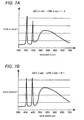
- FIG. 7A is a graph illustrating a spectral intensity of illuminating light when a light intensity ratio of LD1: LD2 is 1:4, and FIG. 7B is a graph illustrating a spectral intensity of illuminating light when a light intensity ratio of LD1: LD2 is 4:1. If the light intensity of the LD2 is increased as compared with the light intensity of the LD1, the illuminating light becomes a bluish light and as a result, the color tone of the observation image is changed in accordance with the light intensity ratio.
- the color tone of the observation image is corrected in accordance with the color shade of the illuminating light that is changed by the set light intensity ratio (S6), so that the observation image is not affected by the change in the color shade of the illuminating light.
- the control module 71 outputs the information of the light intensity ratio set by the optimal light intensity ratio setting module 77 to the color tone correcting module 83 together with the image signal of the observation image.
- the color tone correcting table for every light intensity ratio is prepared in the setting information storing module 79, and the color tone correcting module 83 selectively refers to the color tone correcting table corresponding to the set light intensity ratio to correct the change in the color tone of the image (increase in the blue color) to be eliminated.
- coefficient a ij of the correcting matrix A is set to eliminate the change in the color shade of the illuminating light by the change in the light intensity ratio, so that a plurality kinds of correction matrixes A corresponding to the plurality kinds of light intensity ratios are prepared in advance.
- the information of the correcting matrixes is stored in the setting information storing module 79.
- the control module 71 uses the selected correcting matrix A to correct the RGB brightness values of each of the pixels of the observation image and outputs the corrected image to be obtained on the monitor 15.
- the control module 71 continues the above procedures until the observation of the lesion area is completed (S7). Further, when another lesion area is found, the above procedures S4 to S6 are repeated. The procedures by the above sequence are performed until the observation is completed (S8).
- the color tone of the observation image is corrected in accordance with the set light intensity ratio. Therefore, even though any light intensity ratio is set, the image information may always be obtained as the observation image under constant color shade of the illuminating light. Accordingly, it is possible to always perform accurate endoscopic diagnosis.
- various image processing that are subjected to the captured image for example, a spectral endoscope image processing that creates a new observation image from the image intensity of a specific wavelength set (three primary colors), enhancement processing of various specific portions, or pseudo color processing is not affected by the change in the color shade of the illuminating light caused by changing the light intensity ratio of the laser light sources LD1, LD2.
- the endoscopic device with the present configuration newly includes a featured image region extracting module 81 that extracts a specific featured image region from the image signal.
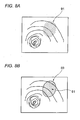
- FIG. 8A is an example of an observation image and shows an aspect that the blood capillary of a superficial portion of the mucous membrane in the image is displayed as a micro dot pattern.
- the dot pattern 91 that is the information of the blood capillary is brown as compared with the color of the surrounding pixels. Therefore, as shown in FIG. 8B , the featured image region 93 that is a blood capillary region may be selectively extracted by performing the image processing based on the color change information with respect to the surrounding pixels by the featured image region extracting module 81.
- the control module 71 appropriately sets the light intensity ratio of the illuminating light so that the extracted featured image region 93 has a high S/N.
- the optimal light intensity ratio setting module 77 sets the optimal light intensity ratio by referring to the light intensity ratio for emphasizing the blood vessel stored in the setting information storing module 79 in advance.
- the light intensity ratio for emphasizing the blood vessel is a light intensity ratio in which that the intensity of the light emitted from the LD2 is set to be larger than the LD1 in order to emphasize the blood vessel of a superficial portion of the mucous membrane.
- the control module 71 controls the light source control module 59 to have a set optimal light intensity ratio to emit desired illuminating light from the laser light sources LD1, LD2.
- the color tone correcting module 83 selects a correcting matrix, as described above, to correct the RGB signal value using the selected correcting matrix.
- an observation image that easily diagnoses the object to be observed is obtained. Further, the change in the color tone occurring in the observation image caused by the change in the light intensity ratio is corrected to obtain the same observation image as the illuminated by the illuminating light with the same color tone. Therefore, it is possible to increase the accuracy of the endoscopic diagnosis.
- the featured image region 93 is extracted based on the color change in the observation image, especially, based on the information of a R signal value, a G signal value, and a B signal value
- the featured image region including the blood capillary or micro pattern is simply extracted by calculating a ratio of the B signal value and the G signal value to which the blood vessel or the micro pattern of a superficial portion of the mucous membrane is emphasized to be displayed regardless of the information of the color signal.
- the high frequency component may be extracted from the observation image to determine the featured image region 93.
- the high frequency component region for example, is obtained by extracting a predetermined frequency component from a spectrum image, which is obtained by performing the two-dimensional Fourier transformation, using a mask processing and then performing inverse Fourier transformation on the extract result.
- the light intensity ratio of the light emitted from the laser light sources LD1, LD2 is changed, the brightness contrast of the observation image is changed. Therefore, while measuring the light intensity ratio where the brightness contrast is at the maximum so as to be found, the light intensity ratio having the maximum brightness contrast is ultimately determined.
- FIGS. 9A and 9B Explanatory diagrams illustrating specific procedures that calculate an optimal light intensity ratio are illustrated in FIGS. 9A and 9B .
- All of three kinds of light intensity ratios of an arbitrary light intensity ratio ⁇ , a light intensity ratio ⁇ - ⁇ in which a predetermined amount is subtracted from the arbitrary light intensity ratio ⁇ , and a light intensity ratio ⁇ + ⁇ in which the predetermined amount is added to the arbitrary light intensity ratio ⁇ are determined and the illuminating light is sequentially set with the light intensity ratios.
- the observation images by the illuminating light set with the light intensity ratios are captured to calculate the brightness contrast of three captured observation images.
- the light intensity ratio when the brightness contrast is increased in a direction where the light intensity ratio is reduced from the light intensity ratio ⁇ , the light intensity ratio is controlled to be reduced by the predetermined amount. In contrast, when the brightness contrast is increased in a direction where the light intensity ratio is increased from the light intensity ratio ⁇ , the light intensity ratio is controlled to be increased by the predetermined amount. Further, with respect to the reduced or increased light intensity ratio, the above-mentioned procedures are repeated.
- the control module 71 obtains the observation image irradiated with the set optimal light intensity ratio and outputs the information of the set optimal light intensity ratio to the color tone correcting module 83 together with the image signal of the observation image.
- the color tone correcting module 83 as described above, corrects the change in the color tone of the observation image to be eliminated by selectively referring to the color tone correction table corresponding to the set light intensity ratio.
- the present invention is not limited to the above exemplary embodiments, but the combinations of the components of the exemplary embodiments or change or application based on the description of the specification or the known technology are also included in the present invention.
- a white light source such as a xenon lamp or a halogen lamp
- a semiconductor light source such as a light emitting diode or a laser light source that emits a specific wavelength light
- the observation image may be corrected without changing the color tone of the observation image. Therefore, the subject may be observed with the illuminating light at an optimal light intensity ratio, and accurate endoscope diagnosis may be achieved.
- the light intensity ratio may be appropriately changed at the time of near view imaging having short imaging distance and at the time of distant view imaging having a long imaging distance. Therefore, for example, the near view imaging that is required to perform the narrow band imaging and the distant view imaging where the distance portion is tend to be dark are performed by the illuminating light at an optimal light intensity ratio so that the color tone of the observation image is not varied in accordance with the distance.
- the imaging distance may be simply and precisely obtained from the information of the AE value and the information of the illuminating light intensity.
- the color tone correcting module corrects the color tone of the image signal using the correction information of the correction information storing module, to simply eliminate the change in the color tone of the observation image due to the set light intensity ratio.
- the color signal values of the observation image is corrected using matrix correction with high degree of freedom of a design so that various color tone adjustment may be easily applied.
- the featured image region may be observed by the illuminating light having an optimal light intensity ratio, and thus the change in the color tone of the observation image is not caused by the change in the light intensity ratio. Therefore, the featured image region may be precisely diagnosed.
- an image region having different color from the surround pixel may be set as the featured image region.
- an image region which is turned in brown due to lots of the locally generated blood capillaries of a superficial portion of the mucous membrane may be set as the featured image region.
- the blood capillary of a superficial portion of the mucous membrane may be observed with a standard degree of emphasis.
- an image region having a high frequency component such as a region in which lots of the blood capillaries or micro patterns of a superficial portion of the mucous membrane locally appear is set as the featured image region.
- the featured image region is extracted based on the respective color signal values of the captured image signal. Therefore, various extracting algorism may be used, which gives lots of options for extract processing.
- the endoscopic device by calculating a ratio of the B signal value and the G signal value displayed by emphasizing the blood capillary or a micro pattern of a superficial portion of the mucous membrane, the location of the blood capillary or a micro pattern of the superficial portion of the mucous membrane is determined. Therefore, if the ratio of the B signal value and the G signal value is used, the featured image region may be simply extracted.
- the high frequency component may be precisely detected.
- the first illuminating light having a broad spectrum is obtained and the color rendering properties is improved.
- the optical system is made simple and the light emitted from the second light source may be added without largely affecting the first illuminating light by the emitted light of the first light source.
- the subject is illuminated by visible light having a short wavelength from the second light source to obtain an observation image in which the blood capillary or the micro pattern of the superficial portion of the mucous membrane is emphasized, which increases the accuracy of the diagnosis.
Landscapes
- Health & Medical Sciences (AREA)
- Life Sciences & Earth Sciences (AREA)
- Surgery (AREA)
- Engineering & Computer Science (AREA)
- Physics & Mathematics (AREA)
- Veterinary Medicine (AREA)
- General Health & Medical Sciences (AREA)
- Public Health (AREA)
- Pathology (AREA)
- Animal Behavior & Ethology (AREA)
- Biophysics (AREA)
- Biomedical Technology (AREA)
- Heart & Thoracic Surgery (AREA)
- Medical Informatics (AREA)
- Molecular Biology (AREA)
- Radiology & Medical Imaging (AREA)
- Nuclear Medicine, Radiotherapy & Molecular Imaging (AREA)
- Optics & Photonics (AREA)
- Signal Processing (AREA)
- Vascular Medicine (AREA)
- Mathematical Physics (AREA)
- Artificial Intelligence (AREA)
- Computer Vision & Pattern Recognition (AREA)
- Physiology (AREA)
- Psychiatry (AREA)
- Endoscopes (AREA)
- Instruments For Viewing The Inside Of Hollow Bodies (AREA)
Applications Claiming Priority (1)
| Application Number | Priority Date | Filing Date | Title |
|---|---|---|---|
| JP2011174818A JP5450527B2 (ja) | 2011-08-10 | 2011-08-10 | 内視鏡装置 |
Publications (1)
| Publication Number | Publication Date |
|---|---|
| EP2556790A1 true EP2556790A1 (fr) | 2013-02-13 |
Family
ID=46639354
Family Applications (1)
| Application Number | Title | Priority Date | Filing Date |
|---|---|---|---|
| EP20120178513 Withdrawn EP2556790A1 (fr) | 2011-08-10 | 2012-07-30 | Dispositif endoscopique |
Country Status (3)
| Country | Link |
|---|---|
| US (2) | US20130041218A1 (fr) |
| EP (1) | EP2556790A1 (fr) |
| JP (1) | JP5450527B2 (fr) |
Cited By (3)
| Publication number | Priority date | Publication date | Assignee | Title |
|---|---|---|---|---|
| CN105339828A (zh) * | 2013-06-27 | 2016-02-17 | 奥林巴斯株式会社 | 观察装置 |
| US20160377856A1 (en) * | 2013-12-25 | 2016-12-29 | Olympus Corporation | Optical scanning observation apparatus |
| EP3278717A4 (fr) * | 2015-05-20 | 2018-12-05 | Sony Olympus Medical Solutions Inc. | Dispositif de traitement du signal et système d'observation médical |
Families Citing this family (55)
| Publication number | Priority date | Publication date | Assignee | Title |
|---|---|---|---|---|
| CA3162577C (fr) | 2008-05-20 | 2023-09-26 | University Health Network | Dispositif et procede pour imagerie et surveillance par fluorescence |
| JP6168879B2 (ja) * | 2013-06-27 | 2017-07-26 | オリンパス株式会社 | 内視鏡装置、内視鏡装置の作動方法及びプログラム |
| WO2015005277A1 (fr) * | 2013-07-11 | 2015-01-15 | オリンパスメディカルシステムズ株式会社 | Dispositif de source de lumière |
| JP5925169B2 (ja) | 2013-09-27 | 2016-05-25 | 富士フイルム株式会社 | 内視鏡システム及びその作動方法並びに内視鏡用光源装置 |
| JP6013382B2 (ja) * | 2014-02-27 | 2016-10-25 | 富士フイルム株式会社 | 内視鏡システム及びその作動方法 |
| JP5968944B2 (ja) | 2014-03-31 | 2016-08-10 | 富士フイルム株式会社 | 内視鏡システム、プロセッサ装置、光源装置、内視鏡システムの作動方法、プロセッサ装置の作動方法、光源装置の作動方法 |
| JP6412709B2 (ja) * | 2014-04-02 | 2018-10-24 | オリンパス株式会社 | 観察画像取得システム |
| US10702128B2 (en) | 2014-07-02 | 2020-07-07 | Xenocor, Inc. | Medical borescopes and related tip assemblies |
| US9943214B2 (en) | 2014-07-02 | 2018-04-17 | Xenocor, Inc. | Medical borescopes and related methods and systems |
| WO2016011534A1 (fr) | 2014-07-24 | 2016-01-28 | University Health Network | Collecte et analyse de données à des fins de diagnostic |
| JP6587624B2 (ja) * | 2014-09-26 | 2019-10-09 | テルモ株式会社 | 断層像形成装置および制御方法 |
| WO2016098139A1 (fr) * | 2014-12-16 | 2016-06-23 | オリンパス株式会社 | Dispositif d'observation à balayage laser |
| JP6616071B2 (ja) * | 2014-12-22 | 2019-12-04 | 富士フイルム株式会社 | 内視鏡用のプロセッサ装置、内視鏡用のプロセッサ装置の作動方法、内視鏡用の制御プログラム |
| JP6386939B2 (ja) * | 2015-02-27 | 2018-09-05 | 富士フイルム株式会社 | 内視鏡光源装置、内視鏡システム、及び内視鏡光源装置の作動方法 |
| CN104978717A (zh) * | 2015-06-11 | 2015-10-14 | 沈阳东软医疗系统有限公司 | Ct重建图像的处理方法、装置及设备 |
| JP6568942B2 (ja) * | 2015-07-23 | 2019-08-28 | オリンパス株式会社 | 撮像システム及び内視鏡システム |
| CA3023772A1 (fr) | 2016-05-13 | 2017-11-16 | Smith & Nephew Plc | Appareil de surveillance et de therapie de plaie active par un capteur |
| US11690570B2 (en) | 2017-03-09 | 2023-07-04 | Smith & Nephew Plc | Wound dressing, patch member and method of sensing one or more wound parameters |
| EP3592230A1 (fr) | 2017-03-09 | 2020-01-15 | Smith & Nephew PLC | Appareil et procédé d'imagerie du sang dans une région cible de tissu |
| EP3592219B1 (fr) | 2017-03-09 | 2023-05-10 | Smith & Nephew plc | Dispositif et appareil de détermination de pression de perfusion cutanée |
| US11883262B2 (en) | 2017-04-11 | 2024-01-30 | Smith & Nephew Plc | Component positioning and stress relief for sensor enabled wound dressings |
| US11791030B2 (en) | 2017-05-15 | 2023-10-17 | Smith & Nephew Plc | Wound analysis device and method |
| WO2018210693A1 (fr) | 2017-05-15 | 2018-11-22 | Smith & Nephew Plc | Système de thérapie de plaie par pression négative utilisant un grossissement vidéo eulérien |
| JP7189159B2 (ja) | 2017-06-23 | 2022-12-13 | スミス アンド ネフュー ピーエルシー | センサを有効化した創傷モニタリングまたは治療のためのセンサの配置 |
| GB201804502D0 (en) | 2018-03-21 | 2018-05-02 | Smith & Nephew | Biocompatible encapsulation and component stress relief for sensor enabled negative pressure wound therapy dressings |
| GB201809007D0 (en) | 2018-06-01 | 2018-07-18 | Smith & Nephew | Restriction of sensor-monitored region for sensor-enabled wound dressings |
| AU2018312883B2 (en) | 2017-08-10 | 2024-06-13 | Smith & Nephew Plc | Positioning of sensors for sensor enabled wound monitoring or therapy |
| GB201718870D0 (en) | 2017-11-15 | 2017-12-27 | Smith & Nephew Inc | Sensor enabled wound therapy dressings and systems |
| JP7653254B2 (ja) | 2017-09-10 | 2025-03-28 | スミス アンド ネフュー ピーエルシー | 封入を検査するためのシステムおよび方法、ならびにセンサを装備した創傷被覆材内の構成要素 |
| GB201804971D0 (en) | 2018-03-28 | 2018-05-09 | Smith & Nephew | Electrostatic discharge protection for sensors in wound therapy |
| GB201718859D0 (en) | 2017-11-15 | 2017-12-27 | Smith & Nephew | Sensor positioning for sensor enabled wound therapy dressings and systems |
| JP7282079B2 (ja) | 2017-09-27 | 2023-05-26 | スミス アンド ネフュー ピーエルシー | センサが使用可能な陰圧創傷監視および療法装置のph感知 |
| WO2019072531A1 (fr) | 2017-09-28 | 2019-04-18 | Smith & Nephew Plc | Neurostimulation et surveillance à l'aide d'un appareil de surveillance et de traitement de plaie activé par un capteur |
| JP6891294B2 (ja) | 2017-11-13 | 2021-06-18 | 富士フイルム株式会社 | 内視鏡システム及びその作動方法 |
| WO2019096828A1 (fr) | 2017-11-15 | 2019-05-23 | Smith & Nephew Plc | Pansements et systèmes de surveillance et/ou de traitement de plaie activés à capteur intégré |
| GB201814011D0 (en) | 2018-08-29 | 2018-10-10 | Smith & Nephew | Componet positioning and encapsulation for sensor enabled wound dressings |
| GB2592508B (en) | 2018-09-12 | 2022-08-31 | Smith & Nephew | Device, apparatus and method of determining skin perfusion pressure |
| JP6987724B2 (ja) * | 2018-09-13 | 2022-01-05 | Hoya株式会社 | 光分配コネクタ、および内視鏡システム |
| EP3856104B1 (fr) | 2018-09-28 | 2025-08-06 | T.J.Smith And Nephew, Limited | Fibres optiques permettant la détection optique à travers des pansements de plaie |
| GB201816838D0 (en) | 2018-10-16 | 2018-11-28 | Smith & Nephew | Systems and method for applying biocompatible encapsulation to sensor enabled wound monitoring and therapy dressings |
| GB201820927D0 (en) | 2018-12-21 | 2019-02-06 | Smith & Nephew | Wound therapy systems and methods with supercapacitors |
| GB201901242D0 (en) | 2019-01-30 | 2019-03-20 | Smith & Nephew | Optical sensing systems and methods for sensing enabled wound dressings and systems |
| WO2020157103A1 (fr) | 2019-01-30 | 2020-08-06 | Smith & Nephew Plc | Pansements et systèmes intégrés à des capteurs |
| GB2597148B (en) | 2019-03-18 | 2022-12-21 | Smith & Nephew | Design rules for sensor integrated substrates |
| EP3941346B1 (fr) | 2019-03-19 | 2026-05-06 | Smith & Nephew PLC | Systèmes et méthodes de mesure de l'impédance des tissus |
| JP7163243B2 (ja) * | 2019-04-23 | 2022-10-31 | 富士フイルム株式会社 | プロセッサ装置及び内視鏡システム並びにプロセッサ装置の作動方法 |
| JP7344976B2 (ja) * | 2019-10-04 | 2023-09-14 | 富士フイルム株式会社 | 内視鏡システム及びその作動方法 |
| GB201914443D0 (en) | 2019-10-07 | 2019-11-20 | Smith & Nephew | Sensor enabled negative pressure wound monitoring apparatus with different impedances inks |
| GB201918856D0 (en) | 2019-12-19 | 2020-02-05 | Smith & Nephew | Sensor integrated dressings and systems |
| EP4082419A4 (fr) * | 2019-12-26 | 2023-06-07 | FUJIFILM Corporation | Système d'endoscope et procédé de fonctionnement associé |
| GB202003203D0 (en) | 2020-03-05 | 2020-04-22 | Smith & Nephew | Sensor integrated dressings and systems |
| EP4139904A1 (fr) | 2020-04-21 | 2023-03-01 | T.J. Smith and Nephew, Limited | Gestion de traitement de plaie mettant en oeuvre une superposition par réalité augmentée |
| GB202007391D0 (en) | 2020-05-19 | 2020-07-01 | Smith & Nephew | Patient protection from unsafe electric current in sensor integrated dressings and systems |
| WO2022150465A1 (fr) * | 2021-01-06 | 2022-07-14 | Intuitive Surgical Operations, Inc. | Dispositifs et procédés pour créer un éclairage uniforme |
| CN116746865A (zh) * | 2023-06-15 | 2023-09-15 | 微创优通医疗科技(上海)有限公司 | 一种内窥镜用的照明组件、照明调节方法及内窥镜 |
Citations (5)
| Publication number | Priority date | Publication date | Assignee | Title |
|---|---|---|---|---|
| EP1488732A1 (fr) * | 2003-06-17 | 2004-12-22 | Olympus Corporation | Dispositif électronique pour endoscope |
| EP2020202A2 (fr) * | 2007-07-31 | 2009-02-04 | Olympus Medical Systems Corp. | Appareil médical |
| WO2011004801A1 (fr) * | 2009-07-06 | 2011-01-13 | 富士フイルム株式会社 | Dispositif d'éclairage pour endoscope et dispositif d'endoscope |
| EP2301413A1 (fr) * | 2009-09-24 | 2011-03-30 | Fujifilm Corporation | Appareil d'endoscopie |
| EP2301418A1 (fr) * | 2009-09-29 | 2011-03-30 | Fujifilm Corporation | Appareil médical et appareil d'endoscope |
Family Cites Families (68)
| Publication number | Priority date | Publication date | Assignee | Title |
|---|---|---|---|---|
| JPH0435855Y2 (fr) * | 1985-07-19 | 1992-08-25 | ||
| JPH0783486B2 (ja) | 1986-02-06 | 1995-09-06 | 株式会社東芝 | 内視鏡装置 |
| JPS63155984A (ja) | 1986-12-19 | 1988-06-29 | Olympus Optical Co Ltd | 電子内視鏡用ホワイトバランス回路 |
| JPS63286131A (ja) * | 1987-05-18 | 1988-11-22 | Asahi Optical Co Ltd | 内視鏡の色調調整装置 |
| JPH0640174B2 (ja) | 1988-07-20 | 1994-05-25 | 株式会社東芝 | 内視鏡装置 |
| JP2940827B2 (ja) | 1988-09-07 | 1999-08-25 | オリンパス光学工業株式会社 | 医療用画像ファイリング装置 |
| US5282030A (en) * | 1990-11-19 | 1994-01-25 | Olympus Optical Co., Ltd. | Endoscopic image processor and endoscopic image processing method |
| JP3126996B2 (ja) * | 1991-04-12 | 2001-01-22 | オリンパス光学工業株式会社 | 内視鏡画像の処理方法 |
| US5894322A (en) | 1992-01-15 | 1999-04-13 | Olympus Optical Co., Ltd. | Endoscope system with improved controller |
| US5749830A (en) | 1993-12-03 | 1998-05-12 | Olympus Optical Co., Ltd. | Fluorescent endoscope apparatus |
| US5864361A (en) * | 1993-12-24 | 1999-01-26 | Asahi Kogaku Kogyo Kabushiki Kaisha | Video endoscope system with color tone correction |
| JP2001137172A (ja) | 1999-11-11 | 2001-05-22 | Fuji Photo Film Co Ltd | 蛍光検出装置 |
| AU2001259435A1 (en) * | 2000-05-03 | 2001-11-12 | Stephen T Flock | Optical imaging of subsurface anatomical structures and biomolecules |
| JP3864035B2 (ja) * | 2000-05-19 | 2006-12-27 | オリンパス株式会社 | 内視鏡システム |
| US6577073B2 (en) | 2000-05-31 | 2003-06-10 | Matsushita Electric Industrial Co., Ltd. | Led lamp |
| JP3583731B2 (ja) | 2000-07-21 | 2004-11-04 | オリンパス株式会社 | 内視鏡装置および光源装置 |
| US7892169B2 (en) | 2000-07-21 | 2011-02-22 | Olympus Corporation | Endoscope apparatus |
| AU2001285398A1 (en) | 2000-08-04 | 2002-02-18 | Color Kinetics Incorporated | Ultraviolet light emitting diode systems and methods |
| JP2002153414A (ja) | 2000-11-17 | 2002-05-28 | Asahi Optical Co Ltd | 電子内視鏡及び電子内視鏡システム |
| US7172553B2 (en) * | 2001-05-16 | 2007-02-06 | Olympus Corporation | Endoscope system using normal light and fluorescence |
| JP4054222B2 (ja) * | 2002-06-05 | 2008-02-27 | オリンパス株式会社 | 内視鏡装置用光源装置 |
| JP3847319B2 (ja) | 2002-07-03 | 2006-11-22 | 株式会社松風 | 歯科写真撮影システム |
| JP2004128444A (ja) * | 2002-07-31 | 2004-04-22 | Shin Etsu Handotai Co Ltd | 発光素子及びそれを用いた照明装置 |
| US7159987B2 (en) * | 2003-04-21 | 2007-01-09 | Seiko Epson Corporation | Display device, lighting device and projector |
| US7005679B2 (en) | 2003-05-01 | 2006-02-28 | Cree, Inc. | Multiple component solid state white light |
| JP2005006856A (ja) | 2003-06-18 | 2005-01-13 | Olympus Corp | 内視鏡装置 |
| JP2005122237A (ja) | 2003-10-14 | 2005-05-12 | Olympus Corp | 検査装置管理方法及びサーバ装置 |
| JP2005124823A (ja) | 2003-10-23 | 2005-05-19 | Olympus Corp | 内視鏡装置 |
| JP4554944B2 (ja) | 2004-01-15 | 2010-09-29 | Hoya株式会社 | 内視鏡装置 |
| US20070171375A1 (en) * | 2004-02-27 | 2007-07-26 | Matsushita Electric Industrial Co., Ltd. | Display device |
| JP4452607B2 (ja) | 2004-03-05 | 2010-04-21 | 順一 島田 | 照明装置、フィルタ装置、画像表示装置 |
| WO2005104926A1 (fr) | 2004-04-30 | 2005-11-10 | J. Morita Manufacturing Corporation | Appareil d'observation d'un corps vivant, système de formation d'images intra oral et dispositif de traitement médical |
| JP2006002115A (ja) | 2004-06-21 | 2006-01-05 | Nagaoka Univ Of Technology | 固体蛍光材料 |
| US7646029B2 (en) | 2004-07-08 | 2010-01-12 | Philips Solid-State Lighting Solutions, Inc. | LED package methods and systems |
| US20080262316A1 (en) | 2004-07-28 | 2008-10-23 | Kyocera Corporation | Light Source Apparatus and Endoscope Provided with Light Source Apparatus |
| US8602971B2 (en) | 2004-09-24 | 2013-12-10 | Vivid Medical. Inc. | Opto-Electronic illumination and vision module for endoscopy |
| US7758224B2 (en) | 2004-10-01 | 2010-07-20 | Nichia Corporation | Light emitting device |
| JP2006122335A (ja) | 2004-10-28 | 2006-05-18 | Morita Mfg Co Ltd | カメラ装置 |
| US7433115B2 (en) | 2004-12-15 | 2008-10-07 | Nichia Corporation | Light emitting device |
| JP2006173324A (ja) | 2004-12-15 | 2006-06-29 | Nichia Chem Ind Ltd | 発光装置 |
| JP4786910B2 (ja) | 2005-02-07 | 2011-10-05 | Hoya株式会社 | 電子内視鏡 |
| US8279275B2 (en) | 2005-05-11 | 2012-10-02 | Olympus Medical Systems Corp. | Signal processing device for biological observation apparatus |
| JP4504324B2 (ja) | 2005-05-13 | 2010-07-14 | オリンパスメディカルシステムズ株式会社 | 生体観測装置 |
| JP4723281B2 (ja) | 2005-05-16 | 2011-07-13 | Hoya株式会社 | 電子内視鏡システム |
| JP5114024B2 (ja) * | 2005-08-31 | 2013-01-09 | オリンパス株式会社 | 光イメージング装置 |
| JP4761899B2 (ja) | 2005-09-12 | 2011-08-31 | Hoya株式会社 | 電子内視鏡システム |
| JP4916160B2 (ja) | 2005-11-14 | 2012-04-11 | オリンパス株式会社 | 内視鏡装置 |
| JP4922636B2 (ja) | 2006-03-24 | 2012-04-25 | オリンパスメディカルシステムズ株式会社 | 内視鏡 |
| EP2035745B1 (fr) | 2006-05-31 | 2020-04-29 | IDEAL Industries Lighting LLC | Dispositif d'eclairage avec controle des couleurs et procede d'eclairage |
| JP2007319442A (ja) | 2006-06-01 | 2007-12-13 | Fujifilm Corp | カプセル内視鏡システム、および画像処理装置 |
| JP2010506669A (ja) | 2006-10-20 | 2010-03-04 | フェムスイート, エルエルシー | 光学外科用デバイスおよびその使用方法 |
| CN101246876B (zh) | 2007-02-16 | 2010-05-19 | 厦门通士达照明有限公司 | 一种获得led灯的方法及led灯 |
| KR101460832B1 (ko) | 2007-05-08 | 2014-11-12 | 크리, 인코포레이티드 | 조명 장치 및 조명 방법 |
| JP5133595B2 (ja) | 2007-05-15 | 2013-01-30 | オリンパスメディカルシステムズ株式会社 | 照明光検出用光学系並びにそれを備えた光学装置及び内視鏡装置 |
| CN101347324B (zh) * | 2007-07-17 | 2012-05-30 | 鸿富锦精密工业(深圳)有限公司 | 内窥镜装置 |
| JP4845824B2 (ja) | 2007-07-17 | 2011-12-28 | オリンパスメディカルシステムズ株式会社 | 内視鏡 |
| JP5019289B2 (ja) | 2007-08-10 | 2012-09-05 | オリンパス株式会社 | 光ファイバ照明装置 |
| JP2009056248A (ja) | 2007-09-03 | 2009-03-19 | Fujifilm Corp | 光源装置、および光源装置の駆動制御方法、並びに内視鏡 |
| JP2009153621A (ja) | 2007-12-25 | 2009-07-16 | Olympus Corp | 生体観察装置および内視鏡装置 |
| JP2009153712A (ja) | 2007-12-26 | 2009-07-16 | Olympus Corp | 光源装置およびそれを備えた内視鏡装置 |
| JP5117878B2 (ja) | 2008-02-13 | 2013-01-16 | 富士フイルム株式会社 | 内視鏡光源装置 |
| JP5424570B2 (ja) * | 2008-04-10 | 2014-02-26 | Hoya株式会社 | 電子内視鏡用プロセッサ、ビデオスコープ及び電子内視鏡装置 |
| DE602009001103D1 (de) | 2008-06-04 | 2011-06-01 | Fujifilm Corp | Beleuchtungsvorrichtung zur Verwendung in Endoskopen |
| JP5173663B2 (ja) | 2008-08-07 | 2013-04-03 | オリンパス株式会社 | 光源装置およびこれを用いた内視鏡装置 |
| JP5117353B2 (ja) * | 2008-11-07 | 2013-01-16 | オリンパス株式会社 | 画像処理装置、画像処理プログラムおよび画像処理方法 |
| JP5271062B2 (ja) * | 2008-12-09 | 2013-08-21 | 富士フイルム株式会社 | 内視鏡装置およびその作動方法 |
| JP5401205B2 (ja) * | 2009-08-10 | 2014-01-29 | 富士フイルム株式会社 | 内視鏡装置 |
| JP2011200367A (ja) * | 2010-03-25 | 2011-10-13 | Fujifilm Corp | 画像撮像方法および装置 |
-
2011
- 2011-08-10 JP JP2011174818A patent/JP5450527B2/ja active Active
-
2012
- 2012-07-30 EP EP20120178513 patent/EP2556790A1/fr not_active Withdrawn
- 2012-07-30 US US13/562,149 patent/US20130041218A1/en not_active Abandoned
-
2015
- 2015-04-14 US US14/686,687 patent/US9675238B2/en active Active
Patent Citations (6)
| Publication number | Priority date | Publication date | Assignee | Title |
|---|---|---|---|---|
| EP1488732A1 (fr) * | 2003-06-17 | 2004-12-22 | Olympus Corporation | Dispositif électronique pour endoscope |
| EP2020202A2 (fr) * | 2007-07-31 | 2009-02-04 | Olympus Medical Systems Corp. | Appareil médical |
| WO2011004801A1 (fr) * | 2009-07-06 | 2011-01-13 | 富士フイルム株式会社 | Dispositif d'éclairage pour endoscope et dispositif d'endoscope |
| JP2011010998A (ja) | 2009-07-06 | 2011-01-20 | Fujifilm Corp | 内視鏡用照明装置および内視鏡装置 |
| EP2301413A1 (fr) * | 2009-09-24 | 2011-03-30 | Fujifilm Corporation | Appareil d'endoscopie |
| EP2301418A1 (fr) * | 2009-09-29 | 2011-03-30 | Fujifilm Corporation | Appareil médical et appareil d'endoscope |
Cited By (9)
| Publication number | Priority date | Publication date | Assignee | Title |
|---|---|---|---|---|
| CN105339828A (zh) * | 2013-06-27 | 2016-02-17 | 奥林巴斯株式会社 | 观察装置 |
| EP3015899A4 (fr) * | 2013-06-27 | 2017-02-15 | Olympus Corporation | Dispositif d'observation |
| US10314462B2 (en) | 2013-06-27 | 2019-06-11 | Olympus Corporation | Observation apparatus |
| US20160377856A1 (en) * | 2013-12-25 | 2016-12-29 | Olympus Corporation | Optical scanning observation apparatus |
| EP3087900A4 (fr) * | 2013-12-25 | 2017-11-15 | Olympus Corporation | Dispositif d'observation du type à balayage optique |
| US10151914B2 (en) | 2013-12-25 | 2018-12-11 | Olympus Corporation | Optical scanning observation apparatus |
| EP3278717A4 (fr) * | 2015-05-20 | 2018-12-05 | Sony Olympus Medical Solutions Inc. | Dispositif de traitement du signal et système d'observation médical |
| US11141043B2 (en) | 2015-05-20 | 2021-10-12 | Sony Olympus Medical Solutions Inc. | Signal processing device and medical observation system |
| US12226069B2 (en) | 2015-05-20 | 2025-02-18 | Sony Olympus Medical Solutions Inc. | Signal processing device and medical observation system |
Also Published As
| Publication number | Publication date |
|---|---|
| US20130041218A1 (en) | 2013-02-14 |
| US9675238B2 (en) | 2017-06-13 |
| JP5450527B2 (ja) | 2014-03-26 |
| JP2013034753A (ja) | 2013-02-21 |
| US20150216400A1 (en) | 2015-08-06 |
Similar Documents
| Publication | Publication Date | Title |
|---|---|---|
| US9675238B2 (en) | Endoscopic device | |
| US10335014B2 (en) | Endoscope system, processor device, and method for operating endoscope system | |
| JP5303012B2 (ja) | 内視鏡システム、内視鏡システムのプロセッサ装置及び内視鏡システムの作動方法 | |
| JP6461739B2 (ja) | 画像処理装置及び内視鏡システム並びに画像処理装置の作動方法 | |
| JP5670264B2 (ja) | 内視鏡システム、及び内視鏡システムの作動方法 | |
| EP2979618B1 (fr) | Dispositif de traitement de l'image de fonctionnement d'un système endoscopique | |
| US9629527B2 (en) | Endoscope system, processor device of endoscope system, and image processing method | |
| US9414739B2 (en) | Imaging apparatus for controlling fluorescence imaging in divided imaging surface | |
| JP5485215B2 (ja) | 内視鏡装置 | |
| EP2803313A1 (fr) | Dispositif de processeur, système d'endoscope et procédé de fonctionnement du système d'endoscope | |
| CN106163367B (zh) | 医用图像处理装置及其工作方法以及内窥镜系统 | |
| WO2018159083A1 (fr) | Système d'endoscope, dispositif de processeur, et procédé de fonctionnement de système d'endoscope | |
| CN110868908B (zh) | 医用图像处理装置及内窥镜系统以及医用图像处理装置的工作方法 | |
| JP6392486B1 (ja) | 内視鏡システム | |
| EP2924971B1 (fr) | Dispositif de traitement d'images médicales et son procédé d'exploitation | |
| WO2016110984A1 (fr) | Dispositif de traitement d'image, procédé de fonctionnement de dispositif de traitement d'image, programme de fonctionnement de dispositif de traitement d'image, et dispositif d'endoscope | |
| JP6259747B2 (ja) | プロセッサ装置、内視鏡システム、プロセッサ装置の作動方法、及びプログラム | |
| JP6774550B2 (ja) | 内視鏡システム、プロセッサ装置、及び、内視鏡システムの作動方法 | |
| JP7235540B2 (ja) | 医療用画像処理装置及び医療用観察システム | |
| JP6425995B2 (ja) | 内視鏡システム及びその作動方法 | |
| JP6586206B2 (ja) | 内視鏡システム及びその作動方法 | |
| JP5970054B2 (ja) | 内視鏡システム、内視鏡システムの光源装置、及び内視鏡システムの作動方法 |
Legal Events
| Date | Code | Title | Description |
|---|---|---|---|
| PUAI | Public reference made under article 153(3) epc to a published international application that has entered the european phase |
Free format text: ORIGINAL CODE: 0009012 |
|
| AK | Designated contracting states |
Kind code of ref document: A1 Designated state(s): AL AT BE BG CH CY CZ DE DK EE ES FI FR GB GR HR HU IE IS IT LI LT LU LV MC MK MT NL NO PL PT RO RS SE SI SK SM TR |
|
| AX | Request for extension of the european patent |
Extension state: BA ME |
|
| 17P | Request for examination filed |
Effective date: 20130627 |
|
| RBV | Designated contracting states (corrected) |
Designated state(s): AL AT BE BG CH CY CZ DE DK EE ES FI FR GB GR HR HU IE IS IT LI LT LU LV MC MK MT NL NO PL PT RO RS SE SI SK SM TR |
|
| 17Q | First examination report despatched |
Effective date: 20140521 |
|
| STAA | Information on the status of an ep patent application or granted ep patent |
Free format text: STATUS: THE APPLICATION IS DEEMED TO BE WITHDRAWN |
|
| 18D | Application deemed to be withdrawn |
Effective date: 20150915 |