EP2556811A1 - Endplatte für Patientenauflagevorrichtung - Google Patents
Endplatte für Patientenauflagevorrichtung Download PDFInfo
- Publication number
- EP2556811A1 EP2556811A1 EP12188561A EP12188561A EP2556811A1 EP 2556811 A1 EP2556811 A1 EP 2556811A1 EP 12188561 A EP12188561 A EP 12188561A EP 12188561 A EP12188561 A EP 12188561A EP 2556811 A1 EP2556811 A1 EP 2556811A1
- Authority
- EP
- European Patent Office
- Prior art keywords
- patient
- extender
- end panel
- support apparatus
- relative
- Prior art date
- Legal status (The legal status is an assumption and is not a legal conclusion. Google has not performed a legal analysis and makes no representation as to the accuracy of the status listed.)
- Withdrawn
Links
- 230000004888 barrier function Effects 0.000 claims abstract description 40
- 239000004606 Fillers/Extenders Substances 0.000 claims description 168
- 239000004744 fabric Substances 0.000 description 15
- 230000000994 depressogenic effect Effects 0.000 description 4
- 230000007246 mechanism Effects 0.000 description 4
- 230000000717 retained effect Effects 0.000 description 4
- 239000007787 solid Substances 0.000 description 4
- 238000007373 indentation Methods 0.000 description 3
- 230000008859 change Effects 0.000 description 2
- 239000013013 elastic material Substances 0.000 description 2
- 230000000295 complement effect Effects 0.000 description 1
- 230000006835 compression Effects 0.000 description 1
- 238000007906 compression Methods 0.000 description 1
- 230000001419 dependent effect Effects 0.000 description 1
- 230000005484 gravity Effects 0.000 description 1
- 238000003780 insertion Methods 0.000 description 1
- 230000037431 insertion Effects 0.000 description 1
- 238000004519 manufacturing process Methods 0.000 description 1
- 230000013011 mating Effects 0.000 description 1
- 238000010297 mechanical methods and process Methods 0.000 description 1
- 230000005226 mechanical processes and functions Effects 0.000 description 1
- 238000012986 modification Methods 0.000 description 1
- 230000004048 modification Effects 0.000 description 1
- 230000007935 neutral effect Effects 0.000 description 1
- 238000003466 welding Methods 0.000 description 1
Images










Classifications
-
- A—HUMAN NECESSITIES
- A61—MEDICAL OR VETERINARY SCIENCE; HYGIENE
- A61G—TRANSPORT, PERSONAL CONVEYANCES, OR ACCOMMODATION SPECIALLY ADAPTED FOR PATIENTS OR DISABLED PERSONS; OPERATING TABLES OR CHAIRS; CHAIRS FOR DENTISTRY; FUNERAL DEVICES
- A61G7/00—Beds specially adapted for nursing; Devices for lifting patients or disabled persons
- A61G7/05—Parts, details or accessories of beds
- A61G7/0503—Holders, support devices for receptacles, e.g. for drainage or urine bags
-
- A—HUMAN NECESSITIES
- A61—MEDICAL OR VETERINARY SCIENCE; HYGIENE
- A61G—TRANSPORT, PERSONAL CONVEYANCES, OR ACCOMMODATION SPECIALLY ADAPTED FOR PATIENTS OR DISABLED PERSONS; OPERATING TABLES OR CHAIRS; CHAIRS FOR DENTISTRY; FUNERAL DEVICES
- A61G7/00—Beds specially adapted for nursing; Devices for lifting patients or disabled persons
- A61G7/002—Beds specially adapted for nursing; Devices for lifting patients or disabled persons having adjustable mattress frame
-
- A—HUMAN NECESSITIES
- A61—MEDICAL OR VETERINARY SCIENCE; HYGIENE
- A61G—TRANSPORT, PERSONAL CONVEYANCES, OR ACCOMMODATION SPECIALLY ADAPTED FOR PATIENTS OR DISABLED PERSONS; OPERATING TABLES OR CHAIRS; CHAIRS FOR DENTISTRY; FUNERAL DEVICES
- A61G7/00—Beds specially adapted for nursing; Devices for lifting patients or disabled persons
- A61G7/002—Beds specially adapted for nursing; Devices for lifting patients or disabled persons having adjustable mattress frame
- A61G7/018—Control or drive mechanisms
-
- A—HUMAN NECESSITIES
- A61—MEDICAL OR VETERINARY SCIENCE; HYGIENE
- A61G—TRANSPORT, PERSONAL CONVEYANCES, OR ACCOMMODATION SPECIALLY ADAPTED FOR PATIENTS OR DISABLED PERSONS; OPERATING TABLES OR CHAIRS; CHAIRS FOR DENTISTRY; FUNERAL DEVICES
- A61G7/00—Beds specially adapted for nursing; Devices for lifting patients or disabled persons
- A61G7/05—Parts, details or accessories of beds
-
- A—HUMAN NECESSITIES
- A61—MEDICAL OR VETERINARY SCIENCE; HYGIENE
- A61G—TRANSPORT, PERSONAL CONVEYANCES, OR ACCOMMODATION SPECIALLY ADAPTED FOR PATIENTS OR DISABLED PERSONS; OPERATING TABLES OR CHAIRS; CHAIRS FOR DENTISTRY; FUNERAL DEVICES
- A61G7/00—Beds specially adapted for nursing; Devices for lifting patients or disabled persons
- A61G7/05—Parts, details or accessories of beds
- A61G7/0506—Head or foot boards
-
- A—HUMAN NECESSITIES
- A61—MEDICAL OR VETERINARY SCIENCE; HYGIENE
- A61G—TRANSPORT, PERSONAL CONVEYANCES, OR ACCOMMODATION SPECIALLY ADAPTED FOR PATIENTS OR DISABLED PERSONS; OPERATING TABLES OR CHAIRS; CHAIRS FOR DENTISTRY; FUNERAL DEVICES
- A61G7/00—Beds specially adapted for nursing; Devices for lifting patients or disabled persons
- A61G7/05—Parts, details or accessories of beds
- A61G7/0507—Side-rails
-
- A—HUMAN NECESSITIES
- A61—MEDICAL OR VETERINARY SCIENCE; HYGIENE
- A61G—TRANSPORT, PERSONAL CONVEYANCES, OR ACCOMMODATION SPECIALLY ADAPTED FOR PATIENTS OR DISABLED PERSONS; OPERATING TABLES OR CHAIRS; CHAIRS FOR DENTISTRY; FUNERAL DEVICES
- A61G7/00—Beds specially adapted for nursing; Devices for lifting patients or disabled persons
- A61G7/05—Parts, details or accessories of beds
- A61G7/0507—Side-rails
- A61G7/0508—Side-rails characterised by a particular connection mechanism
- A61G7/051—Side-rails characterised by a particular connection mechanism pivoting sideward
-
- A—HUMAN NECESSITIES
- A61—MEDICAL OR VETERINARY SCIENCE; HYGIENE
- A61G—TRANSPORT, PERSONAL CONVEYANCES, OR ACCOMMODATION SPECIALLY ADAPTED FOR PATIENTS OR DISABLED PERSONS; OPERATING TABLES OR CHAIRS; CHAIRS FOR DENTISTRY; FUNERAL DEVICES
- A61G7/00—Beds specially adapted for nursing; Devices for lifting patients or disabled persons
- A61G7/05—Parts, details or accessories of beds
- A61G7/0507—Side-rails
- A61G7/0512—Side-rails characterised by customised length
- A61G7/0513—Side-rails characterised by customised length covering particular sections of the bed, e.g. one or more partial side-rail sections along the bed
-
- A—HUMAN NECESSITIES
- A61—MEDICAL OR VETERINARY SCIENCE; HYGIENE
- A61G—TRANSPORT, PERSONAL CONVEYANCES, OR ACCOMMODATION SPECIALLY ADAPTED FOR PATIENTS OR DISABLED PERSONS; OPERATING TABLES OR CHAIRS; CHAIRS FOR DENTISTRY; FUNERAL DEVICES
- A61G7/00—Beds specially adapted for nursing; Devices for lifting patients or disabled persons
- A61G7/05—Parts, details or accessories of beds
- A61G7/0507—Side-rails
- A61G7/0519—Side-rails stowable, e.g. underneath mattress
-
- A—HUMAN NECESSITIES
- A61—MEDICAL OR VETERINARY SCIENCE; HYGIENE
- A61G—TRANSPORT, PERSONAL CONVEYANCES, OR ACCOMMODATION SPECIALLY ADAPTED FOR PATIENTS OR DISABLED PERSONS; OPERATING TABLES OR CHAIRS; CHAIRS FOR DENTISTRY; FUNERAL DEVICES
- A61G7/00—Beds specially adapted for nursing; Devices for lifting patients or disabled persons
- A61G7/05—Parts, details or accessories of beds
- A61G7/0507—Side-rails
- A61G7/0524—Side-rails characterised by integrated accessories, e.g. bed control means, nurse call or reading lights
-
- A—HUMAN NECESSITIES
- A47—FURNITURE; DOMESTIC ARTICLES OR APPLIANCES; COFFEE MILLS; SPICE MILLS; SUCTION CLEANERS IN GENERAL
- A47C—CHAIRS; SOFAS; BEDS
- A47C21/00—Attachments for beds, e.g. sheet holders or bed-cover holders; Ventilating, cooling or heating means in connection with bedsteads or mattresses
- A47C21/08—Devices for prevention against falling-out, e.g. detachable side walls
-
- A—HUMAN NECESSITIES
- A61—MEDICAL OR VETERINARY SCIENCE; HYGIENE
- A61G—TRANSPORT, PERSONAL CONVEYANCES, OR ACCOMMODATION SPECIALLY ADAPTED FOR PATIENTS OR DISABLED PERSONS; OPERATING TABLES OR CHAIRS; CHAIRS FOR DENTISTRY; FUNERAL DEVICES
- A61G2203/00—General characteristics of devices
- A61G2203/70—General characteristics of devices with special adaptations, e.g. for safety or comfort
- A61G2203/72—General characteristics of devices with special adaptations, e.g. for safety or comfort for collision prevention
- A61G2203/723—Impact absorbing means, e.g. bumpers or airbags
-
- A—HUMAN NECESSITIES
- A61—MEDICAL OR VETERINARY SCIENCE; HYGIENE
- A61G—TRANSPORT, PERSONAL CONVEYANCES, OR ACCOMMODATION SPECIALLY ADAPTED FOR PATIENTS OR DISABLED PERSONS; OPERATING TABLES OR CHAIRS; CHAIRS FOR DENTISTRY; FUNERAL DEVICES
- A61G7/00—Beds specially adapted for nursing; Devices for lifting patients or disabled persons
- A61G7/002—Beds specially adapted for nursing; Devices for lifting patients or disabled persons having adjustable mattress frame
- A61G7/015—Beds specially adapted for nursing; Devices for lifting patients or disabled persons having adjustable mattress frame divided into different adjustable sections, e.g. for Gatch position
Definitions
- the present disclosure relates to bed ends for patient-support apparatuses. More specifically, the present disclosure relates to bed ends having members which are movable between a stowed position and a use position filling a gap between a siderail and the end panel of the patient-support apparatus.
- the main portion comprises a generally vertical surface having a curvilinear profile when viewed along a generally vertical axis and a generally horizontal slot formed in the generally vertical surface.
- the end panel further comprises an extender movable relative to the main portion to increase the size of the boundary structure.
- the extender comprises a generally vertical surface parallel to the generally vertical surface of the main portion.
- the extender further comprises a guide engaged with the slot to support the extender relative to the main portion for movement relative thereto.
- the extender comprises a first portion movable relative to the main portion and a second portion which is engaged with the first portion and extendable relative thereto.
- the first portion may comprise a first panel and a second panel.
- the first and second panels may include tracks.
- the second portion may be received between the panels and include guides received in the tracks to guide movement of the second portion relative to the first portion.
- the extender may comprise a generally planar flange configured to extend between a frame of the patient-support apparatus and a mattress supported on the patient-support apparatus.
- the patient-support apparatus may further comprise a frame including a first patient-support section and a second patient-support section movable relative to the first patient-support section to vary a size of a patient-support surface.
- the first portion of the extender may comprise an engagement pin and the first patient-support section may comprise a coupler configured to receive the engagement pin to couple the first portion of the extender to the first patient-support section.
- the patient-support apparatus may further comprise a siderail spaced apart from the end panel and a bracket releasably coupled to the siderail.
- the bracket may include a clamp configured to receive the second portion of the extender to position the extender to occupy a gap between the siderail and the main portion of the end panel.
- the clamp may be spring biased.
- the bracket may include an actuator actuable to overcome the spring bias to release the clamp.
- the coupler may include a slide movable between a closed position and an open position.
- the slide may be spring biased to the closed position.
- an end panel comprises a first portion configured to engage a portion of a patient-support apparatus to form a barrier and a second portion coupled to the first portion and movable relative thereto.
- the second portion may be movable between a first position adjacent the first portion and a second position wherein the second portion is positioned adjacent a patient-support surface.
- the second portion may extend vertically above the patient-support surface to form a barrier.
- the end panel may further comprise a detent assembly configured to maintain the second portion in the second position.
- the second portion may pivot relative to the first portion about a generally vertical axis.
- the detent assembly may comprise a receiver coupled to the first portion and a generally vertical pivot shaft defining a pivot axis coupled to the second portion.
- the pivot shaft may include a cross-member configured to engage the receiver when the second portion is in the second position.
- the second portion may be movable along the pivot axis to disengage the cross-member from the receiver to release the second portion.
- the detent assembly may comprise a first plate comprising a tab, the first plate coupled to the first portion and a second plate comprising at least one slot configured to engage the tab when the second portion is in the second position.
- the second portion may be movable along the pivot axis to disengage the slot from the tab to release the second portion.
- the second portion may translate relative to the first portion.
- the first portion may comprise a track and a slider engaged with the track.
- the slider may be slidable along the track and include a pivot support configured to support the second portion for pivotable movement relative thereto.
- the second portion may be pivotable about a generally horizontal axis between a vertical configuration and a horizontal configuration.
- an end panel may comprise a main portion configured to mount to the frame of a patient-support apparatus and an extender coupled to the main portion and configured to be coupled to a siderail of the patient-support apparatus to enclose a gap between the main portion and a siderail of the patient-support apparatus.
- the extender may be spring retractable. The extender may extend and retract with movement of the second patient-support section.
- the extender may comprise a fabric web coupled to a spring retractor, the spring retractor biased to retract the fabric.
- the extender may comprise a plurality of fabric webs, each fabric web coupled to a separate spring retractor, the spring retractors biased to retract the fabric.
- the extender further comprises a grip configured to couple to the siderail, wherein each web is coupled to the grip.
- an end panel 12 is mounted on a foot deck 14 of a patient-support apparatus 10, the end panel 12 including a body 16, a first extender 18, and a second extender 20 as shown in Fig. 1 .
- patient-support apparatus 10 is embodied as a hospital bed. Hospital bed 10 is shown in Fig. 1 with a foot end 24 positioned at the lower left side of the figure and a head end 26 at the upper right side of the figure.
- a patient occupies the hospital bed 10 in a supine position on a patient-support surface 22.
- the terms “head end” and “foot end” are used generally to provide orientation and do not refer to specific features of the hospital bed 10.
- the terms “patient left” and “patient right” are used to provide orientation relative to a patient positioned on the hospital bed 10 lying in a supine position.
- end panel 12 is oriented at the foot end 24 and an end panel 28 is oriented at a head end 26.
- Hospital bed 10 further includes four siderails: a right head rail 30, a right foot rail 32, a left head rail 34, and a left foot rail 36.
- Siderails 30, 32, 34 and 36 are movable between a barrier position as shown in Fig. 1 and a lowered position wherein the siderails 30, 32, 34 and 36 are below a top surface 38 of patient-support surface 22.
- the extenders 18 and 20 of end panel 12 are movable relative to the body 16 to a position wherein the extender is positioned adjacent the patient-support surface 22 and extending above top surface 38 of patient-support surface 22 to form a barrier between the end panel 12 and siderail 24 as suggested in Fig. 3 .
- the remaining discussion of the illustrative embodiment of Fig. 1 will address the operation of extender 18 relative to body 16. It should be understood that the operation of extender 20 is similar to the operation of extender 18 with extender 20 positioned to form a barrier between body 16 and right foot siderail 32.
- a extender 18 When in a position as suggested in Fig. 3 , a extender 18 prevents the feet and legs of a patient-supported on patient-surface 22 from slipping off of an edge of the patient-support surface 22. Movement of extender 18 between a stowed position (see, for example, the position of extender 20 in Fig. 1 ) and a use position (such as the position of extender 18 in Fig. 3 ) is facilitated by a slider 40 which supports extender 18 such that extender 18 is pivotable relative to slider 40 about an axis 42. Slider 40 moves along a track 44 coupled to body 16 of end panel 12. When slider 40 is positioned at an outboard position along track 44, there is sufficient clearance between extender 18 and body 16 to permit extender 18 to pivot about axis 42.
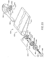
- FIG. 35 an exploded assembly view of end panel 16 shows that track 44 is received in a indentation 46 in end panel 16 and slider 40 is received in track 44.
- Track 44 includes two channels 48 and 50 which are configured to receive two flanges 52 and 54 of slider 40.
- the flanges 52 and 54 are coupled to a body 56 of slider 44.
- a pivot support 58 is also coupled to body 56 and includes a through-hole 60 configured to receive a support shaft 62 therethrough.
- Support shaft 62 is an elongated cylindrical shaft with a centerline which defines the pivot axis 42.
- Pivot support 58 includes a channel 64 formed in an upper surface 66.
- Channel 64 is perpendicular to and intersects through-hole 60.
- Pivot shaft 62 includes a through-hole 68 which has an axis 70 generally perpendicular to the longitudinal axis 42.
- Through-hole 68 is sized to receive a pin 72 therethrough.
- Pin 72 is an elongate cylindrical member with a diameter which is sized to be received in channel 64 when the pin 72 is aligned with channel 64.
- a rectangular portion of extender 18 is cut away along a side 74 to form a receiver 76 which is sized to receive the pivot support 58 of slider 44 with clearance between pivot support 58 and the extender 18.
- pivot shaft 62 is secured to extender 18 and moves with extender 18.
- the clearance between the extender 18 and pivot support 58 within receiver 76 allows extender 18 to be raised in the direction parallel to axis 42 such that pivot shaft 62 moves relative to pivot support 58 to allow pin 72 to clear channel 64. Once pin 72 clears channel 64, extender 18 is free to pivot relative to slide 40.
- Barrier 18 is supported on pin 72 which is supported on surface 66 of pivot support 58 when extender is not in the position shown in Fig. 3 .
- Pivot shaft 62, pin 72, and channel 64 of pivot support 58 cooperate as a detent assembly for positioning and holding the extender 18 in the use position shown in Fig. 3 until the extender is released by lifting the extender 18 to disengage pin 72 from channel 64.
- Slide 40 is retained within track 44 by two pins 78 and 80 which are coupled to body 16 within indentation 46 as shown in Fig. 36 .
- Pins 78 and 80 extend from a surface 82 of indentation 46 to engage a surface 84 (best seen in Fig. 37 ) of slide 40.
- extender 18 engages an end surface 86 of body 16 and surface 84 of slide 40 engages pins 78 and 80 which limits movement of slide 40 relative to track 44.
- an end panel 112 positioned on frame 14 includes three webs 88, 90 and 92 which extend from three spring retractors 94, 96, and 98 respectively as shown in Figs. 4 and 5 .
- the webs 88, 90 and 92 each couple to a frame 100.
- Frame 100 is coupled to a hook 102 which is configured to engage an upright 104 of siderail 36.
- Webs 88, 90 and 92 cooperate to form a barrier extending from a body 106 of end panel 112 to siderail 36 to provide boundary in the gap therebetween.
- Spring retractors 94, 96, and 98 allow webs 88, 90, and 92 to extend and retract as the size of the gap changes due to articulation of portions of the patient-support apparatus 110.
- frame 14 of patient-support apparatus 110 is extensible to change in length relative to other frames of the patient-support apparatus. As the length of frame 14 is changed, the distance between siderail 36 and end panel 112 changes. Webs 88, 90, and 92 lengthen or retract with the changes in the length of frame 14. Also, frame 14 is articulable between the position shown in Fig. 4 and a lowered position as suggested in Fig. 5 . To the extent that web 88 lengthens and web 92 shortens during this articulation, retractors 94 and 98 adjust the length of the webs 88 and 92 to react to those changes.
- FIG. 8 shows the end panel 212 mounted at a foot end of patient-support apparatus 210.
- End panel 212 further includes a left extender 218 and a right extender 220.
- left extender 218 is shown in an extended position wherein left extender 218 has been extended from body 216 to form a barrier along a left portion of the patient-support apparatus 210 to reduce the potential of a foot of a patient-supported on the patient-support apparatus 210 from slipping off from a mattress (not shown) on the patient-support apparatus 210.
- patient-support apparatus 210 has an extendable frame 214. Extenders 218 and 220 are movable to reduce the size of the gap between the end panel 212 and foot end siderails (not shown) of the patient-support apparatus 210.
- the extenders 218 and 220 are manually movable from a stowed position (e.g. extender 220) to an extended position (e.g. extender 218). Extenders 218 and 220 are engaged with body 216 and slidable relative thereto.
- the discussion of the structure of end panel 212 and the engagement and movement of extender 218 relative to body 216 is applicable to extender 220 except that extender 220 is positioned and configured to function on the right side of the patient-support apparatus 210.
- Body 216 includes a contoured surface 222 which intersects a generally planar vertical surface 224 positioned to face the head end of the patient-support apparatus 210.
- a slot 226 configured to receive a track 228 coupled to extender 218 such that slot 226 guides the movement of extender 218 relative to body 216.
- Slot 226 has a t-shaped cross-section with an upper flange 230 and a lower flange 232.
- Track 228 has a u-shaped upper guide 234 and a u-shaped lower guide 236 which engage with flanges 230 and 232 respectively. Engagement of flanges 230 and 232 with guides 234 and 236 supports extender 218 for movement relative to body 216.
- Body 216 includes a stop (not shown) which engages a flange (not shown) coupled to track 228 to limit the movement of extender 218 relative to body 216.
- Extender 218 has a contoured shape which is complementary to the contour of surface 222 such that extender 218 maintains a generally constant relative spacing with respect to body 216 during movement of extender 218.
- Extender 218 further includes a handle 242 which is includes a grip 238 and an aperture 240 through extender 218.
- Handle 242 is configured to be used by a user, such as a caregiver, for example, to be gripped to move extender 218 relative to body 216.
- Guides 234 and 236 a configured to have sufficient clearance such that extender 218 moves with minimal resistance.
- Extender 218 further comprises a generally planar flange 244 which extends away from end panel 212 generally toward the head end of patient-support apparatus 210.
- Flange 244 is configured to extend beneath a mattress supported on patient-support apparatus 210 to prevent linens on the mattress from becoming entangled with the movement of extender 218.
- the increase in coverage of extender 218 is depicted by the distance 246 which represents the change in length of extender 218 in the extended position as compared to extender 220 which is depicted in a retracted position in Figs. 7 and 8 .
- a extender 318 engages with a body 316 in a manner similar to the illustrative embodiment of Figs. 7 and 8 .
- End panel 312 further includes an engagement pin 322 coupled to a lower portion of extender 318.
- Engagement pin 322 is configured to be received by a coupler 324 secured on a frame 314 of a patient-support apparatus 310 shown in Figs. 10-12 .
- End panel 312 is supported on a moving portion 326 of frame 314 and coupler 324 is secured to a fixed portion 328. When frame 314 is extended, the movement of moving portion 326 relative to fixed portion 328 causes relative movement of extender 318 relative to body 316 of end panel 312.
- extender 318 extends to form a boundary in the space created between a siderail 36 and end panel 312. Having extender 318 secured to fixed portion 328 eliminates the need for a caregiver to manually extend the extender 318 when the length of frame 314 is increased.
- extender 318 Movement of moving portion 326 relative to fixed portion 328 between a retracted position shown in Fig. 10 and an extended position shown in Fig. 11 automatically extends and retracts extenders 318 and 320.
- the structure of extender 318 will be described in more detail below. It should be understood that the structure of extender 320 is similar with extender 320 positioned on the opposite side of end panel 312 such that extender 320 is a right-side version of left-side extender 318.
- Extender 318 comprises a first portion 330 and a second portion 332.
- First portion 330 is structured similar to extender 218 but includes the engagement pin 322.
- Second portion 332 is engaged with first portion 330 and movable relative thereto to extend away from first portion 330 and body 316.
- Second portion 332 includes a panel 334 and a grip 336 coupled to panel 334.
- Panel 334 and grip 336 cooperate to form a handle 338 which is configured to be grasped by a user to extend second portion 332 relative to first portion 330.
- engagement pin 322 may be omitted and the handle 338 may be used to extend second portion 332 and first portion 330.
- first portion 330 when the extender 318 is in a retracted position similar to the position of extender 320 in Fig. 9 , pulling on second portion 332 will extend second portion 332 relative to first portion 330. Once second portion 332 has been fully extended, additional pulling on handle 338 will extend first portion 330 relative to body 316. When handle 338 is pushed toward body 316, second portion 332 will move toward a retracted position until fully retracted and then additional pushing will tend to cause first portion 330 to retract relative to body 316. Referring to Fig. 9 , the direction of pull/extension is depicted by arrow 342 and the direction of push/retraction is depicted by arrow 344.
- First portion 330 comprises two mating panels 350 and 352.
- Panel 350 includes a guide 354 formed on an inner surface 356.
- Panel 352 includes a guide 358 formed on an inner surface 360.
- Guide 358 includes a channel 362 configured to receive a tab 348 ( Fig. 15 ).
- Guide 354 includes a channel 364 configured to receive a tab 340.
- panels 350 and 352 When panels 350 and 352 are coupled, an opening is formed to permit second portion 332 extend relative to first portion 330.
- panels 350 and 352 are glued together to form first portion 330.
- panels 350 and 352 may be secured to one another by a fastener, welding, heat staking or other mechanical process.
- second portion 332 is securable to a siderail 360 of patient-support apparatus 310 by a bracket 362.
- Bracket 362 includes a body 364 and two arms 366 and 368 which are configured to engage the grip 336 of second portion 332. Bracket 362 maintains second portion 332 in an extended position such that the gap between siderail 360 and body 316 of end panel 312 is fully enclosed by extender 318.
- Engagement pin 322 is received in coupler 324 such that first portion 330 extends and retracts with the extension and retraction of moving portion 326 of frame 314 relative to fixed portion 328.
- Bracket 362 illustratively includes an outer body portion 370 and an inner body portion 372 which are coupled to form body 364 as suggested in Figs. 28 and 29 .
- Body portions 370 and 372 are secured by a snap-fit between portions thereof.
- body portion 372 is formed to include a stud 374 which includes a cylindrical shaft 376 and an annular flange 378 formed at an end 380 of stud 374.
- Body portion 370 includes a cylindrical through-hole 382 with an annular surface 384 which is generally perpendicular to an axis 386 of through-hole 382.
- Through-hole 382 is sized such that flange 378 deflects when inserted into through-hole 382.
- flange 378 passes through through-hole 382 until flange 378 is received in a cavity 390 formed in an outer surface 392 of body portion 370.
- flange 378 expands and a surface 388 of flange 378 is engaged with surface 384 such that body portions 370 and 372 are secured together.
- Bracket 362 further includes a clamp 392 which includes arms 366 and 368 which are each coupled to a base 394 and extend therefrom. Each arm 366, 368 has a leg 396 and a hook 398 which extends away from leg 396 toward the opposite arm 366 or 368. Grip 336 of second portion 332 is sized to be received to between arms 366 and 368 such that the hooks 398, 398 extend around grip 336 to retain second portion 332 on bracket 362.
- Clamp 392 is formed such that arms 366 and 368 deflect to permit grip 336 to be inserted between arms 366 and 368. Arms 366 and 368 comprise an elastic material.
- arms 366 and 368 deflect to permit insertion of grip 336 and the arms 366 and 368 return to their natural shape such that they have sufficient strength to retain second portion 332 until a force is applied by a user to release grip 336.
- Clamp 392 is secured to flange 372 by two tabs 442 and 444 which are sized to be received in two slots 446 and 448 formed in flange 372.
- Base 394 is received by a cavity 452 formed in a generally planar surface 450 of flange 372.
- Cavity 452 includes a surface 454 which is generally planar a parallel to surface 450.
- Slots 446 and 448 are formed in surface 450.
- Tab 442 is formed to include a surface 456. When tab 442 is inserted into slot 452, surface 456 snaps over a surface (not shown) on flange 372.
- tab 444 is formed to include a surface 458 which snaps over a surface (not shown) when tab 444 is inserted slot 448.
- clamp 392 is positioned such that it is not centered on axis 386. This permits tabs 442 and 444 to be inserted through a wall of flange 372 and clear the rib 460 of flange 372.
- a bracket 400 in another embodiment, includes a clamp 402 having two arms 404 and 406 which move relative to one another to open clamp 402. Bracket 400 also includes a body 408 which is configured to be received in a siderail.
- Bracket 400 also includes a body 408 which is configured to be received in a siderail.
- bracket 362 may be omitted and replaced with bracket 400.
- Body 408 is an annular structure having two flanges 410 and 412.
- Body 408 comprises an elastic material which allows flange 410 or 412 to be deflected such that body 408 may be inserted into a siderail by user. For example, body 408 may be inserted in siderail 360.
- Siderail 360 is formed to include an elongate aperture 414 bounded about a perimeter by a convex semicircular surface 416.
- Aperture 414 is sized such that a gap 418 that separates opposing portions of surface 416 allows body 408 to be inserted into gap 418 by deflecting flange 410 or 412.
- Body 408 includes a concave semicircular surface 420 which is sized to engage surface 416 of siderail 360. Thus, body 408 is configured to be snapped into aperture 414 to secure bracket 400 to siderail 360.
- Bracket 400 further includes an actuator 422 which, when depressed, causes arms 404 and 406 to open to release clamp 402.
- actuator 422 When actuator 422 is depressed, clamp 402 opens to receive grip 336 of second portion 332. Once the grip 336 is positioned in the clamp 402, releasing actuator 422 causes clamp 402 to close such that arms 404 and 406 engage grip 336 and secure second portion 332 to siderail 360.
- actuator 422 is biased by a compression spring 424 which also acts on arms 404 and 406 to close clamp 402.
- Actuator 422 includes an annular flange 426 which engages an annular surface 428 of body 408 that retains actuator 422 within body 408.
- Actuator 422 further includes an annular channel 430.
- Arms 404 and 406 have the same geometry including a grip 432, a leg 434 coupled to the grip 432, and a pivot arm 436 coupled to leg 434 and extending generally perpendicular to leg 434. Pivot arm 436 engages with annular channel 430 of actuator 422.
- Arms 404 and 406 further include a through-hole 438 that is configured to engage a pivot pin 440 about which arm 404 or 406 pivots to open or close clamp 402.
- Body 408 is formed to define a cylindrical spring housing 442 in which spring 424 is positioned when bracket 400 is assembled.
- spring 424 urges actuator 422 into contact with surface 428 of body 408.
- pivot arms 436, 436 are in a neutral position such that arms 404 and 406 of clamp 402 are closed about grip 336 to secure second portion 332 to siderail 360.
- actuator 422 is depressed as shown in Fig. 27
- pivot arms 436, 436 are urged downwardly such that arms 404 and 406 pivot about pivot pins 440, 440 to open arms 404 and 406 such that grips 432, 432 release grip 336 of second portion 332.
- Spring 424 biases clamp 402 such that when actuator 422 is released, arms 404 and 406 of clamp 402 return to the closed position of Fig. 26 .
- bracket 400 is interchangeable with bracket 362.
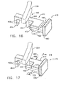
- a support 462 includes a mount 464 and an extension 466 coupled to mount 464.
- Two through-holes 468 are formed in mount 464 and configured to receive fasteners (not shown) to secure mount 464 of support 462 to fixed portion 328.
- Support 462 further includes a slide frame 470 coupled to extension 466.
- Slide frame 470 includes a main portion 472, a guide 474 coupled to main portion 472 and extending vertically downwardly therefrom, and a slide base 476 coupled to guide 474 and vertically spaced from main portion 472.
- Guide 474 is narrower than main portion 472 and slide base 476 such that slide frame 470 is generally I-shaped.
- a slider 478 is configured to engage slide frame 470 and be supported thereon.
- Slider 478 includes a handle 480 and a slide member 486 coupled to handle 480 and extending therefrom.
- Slide member 486 includes a frame 484 and a leg 482 which is spaced apart from frame 484 by a gap 492. The spacing of gap 492 between frame 484 and leg 482 is sized to receive guide 474 of slide frame 470.
- Slider 478 engages with slide frame 470 and is supported thereon. Movement of slider 478 between the position shown in Fig. 16 and the position shown in Fig. 17 results in engagement pin 322 being positioned in gap 492 and leg 484 retaining engagement pin 322. Engagement pin 322 is secured to fixed portion 328 in the position of Fig. 17 and is free to move relative to fixed portion 328 when slider 478 is in the position of Fig. 16 .
- Slider 478 is biased to the position shown in Fig. 17 by a spring 488 which is received in a cavity 490 formed in frame 484 and a cavity 494 formed in extension 466 of slide frame 462.
- spring 488 is compressed between a surface 496 of cavity 490 and a surface 498 (see Fig. 19 ) of cavity 494.
- Release of slider 478 results in spring 488 biasing slider 478 to the position of Fig. 17 such that handle 480 engages main portion 472 and slide base 476 of support 462.
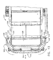
- an end panel 512 is supported on a frame 514 as shown in Figs. 13 and 23 .
- Frame 514 includes a fixed portion 528 and a moving portion 526 which is movable relative to fixed portion 528 to extend frame 514.
- Fixed portion 528 includes two couplers 522 and 524.
- End panel 512 includes two extenders 518 and 520 similar to the extenders 218 and 220 of the embodiment of Figs. 7 and 8 .
- Extenders are coupled to a main portion 216 which was described in detail in the discussion of the illustrative embodiment of Figs. 7 and 8 .
- Extenders 518 and 520 are engaged with main portion 216 as described with reference to extenders 218 and 220 above.
- extenders 518 and 520 further include two engagement pins (not shown) that are received in couplers 522 and 524 respectively when end panel 512 is positioned on frame 514.
- couplers 522 and 524 are not configured to release extenders 518 and 520.
- Extenders 518 and 520 are configured to always extend and retract with movement of moving portion 526 relative to fixed portion 528.
- couplers 522 and 524 are coupled to the bottom of fixed frame 528 by a base 530.
- a leg 532 is coupled to and extends vertically from base 530.
- a receiver 534 is coupled to leg 532 and extends generally horizontally outwardly from frame 514.
- An aperture 536 formed in receiver 534 is configured to receive the engagement pin of the extender 518 or 520.
- couplers 522 and 524 of the illustrative embodiment of Figs. 13 and 23 extend from beneath fixed portion 528, it should be understood that a coupler may be positioned in any of a number of positions on fixed portion 528. Also, couplers 324 and 522, 524 may be interchanged. In some embodiments, a coupler such as coupler 522 may be used in combination with bracket 362 or bracket 400. In some embodiments, bracket 362 or bracket 400 may be omitted and coupler 324 may be used alone. In some embodiments, an extender may have a first portion and a second portion which extends relative to the first portion, wherein the first portion does not include an engagement pin, but the second portion does couple to a bracket such as bracket 362 or bracket 400.
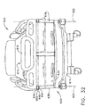
- an end panel 612 is coupled to a frame 614 of a patient-support apparatus 610 and includes two panels 618 and 620 which are each pivotable about a generally vertical axis as shown in Fig. 32 .
- Moving portion 618 is pivotable about an axis 622 and moving portion 620 is pivotable about an axis 624.
- each panel 618, 620 is pivotable about a generally horizontal axis between a first position wherein the panel 618 or 620 is in a generally vertical configuration as shown in solid in Figs. 31 and 32 , and second position wherein the panel 618 or 620 is in a generally horizontal configuration as shown in phantom.
- panels 618 and 620 may be positioned alongside a mattress 626 supported on patient-support apparatus 610 to form a barrier in the gap between siderails 628 and 630 respectively, and end panel 612.
- panels 618 and 620 may be positioned to serve as a shelf or a work surface for a caregiver.
- Panel 620 is pivotable about a generally horizontal axis 632 between the vertical configuration shown in solid and the horizontal configuration shown in phantom.
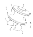
- Panel 620 comprises a body 634 supported on a positioner 636.
- the positioner 636 is adjustable to position the panel 620 about axis 624 and about axis 632.
- End panel 612 includes a support column 638 which supports a pivot shaft 640 which defines pivot axis 624.
- Positioner 636 includes a detent assembly 642 which maintains panel 620 in either the barrier position shown in Fig. 31 or in the stowed position shown in Fig. 32 .
- Detent assembly 642 includes a lower plate 644 and an upper plate 646.
- Lower plate 644 includes a tab 648 which is configured to engage a slot 652 in upper plate 646 to prevent movement of positioner 636 about axis 624.
- Lower plate 644 also includes a central through-hole 654 through which pivot shaft 640 passes.
- lower plate 644 includes two counter-sunk mount holes which receive two fasteners 656 which secure lower plate 644 to support column 638.
- Pivot shaft 640 is coupled to support column 638 and an upper portion 658 of a main portion 616 of end panel 612.
- Upper plate 646 includes two slots configured to engage tab 648 of lower plate 644. Slot 652 is positioned to engage tab 648 when panel 620 is in the stowed position of Fig. 32 .
- a second slot (not shown) is positioned approximately ninety degrees about axis 624 from slot 652. This second slot is positioned such that when positioner 636 is pivoted about axis 624, panel 620 is retained in the position shown in Fig. 31 .
- Panel 620 is pivoted about axis 624 until another slot engages tab 648.
- Positioner 636 further includes a coupler 660 which is coupled to upper plate 646 and pivotable about pivot shaft 640.
- axis 632 is pivotable about axis 624.
- Coupler 660 supports a shaft 662 on which body 634 of panel 620 is supported.
- Another detent assembly 664 is coupled to both body 634 and shaft 662 and is configured to maintain body 634 in any of a number of positions about axis 632.
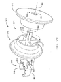
- Detent assembly 664 utilizes an adjustable locking hub similar to part number CL-100-ALH-S from Carr Lane Manufacturing Company, St. Louis, Missouri. Referring to Fig. 33 , a base 670 is received in body 634. Two springs 674, 674 are received in two of a plurality of blind holes 676 formed in base 670. Two locating pins 672, 672 are engaged with springs 674, 674 and received in the two holes 676 such that the spring 674 urges the locating pin 672 away from the base 670. A locator 678 is engaged with the base 670 and locating pins 672. Locator 678 includes a plurality of locating through-holes 680 positioned equally about a perimeter of locator 678.
- Locator 678 is received on a hub 682 of base 670 to position locator 678 such that through-holes 680 are positioned in alignment with locating pins 672.
- An actuator 684 is engaged with locator 678 such that a plurality of actuation pins 686 are received in through-holes 680.
- a bushing 692 is interposed between actuator 684 and locator 678 such that a fastener 690 engages bushing 692 and fastener 690 is tightened to secure base 670 to shaft 662.
- Bushing 692 retains actuator 684 in engagement with locating pins 672.
- actuator 684 is depressed such that actuation pins 686 over come the bias of springs 674 to disengage locating pins 672 from locator 678.
- Body 634 is then rotated to a new position. In the new position, actuator 684 is release and body 634 is pivoted to allow one or both locating pins 672 to engage through-holes 680 in locator 678.
- body 634 is postionable to a plurality of positions about axis 632.
- FIG. 30 Another embodiment of end panel 712 supported on a patient-support apparatus 710 shown in Fig. 30 is similar to end panel 612 in all respects with the exception that body 634 and positioner 636 are replaced with a body 734 and a positioner 736.
- Positioner 736 is similar to positioner 636 except that shaft 662 has been omitted and replaced with a shorter shaft (not shown).
- Body 734 includes a flange 738 which extends from a main portion 740.
- Flange 738 is coupled to detent assembly 664 and supported on the shorter shaft.
- the detent assembly 664 is positioned more closely to the main portion 616 of end panel 612 and therefore less likely to be inadvertently released by an occupant of the patient-support apparatus 710.
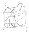
- end panel 812 includes two moving portions 818 and 820 as shown in Fig. 20 .
- Moving portion 818 is pivotable about a generally vertical axis 822 and moving portion 820 is pivotable about a generally vertical axis 824.
- Each of the moving portions 818 and 820 include a detent assembly 826.
- Detent assembly 826 is similar to detent assembly 642 of the illustrative embodiments of Figs. 31-33 and includes an upper plate 646 and a lower plate 644. With reference to moving portion 818 upper plate 646 is coupled to a body 828 of the moving portion 818.
- Lower plate 644 is coupled to a main portion 816 of end panel 812.
- Body 828 is movable along axis 822 when lifted to disengage a slot formed in upper plate 646 from the tab 648 to permit moving portion 818 to be pivoted about axis 822.
- Body 828 includes an aperture 830 formed therethrough and a handle 832. A user grips handle 832 or body 828 through aperture 830 to lift body 828 to disengage the detent assembly 826.
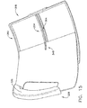
- a patient-support apparatus 910 includes a frame 914 and an end panel 912 mounted on frame 914 as shown in Fig. 21 .
- two pivot panels 918 and 920 are supported on frame 914 and each are pivotable about a generally vertical axis.
- a body 922 is coupled to a collar 924 which is positioned on a pivot shaft 926 coupled to frame 914 and which defines a pivot axis 930.
- Pivot panel 918 is pivotable about axis 930 and is configured to be pivoted to a position adjacent a mattress 928 supported on patient-support apparatus 910 as shown in Fig. 21 .
- pivot panel 918 engages a retainer 932 which maintains pivot panel 918 adjacent mattress 928 to act as a barrier in the gap between end panel 912 and a siderail (not shown) of patient-support apparatus 910.
- Pivot panel 918 is pivotable between the position shown in Fig. 21 and a stowed position wherein a surface 934 of pivot panel 918 engages a surface 936 of end panel 912. The friction between collar 924 and shaft 926 maintain pivot panel 918 in the stowed position until sufficient force is applied by a user to reposition the pivot panel 918.
- Pivot panel 920 is similar to pivot panel 918 with the exception that pivot panel 920 is a right side version and pivot panel 918 is a left side version.
Landscapes
- Health & Medical Sciences (AREA)
- Nursing (AREA)
- Life Sciences & Earth Sciences (AREA)
- Animal Behavior & Ethology (AREA)
- General Health & Medical Sciences (AREA)
- Public Health (AREA)
- Veterinary Medicine (AREA)
- Invalid Beds And Related Equipment (AREA)
Applications Claiming Priority (3)
| Application Number | Priority Date | Filing Date | Title |
|---|---|---|---|
| US77131806P | 2006-02-08 | 2006-02-08 | |
| EP07763571.2A EP1983865B1 (de) | 2006-02-08 | 2007-02-07 | Endplatte für patientenauflagevorrichtung |
| PCT/US2007/003311 WO2007092526A2 (en) | 2006-02-08 | 2007-02-07 | End panel for a patient-support apparatus |
Related Parent Applications (2)
| Application Number | Title | Priority Date | Filing Date |
|---|---|---|---|
| EP07763571.2A Division-Into EP1983865B1 (de) | 2006-02-08 | 2007-02-07 | Endplatte für patientenauflagevorrichtung |
| EP07763571.2 Division | 2007-02-07 |
Publications (1)
| Publication Number | Publication Date |
|---|---|
| EP2556811A1 true EP2556811A1 (de) | 2013-02-13 |
Family
ID=80784719
Family Applications (2)
| Application Number | Title | Priority Date | Filing Date |
|---|---|---|---|
| EP12188561A Withdrawn EP2556811A1 (de) | 2006-02-08 | 2007-02-07 | Endplatte für Patientenauflagevorrichtung |
| EP07763571.2A Active EP1983865B1 (de) | 2006-02-08 | 2007-02-07 | Endplatte für patientenauflagevorrichtung |
Family Applications After (1)
| Application Number | Title | Priority Date | Filing Date |
|---|---|---|---|
| EP07763571.2A Active EP1983865B1 (de) | 2006-02-08 | 2007-02-07 | Endplatte für patientenauflagevorrichtung |
Country Status (3)
| Country | Link |
|---|---|
| US (1) | US7934276B2 (de) |
| EP (2) | EP2556811A1 (de) |
| WO (1) | WO2007092526A2 (de) |
Families Citing this family (28)
| Publication number | Priority date | Publication date | Assignee | Title |
|---|---|---|---|---|
| EP2556811A1 (de) * | 2006-02-08 | 2013-02-13 | Hill-Rom Services, Inc. | Endplatte für Patientenauflagevorrichtung |
| US9510690B2 (en) | 2006-08-29 | 2016-12-06 | Ascion, Llc | Foam spring mattress configured with variable firmness |
| US20080093784A1 (en) * | 2006-08-29 | 2008-04-24 | Rawls-Meehan Martin B | Foam spring mattress configured with variable firmness |
| US8239986B2 (en) | 2008-03-13 | 2012-08-14 | Hill-Rom Services, Inc. | Siderail assembly for a patient-support apparatus |
| US8296884B2 (en) * | 2008-03-13 | 2012-10-30 | Hill-Rom Services, Inc. | Siderail gap filler |
| JP5051781B2 (ja) * | 2008-09-22 | 2012-10-17 | パラマウントベッド株式会社 | ベッドの差込式サイドレール装置 |
| JP5051780B2 (ja) * | 2008-09-22 | 2012-10-17 | パラマウントベッド株式会社 | ベッドの差込式サイドレール装置 |
| JP5164117B2 (ja) * | 2009-01-21 | 2013-03-13 | パラマウントベッド株式会社 | ベッドボード |
| US8474921B2 (en) * | 2009-10-02 | 2013-07-02 | Hill-Rom Services, Inc. | Wall-mounted patient egress and patient assist bar |
| US20120023659A1 (en) * | 2010-08-02 | 2012-02-02 | Zerhusen Robert M | Endboard assembly |
| US8637724B2 (en) | 2010-09-09 | 2014-01-28 | Basf Se | Process for the regeneration of a copper, zinc and zirconium oxide-comprising adsorption composition |
| US8381337B2 (en) * | 2010-10-29 | 2013-02-26 | Hill-Rom Services, Inc. | Egress assist footboard |
| US20120110741A1 (en) * | 2010-11-04 | 2012-05-10 | Mears Brian E | Wrap around foot panel |
| US8353071B2 (en) | 2010-12-01 | 2013-01-15 | Hill-Rom Services, Inc. | Removable integrated board and partial foot section |
| US8341778B2 (en) | 2011-02-07 | 2013-01-01 | Hill-Rom Services, Inc. | Bed gap filler and footboard pad |
| US20120246830A1 (en) * | 2011-03-31 | 2012-10-04 | Hornbach David W | Footboard egress design |
| USD656765S1 (en) * | 2011-05-02 | 2012-04-03 | Linet Spol. S.R.O. | Footboard |
| USD656764S1 (en) * | 2011-05-02 | 2012-04-03 | Linet Spol. S R.O. | Headboard |
| EP2644177A1 (de) * | 2012-03-29 | 2013-10-02 | Hill-Rom Services, Inc. | Fußbord-Ausstiegsentwurf |
| JP5420749B2 (ja) * | 2012-12-17 | 2014-02-19 | パラマウントベッド株式会社 | ベッドボード |
| AU2014239599B2 (en) | 2013-03-15 | 2018-08-09 | Stryker Corporation | Medical support apparatus |
| JP5922608B2 (ja) * | 2013-03-22 | 2016-05-24 | ジーイー・メディカル・システムズ・グローバル・テクノロジー・カンパニー・エルエルシー | 医療装置用テーブルおよび医療装置 |
| US10660809B2 (en) * | 2015-09-11 | 2020-05-26 | Stryker Corporation | Telescoping assembly for use on a patient support apparatus |
| US11628102B2 (en) | 2018-05-21 | 2023-04-18 | Hill-Rom Services, Inc. | Patient support apparatus adaptable to multiple modes of transport |
| USD1006517S1 (en) * | 2021-02-11 | 2023-12-05 | Linet Spol. S R.O. | Bed end |
| USD1005764S1 (en) * | 2021-02-11 | 2023-11-28 | Linet Spol. S R.O. | Side rail for bed |
| JP7406823B2 (ja) * | 2021-11-01 | 2023-12-28 | 株式会社プラッツ | ベッド |
| JP7098809B1 (ja) * | 2021-11-09 | 2022-07-11 | パラマウントベッド株式会社 | ベッドボードおよびベッド |
Citations (2)
| Publication number | Priority date | Publication date | Assignee | Title |
|---|---|---|---|---|
| US3048857A (en) * | 1961-05-01 | 1962-08-14 | Clyde B Hutt | Bed with adjustable side rail assembly |
| US6289539B1 (en) * | 1999-12-16 | 2001-09-18 | Erwin A. Alpern | Handrail attachments for beds |
Family Cites Families (243)
| Publication number | Priority date | Publication date | Assignee | Title |
|---|---|---|---|---|
| US2710976A (en) | 1955-06-21 | martensen | ||
| US1682394A (en) | 1928-08-28 | Charles c | ||
| US421656A (en) | 1890-02-18 | Removable siding for beds | ||
| US3097370A (en) * | 1963-07-16 | Four-way adjustable bed rail unit | ||
| US993119A (en) | 1910-04-22 | 1911-05-23 | Percival D Stannard | Footboard-quilt. |
| US1008168A (en) * | 1911-03-20 | 1911-11-07 | George Markus | Bedstead. |
| US1398203A (en) | 1921-02-19 | 1921-11-22 | Henry A Schmidt | Convertible bed-spring |
| US1885974A (en) | 1930-07-24 | 1932-11-01 | Winn John Albert | Sectional mattress |
| US2164484A (en) | 1937-03-10 | 1939-07-04 | Joseph A Wolfe | Detachable side panel for beds |
| US2136088A (en) | 1937-08-17 | 1938-11-08 | Frank A Hall & Sons | Bed attachment |
| US2254466A (en) | 1938-04-15 | 1941-09-02 | Albert Lisa | High-chair pad |
| US2281209A (en) | 1938-07-29 | 1942-04-28 | Smith Orville Dale | Combination bed and carriage |
| US2452366A (en) | 1944-08-11 | 1948-10-26 | Robert R Freund | Patient adjustable foot section for articulated beds |
| US2556591A (en) | 1946-02-06 | 1951-06-12 | Walter M Loxley | Invalid bed |
| US2587291A (en) | 1948-10-25 | 1952-02-26 | Rochers Jean B Des | Folding bed guard |
| US2605151A (en) | 1949-03-23 | 1952-07-29 | Shampaine Hyman Robert | Obstetrical and delivery operating table |
| US2564083A (en) | 1949-04-21 | 1951-08-14 | Alfred H W Stechert | Invalid's bed with manual control |
| US2722017A (en) | 1951-11-16 | 1955-11-01 | Hill Rom Co Inc | Side guards for hospital beds |
| US2766463A (en) | 1952-02-19 | 1956-10-16 | Bendersky Sadie | Means for converting a bed to a chair |
| US2817854A (en) | 1954-10-04 | 1957-12-31 | Edmond O Pratt | Guard attachment for beds |
| US2817855A (en) | 1955-04-08 | 1957-12-31 | Edmond O Pratt | Adjustable fence attachment for beds |
| US2869614A (en) | 1955-05-25 | 1959-01-20 | Floyd B Wamsley | Combination wheel chair and stretcher |
| US3010121A (en) | 1957-04-12 | 1961-11-28 | Roy Frederick Thompson | Adjustable support device |
| US2979738A (en) | 1958-07-02 | 1961-04-18 | Harold D Goldberg | Bed rail |
| US2951252A (en) | 1958-07-25 | 1960-09-06 | Harvard Mfg Company | Bedframe side rail end cap |
| US3021534A (en) | 1958-12-24 | 1962-02-20 | Simmons Co | Adjustable bed rails |
| US3018492A (en) | 1959-04-22 | 1962-01-30 | Rosen Norman | Protective bumper device |
| US3053568A (en) | 1960-02-05 | 1962-09-11 | Clarence A Silva | Chair-bed combination |
| US3099440A (en) | 1960-09-26 | 1963-07-30 | Ritter Co Inc | Apparatus for controlling the flow of fluids |
| US3055020A (en) | 1961-02-10 | 1962-09-25 | Hard Mfg Co | Restraining structure for beds |
| US3138805A (en) | 1961-04-11 | 1964-06-30 | Salvatore J Piazza | Bed-wheelchair |
| US3233255A (en) | 1961-05-22 | 1966-02-08 | Miller Herman Inc | Bed construction |
| US3112500A (en) | 1961-05-24 | 1963-12-03 | Benjamin R F Macdonald | Hospital bed |
| US3210779A (en) | 1961-09-11 | 1965-10-12 | Ted E Herbold | Multiple position combination chair-bed |
| US3148387A (en) | 1961-09-14 | 1964-09-15 | Jr Michael C Sarnie | Support attachment for sleeping surfaces |
| US3239853A (en) | 1962-01-15 | 1966-03-15 | Benjamin R F Macdonald | Convertible hospital bed-chair |
| US3195151A (en) | 1962-02-23 | 1965-07-20 | Russell I Boyer | Hospital bed footboard and clamp therefor |
| DK116534B (da) | 1962-08-23 | 1970-01-19 | A Michelsen | Sidde- og liggemøbel, især ottoman med magasinryg. |
| US3309717A (en) | 1963-03-20 | 1967-03-21 | American Seating Co | Hospital bed |
| US3262133A (en) | 1963-08-01 | 1966-07-26 | Lite Hospital Equipment Inc | Adjustable bed |
| US3220022A (en) | 1963-12-23 | 1965-11-30 | Nelson Ted | Hospital bed sliding foot section |
| US3220021A (en) | 1964-04-09 | 1965-11-30 | Nelson Ted | Adjustable seat length hospital bed |
| US3249387A (en) | 1965-02-16 | 1966-05-03 | Mobilaid Inc | Swinging arm rest |
| US3266545A (en) | 1965-04-28 | 1966-08-16 | Dentin Mfg Co | Stadium bench cover |
| FR1450817A (fr) | 1965-07-16 | 1966-06-24 | Le Lit Tous Soins | Grille amovible pour lits médicaux |
| SE300672B (de) | 1965-09-02 | 1968-05-06 | Redev Ab | |
| CA795223A (en) | 1966-04-11 | 1968-09-24 | M. Tabler John | Baby mattress with attached side pads |
| US3384147A (en) * | 1966-04-13 | 1968-05-21 | Richard D. Smith | Electrically adjustable venetian blind structure |
| US3351962A (en) | 1966-07-01 | 1967-11-14 | Bedline Inc | Adjustable guard frame for beds |
| US3344445A (en) | 1966-08-12 | 1967-10-03 | Institutional Ind Inc | Side panel construction for stretcher-beds |
| US3456269A (en) | 1967-10-16 | 1969-07-22 | Robert Goodman | Foldable bed with adjustable contour bed spring |
| US3486176A (en) | 1967-11-16 | 1969-12-30 | Lumex | Safety and patient assist device |
| GB1286252A (en) | 1968-08-29 | 1972-08-23 | Nat Dev Corp | Safety sides for beds |
| AU430169B2 (en) | 1968-10-11 | 1972-11-15 | Hodge Investments Proprietary Limited' | Invalid chair |
| US3593350A (en) | 1969-03-13 | 1971-07-20 | Dominion Metalware Ind Ltd The | Retractable bed |
| US3624847A (en) | 1969-04-30 | 1971-12-07 | Lumex | Adjustable bed rail unit |
| US3610685A (en) | 1969-07-01 | 1971-10-05 | Hamilton Cosco Inc | Backrest pad |
| US3585659A (en) | 1969-10-15 | 1971-06-22 | Hill Rom Co Inc | Safety side guard for hospital beds |
| US3619824A (en) | 1970-02-10 | 1971-11-16 | Bunny Bear Inc | Crib bumper |
| US3602929A (en) * | 1970-03-02 | 1971-09-07 | Lumex | Adjustable bed rail unit |
| US3905591A (en) | 1970-09-24 | 1975-09-16 | Siemens Ag | Patient{3 s couch |
| US3735432A (en) | 1971-01-06 | 1973-05-29 | B Kreten | Collapsible water mattress frame |
| US3742530A (en) | 1971-06-16 | 1973-07-03 | M Clark | Bedside rail cover |
| US3823428A (en) | 1972-04-13 | 1974-07-16 | Standard Int Corp | Adjustable bed rails |
| US3851345A (en) | 1972-05-17 | 1974-12-03 | Interroyal Corp | Safety side mechanism |
| US3845511A (en) | 1972-08-10 | 1974-11-05 | Interroyal Corp | Universal headboard construction |
| NL7401831A (de) | 1973-02-14 | 1974-08-16 | ||
| US3897973A (en) | 1973-06-05 | 1975-08-05 | Amerco Inc | Blood drawing chair |
| US3865434A (en) | 1973-07-20 | 1975-02-11 | Everest & Jennings | Rotating wheelchair arm |
| US3893197A (en) | 1974-02-11 | 1975-07-08 | Maurine E Ricke | Hospital bed footboard assembly |
| US3877090A (en) | 1974-04-12 | 1975-04-15 | Fine Art Pillow And Spec Corp | Crib bumper and mattress |
| US3932903A (en) | 1974-10-04 | 1976-01-20 | Hill-Rom Company, Inc. | Guard including electrical controls and slidable underneath the bed |
| GB1466080A (en) | 1974-10-30 | 1977-03-02 | Siddall Hilton Ltd | Hospital bed attachments |
| US3971083A (en) | 1974-11-27 | 1976-07-27 | Joerns Furniture Company | Side guard for beds |
| FR2302719A1 (fr) * | 1975-03-07 | 1976-10-01 | Nippon Felt Co Ltd | Lit pour personne invalide ou malade |
| US3967334A (en) * | 1975-03-31 | 1976-07-06 | Ricke Maurine E | Hospital bed footboard assembly |
| US4258445A (en) | 1976-07-15 | 1981-03-31 | Zur Henry C | Beds and adjustable body supporting assemblies |
| US4127906A (en) | 1976-07-15 | 1978-12-05 | Zur Henry C | Adjustable bed-chair |
| US4106138A (en) | 1977-09-28 | 1978-08-15 | Simmons Company | Platform bed |
| US4139917A (en) * | 1977-10-17 | 1979-02-20 | Loel Fenwick | Labor, delivery and patient care bed |
| US4168099A (en) | 1978-03-27 | 1979-09-18 | Midmark Corporation | Multi-position examination chair |
| US4183015A (en) | 1978-06-26 | 1980-01-08 | Hill-Rom Company, Inc. | Side guard for bed including means for controlling remote electrical devices |
| US4186456A (en) | 1978-07-14 | 1980-02-05 | American Hospital Supply Corporation | Rail system for bed or stretcher |
| US4215446A (en) | 1978-08-28 | 1980-08-05 | Patsie Mahoney | Padded hospital bed siderail cover |
| US4240169A (en) | 1979-01-26 | 1980-12-23 | Roos Kjell E | Patient transferring apparatus |
| NL7901576A (nl) | 1979-02-28 | 1980-09-01 | Philips Nv | Patieentendrager met onderling kantelbare draagorganen. |
| US4232415A (en) | 1979-03-19 | 1980-11-11 | Webber Gloria C | Mattress sling |
| US4214326A (en) | 1979-05-31 | 1980-07-29 | Spann Donald C | Body positioner and protection apparatus |
| US4336621A (en) | 1980-02-25 | 1982-06-29 | Schwartz Donald R | Disposable orthopedic overmattress for articulated beds |
| US4332042A (en) | 1980-03-31 | 1982-06-01 | Burlington Industries, Inc. | Geriatric environmental systeming |
| US4370765A (en) | 1980-09-05 | 1983-02-01 | Webber Gloria C | Envelope for a bed having side rails |
| US4439880A (en) | 1980-09-18 | 1984-04-03 | Burlington Industries, Inc. | Geriatric bed construction with sideguards |
| US4409695A (en) | 1981-02-03 | 1983-10-18 | Burke, Inc. | Adjustable bed for morbidly obese patients |
| US4453732A (en) | 1981-12-24 | 1984-06-12 | Assanah Albert A | Patient transport and care vehicle |
| FR2523437A1 (fr) | 1982-03-18 | 1983-09-23 | Idetec Entreprise | Lit medical |
| USD276112S (en) | 1982-06-10 | 1984-10-30 | Ferrell Linda S | Hospital bed protective device |
| US4491993A (en) | 1982-12-15 | 1985-01-08 | Santo Philip J | Mechanism for maintaining the shape of a floatation sleep system |
| NL8300814A (nl) | 1983-03-04 | 1984-10-01 | Avek B V Matrassen En Ledikant | Matras bestaande uit een combinatie van luchtkamer, schuimrand en afritsbare hoes. |
| US4484367A (en) | 1983-04-08 | 1984-11-27 | Jenkins Betty S | Nurse call apparatus |
| WO1985000745A1 (en) | 1983-08-17 | 1985-02-28 | Idéo Ab | A chair and/or bed arrangement |
| US4612679A (en) | 1984-03-01 | 1986-09-23 | Amedco Health Care Inc. | Bed side guard assembly |
| US4676687A (en) | 1984-03-09 | 1987-06-30 | Henry Koffler | Universal bedside rail clamp |
| GB8422275D0 (en) | 1984-09-04 | 1984-10-10 | Fw Equipment Co Ltd | Body support |
| US4607402A (en) | 1985-04-15 | 1986-08-26 | Pollard Dianne J | Retainer sheet |
| US4873734A (en) | 1985-04-15 | 1989-10-17 | Pollard Dianne J | Bumper sheet |
| US4776047A (en) | 1985-05-07 | 1988-10-11 | Med Bed Technologies, Inc. | Multiple function invalid bed arrangement |
| US4685159A (en) | 1985-05-09 | 1987-08-11 | Hans Oetiker | Hospital bed |
| US4839933A (en) | 1985-08-13 | 1989-06-20 | Plewright William B | Patient transfer and conveying vehicle |
| US4768249A (en) | 1985-12-30 | 1988-09-06 | Ssi Medical Services, Inc. | Patient support structure |
| US4745647A (en) | 1985-12-30 | 1988-05-24 | Ssi Medical Services, Inc. | Patient support structure |
| US4672698A (en) | 1986-02-07 | 1987-06-16 | Sands Donald F | Bed rail cushion system |
| US4670923A (en) | 1986-03-17 | 1987-06-09 | Gabriel Janice Y | Transparent crib bumper pads |
| US4653129A (en) | 1986-04-25 | 1987-03-31 | Midmark Corporation | Side rail assembly for a wheeled stretcher |
| US4704750A (en) | 1986-07-07 | 1987-11-10 | Wheelock Barry E | Assembleable, free-standing, bed suspension apparatus |
| US4747171A (en) | 1986-08-12 | 1988-05-31 | Simmons Healthcare, Inc. | Hospital bed rail assembly |
| US4941221A (en) | 1986-08-15 | 1990-07-17 | Ian Donald Butcher | Body supporting apparatus |
| US4800600A (en) | 1986-08-20 | 1989-01-31 | Baum Marilyn J | Decorative crib bumper |
| US4799277A (en) | 1986-08-25 | 1989-01-24 | American-National Watermattress Corporation | Hybrid watermattress having concave softsides |
| US4757564A (en) | 1986-08-25 | 1988-07-19 | American-National Watermattress Corporation | Mattress having cover with memory fabric |
| YU46743B (sh) | 1986-12-02 | 1994-04-05 | Milenko Pupović | Krevet sa podešljivim položajima |
| US4710049A (en) | 1987-01-30 | 1987-12-01 | Virco Mfg. Corporation | Safety hinge |
| US4751754A (en) | 1987-04-02 | 1988-06-21 | Hill-Rom Company, Inc. | Dual hydraulic hospital bed with emergency bypass circuit |
| US4710992A (en) | 1987-05-01 | 1987-12-08 | Falwell Bobby R | Waterbed rail cap |
| US4862530A (en) | 1987-07-27 | 1989-09-05 | Chen Chung C | Convertible bed |
| US4783864A (en) | 1987-08-03 | 1988-11-15 | Turner Ronald L | Producing subconscious integumental reflex action to keep children away from guard rail while sleeping on bunk bed |
| US4974905A (en) | 1987-08-10 | 1990-12-04 | Davis John W | Chair bed |
| US4767419A (en) | 1987-09-28 | 1988-08-30 | Fattore Mary E | Protective pad for crib rail |
| IL85442A (en) | 1988-02-17 | 1992-11-15 | Oded Sheinfeld | Combined bed and relaxation chair |
| US4827545A (en) | 1988-03-09 | 1989-05-09 | Arp Norman T | Removable protective covering assembly for a bed restraining side rail |
| US4858260A (en) | 1988-03-11 | 1989-08-22 | Hausted, Inc. | Patient transport apparatus including Trendelenburg mechanism and guard rail |
| RU2128479C1 (ru) | 1988-03-23 | 1999-04-10 | Хилл-Ром, Инк. | Устройство для поддержания пациента (варианты) и способ поддержания тела человека на матраце |
| US5111542A (en) | 1988-04-04 | 1992-05-12 | Farley David L | Anatomically conformable foam support pad |
| US4872228A (en) | 1988-06-27 | 1989-10-10 | Bishop Carolyn B | Bed guard |
| US4862529A (en) | 1988-07-13 | 1989-09-05 | Hill-Rom Company, Inc. | Hospital bed convertible to chair |
| US4894876A (en) | 1988-07-15 | 1990-01-23 | Hill-Rom Company, Inc. | Multipurpose maternity care bed |
| US4998310A (en) | 1988-10-12 | 1991-03-12 | Olson Robert V | Breakdown air mattress assembly |
| US5216768A (en) | 1988-11-17 | 1993-06-08 | Oliver H. Bodine, Jr. | Bed system |
| US4901383A (en) | 1989-03-09 | 1990-02-20 | Alex Yang | Modular frame for a water bed |
| US5010611A (en) | 1989-06-07 | 1991-04-30 | Sarah Mallett | Fitted safety crib sheet with integral bumper liner |
| EP0714649A2 (de) | 1989-06-26 | 1996-06-05 | IURA, Tadashi | Bett |
| US5077843A (en) | 1990-07-28 | 1992-01-07 | Hill-Rom Company, Inc. | Hospital bed and assemblies of hospital care apparatus |
| US5083332A (en) | 1989-07-28 | 1992-01-28 | Hill-Rom Company, Inc. | Hospital bed with collapsible side edges and laterally-movable side guards |
| US4985946A (en) | 1989-07-28 | 1991-01-22 | Hill-Rom Company, Inc. | Hospital bed adapted for use with a C-arm |
| US5179744A (en) | 1989-07-28 | 1993-01-19 | Hill-Rom Company, Inc. | Hospital bed with inflatable and collapsible side edges and laterally-movable side guards |
| US4991244A (en) | 1990-01-05 | 1991-02-12 | Walker Robert A | Border for air bed |
| US4993089A (en) | 1990-03-21 | 1991-02-19 | Amfab, Incorporated, Division Of Bissell, Inc. | Bed rail mechanism |
| US5577279A (en) | 1990-05-16 | 1996-11-26 | Hill-Rom Company, Inc. | Hospital bed |
| US5479666A (en) | 1994-01-25 | 1996-01-02 | Hill-Rom Company, Inc. | Foot egress chair bed |
| US5454126A (en) | 1994-01-25 | 1995-10-03 | Hill-Rom Company, Inc. | Foot egress chair bed |
| US5040253A (en) | 1990-07-16 | 1991-08-20 | Cheng Yen Feng | Variable bed having multiple functions |
| US5035014A (en) | 1990-08-10 | 1991-07-30 | Ssi Medical Services, Inc. | Comfort guard for low air loss patient support systems |
| US5083334A (en) | 1990-10-12 | 1992-01-28 | Ssi Medical Services, Inc. | Side guard for patient support |
| US5060327A (en) | 1990-10-18 | 1991-10-29 | Hill-Rom Company, Inc. | Labor grips for birthing bed |
| GB2250189B (en) | 1990-11-28 | 1993-11-24 | Nesbit Evans & Co Ltd | Beds |
| US5129117A (en) | 1990-11-28 | 1992-07-14 | Hill-Rom Company, Inc. | Birth assist protection guard |
| USD336577S (en) | 1990-12-17 | 1993-06-22 | Hill-Rom Company, Inc. | Sideguard for a birthing bed |
| US5044025A (en) | 1991-02-08 | 1991-09-03 | Hunsinger Charles J | Safety device for beds with side rails |
| US5084925A (en) | 1991-02-19 | 1992-02-04 | Product Strategies, Inc. | Hospital bed guard extender |
| US5072463A (en) | 1991-04-11 | 1991-12-17 | Willis William J | EZ access bed |
| US5193633A (en) | 1991-06-07 | 1993-03-16 | Wright State University | Motorized transfer and transport system for the disabled |
| US5097550A (en) | 1991-06-17 | 1992-03-24 | Marra Jr John J | Cover for hospital bed rails |
| US5175897A (en) | 1991-06-17 | 1993-01-05 | Marra Jr John J | Cover for hospital bed rails |
| US5197156A (en) | 1991-07-31 | 1993-03-30 | Stryker Corporation | Transfer board support lever and support post |
| FR2680955B1 (fr) | 1991-09-06 | 1993-12-17 | Lecouviour Ets | Lit a barriere escamotable. |
| US5230113A (en) | 1992-04-14 | 1993-07-27 | Good Turn, Inc. | Multiple position adjustable day night patient bed chair |
| EP0574188B1 (de) | 1992-06-06 | 1997-04-02 | Mangar International Limited | Anhebevorrichtung |
| US5191663A (en) | 1992-07-02 | 1993-03-09 | Hill-Rom Company, Inc. | Hospital bed sideguard pads |
| US5384927A (en) | 1993-01-27 | 1995-01-31 | Canadian Aging & Rehabilitation Product Development Corp. | Security rail attachment for a bed |
| US5381571A (en) | 1993-04-13 | 1995-01-17 | Gabhart; Thomas S. | Pivotable and lockable hospital bed guard |
| US5365623A (en) | 1993-08-27 | 1994-11-22 | Springer Maurice D | Telephone holder for bed side rail |
| US5530974A (en) | 1993-08-30 | 1996-07-02 | Demar Technologies, Inc. | Patient repositioning and position maintenance device |
| US5410765A (en) | 1993-11-24 | 1995-05-02 | Youngblood; Kevin | Crib bumper pad |
| GB9324397D0 (en) | 1993-11-27 | 1994-01-12 | Ferris Trevor R | Pivoting safety rail for a bed |
| US5715548A (en) | 1994-01-25 | 1998-02-10 | Hill-Rom, Inc. | Chair bed |
| US5636397A (en) | 1994-03-01 | 1997-06-10 | Boyd; Terence J. | Futon mattress |
| US5537701A (en) | 1994-03-15 | 1996-07-23 | Maxwell Products, Inc. | Adjustable articulated bed |
| US5481772A (en) | 1994-03-24 | 1996-01-09 | Glynn; William D. | Bed rail apparatus |
| US5421046A (en) | 1994-05-04 | 1995-06-06 | Vande Streek; Janet L. | Bed bumper pad |
| US5524306A (en) | 1994-05-20 | 1996-06-11 | Morales, George Hector | Bed restraint |
| US5455973A (en) | 1994-05-23 | 1995-10-10 | Brumfield; Barbara A. | Cushion cover with adjustable peripheral sideguard |
| US5450641A (en) | 1994-06-21 | 1995-09-19 | Connecticut Artcraft Corp | Inflatable bed rail guard |
| US5575025A (en) | 1994-11-14 | 1996-11-19 | Peters; Michael J. | Gurney with protective cover |
| US6212714B1 (en) * | 1995-01-03 | 2001-04-10 | Hill-Rom, Inc. | Hospital bed and mattress having a retracting foot section |
| US5557813A (en) | 1995-03-03 | 1996-09-24 | Simmons Company | Knock down mattress system |
| US5577277A (en) | 1995-03-30 | 1996-11-26 | Safety 1St, Inc. | Collapsable bed side rail |
| US5542135A (en) | 1995-05-15 | 1996-08-06 | Safe Surroundings, Inc. | Self-retaining bumper pad |
| US5537699A (en) | 1995-05-22 | 1996-07-23 | Foamex L.P. | Mattress border assembly and method of making same |
| US5678267A (en) | 1995-07-11 | 1997-10-21 | Kinder; Florence E. | Medical examination table handle system |
| US5557817A (en) | 1995-07-14 | 1996-09-24 | Haddock; Henry J. | Protective cover for hospital bed rails |
| US5630238A (en) | 1995-08-04 | 1997-05-20 | Hill-Rom, Inc. | Bed with a plurality of air therapy devices, having control modules and an electrical communication network |
| US5732423A (en) | 1995-08-04 | 1998-03-31 | Hill-Rom, Inc. | Bed side rails |
| US5926873A (en) | 1995-08-21 | 1999-07-27 | Fountain; Irene | Crib railing guard |
| US5642546A (en) | 1995-09-19 | 1997-07-01 | Select Comfort Corporation | Inflatable mattress with improved border support wall |
| US5802646A (en) | 1995-11-30 | 1998-09-08 | Hill-Rom, Inc. | Mattress structure having a foam mattress core |
| DE59501790D1 (de) | 1995-12-18 | 1998-05-07 | Le Couviour S A | Bettseitenteil |
| US5701623A (en) | 1996-03-11 | 1997-12-30 | Latex Foam Products, Inc. | Composite mattress and mattress topper having a latex foam core |
| US5642545A (en) | 1996-05-13 | 1997-07-01 | Howard; Bridget | Fitted crib pads adapted to cover horizontal and vertical rails |
| US5781945A (en) | 1996-05-20 | 1998-07-21 | Brk Brands, Inc. | Portable foldable bed rail |
| GB2313303B (en) | 1996-05-20 | 2000-04-12 | Egerton Hospital Equip | Improvements in and relating to beds |
| US5794288A (en) | 1996-06-14 | 1998-08-18 | Hill-Rom, Inc. | Pressure control assembly for an air mattress |
| US5699570A (en) | 1996-06-14 | 1997-12-23 | Span-America Medical Systems, Inc. | Pressure relief valve vent line mattress system and method |
| CA2181021C (en) | 1996-07-11 | 2007-10-02 | Eric Laganiere | Split side guards |
| US5704085A (en) | 1996-07-19 | 1998-01-06 | Serta, Inc. | Edge support for a mattress |
| US5754998A (en) | 1996-08-19 | 1998-05-26 | Selton; Daniel E. | Therapeutic bedding pad |
| US5960497A (en) | 1997-08-22 | 1999-10-05 | Kci-Rik Acquisition, Corp. | Pressure relieving pad with graduated pillars |
| US5749112A (en) | 1996-09-30 | 1998-05-12 | Metzler; Donald L. | Invalid bed guard sheet |
| US5787532A (en) | 1996-10-04 | 1998-08-04 | The Ohio Mattress Company Licensing And Components Group | Internal mattress wall structures interlockingly engageable with mattress innerspring assemblies |
| US5771506A (en) | 1996-10-22 | 1998-06-30 | Joiner; Glenda P. | Protection apparatus |
| US5802636A (en) | 1996-11-12 | 1998-09-08 | Hill-Rom, Inc. | Integrated siderail and accessory rail for a bed |
| US5761756A (en) | 1996-10-25 | 1998-06-09 | The First Years Inc. | Portable bed rail |
| US5745939A (en) | 1996-11-12 | 1998-05-05 | Gaymar Industries, Inc. | Leg rest |
| US5671490A (en) | 1996-11-13 | 1997-09-30 | Wu; Sung-Tsun | Collapsible bed rail structure |
| US5878452A (en) | 1996-12-03 | 1999-03-09 | Hill-Rom, Inc. | Long term care bed controls |
| US6089593A (en) | 1997-02-10 | 2000-07-18 | Hill-Rom, Inc. | Ambulatory care chair |
| US6249924B1 (en) | 1997-02-14 | 2001-06-26 | Earl Sanderson Kluft | Anti-roll off mattress construction |
| US6058531A (en) | 1997-05-23 | 2000-05-09 | Carroll Intelli Corp. | Dual-position assist and guard rail for beds |
| US6085372A (en) | 1997-10-31 | 2000-07-11 | James; Ingrid B. | Anti-decubitus pneumatic mattress |
| US5956787A (en) | 1997-10-31 | 1999-09-28 | James; Ingrid B. | Anti-decubitus pneumatic mattress |
| CA2309751C (en) | 1997-11-14 | 2008-01-22 | Span-America Medical Systems, Inc. | Patient support surfaces |
| US5864900A (en) | 1998-01-12 | 1999-02-02 | Landau; James | Patient-protective side panel for beds |
| US6286166B1 (en) | 1998-06-19 | 2001-09-11 | Hill-Rom Services, Inc. | Modular foam mattress |
| US6038721A (en) | 1998-10-05 | 2000-03-21 | Gordon; Illinois J. | Split rail bed guard system |
| DE19900602C1 (de) | 1999-01-11 | 2000-07-13 | Wissner Bosserhoff Gmbh | Seitengitter für ein Kranken- oder Pflegebett |
| US6256822B1 (en) | 1999-01-29 | 2001-07-10 | Span-America Medical Systems, Inc. | Patient support system with side bolster features |
| US6401277B1 (en) | 1999-03-12 | 2002-06-11 | Hill-Rom Services, Inc. | Siderail extender |
| US5987666A (en) | 1999-03-15 | 1999-11-23 | St. Luke Foundation | Gap-filling pad disposable between a mattress and a bed rail |
| US6427264B1 (en) | 1999-03-19 | 2002-08-06 | Hill-Rom Services, Inc. | Gap filler for bed |
| US6374440B1 (en) | 1999-04-20 | 2002-04-23 | Arthur W. Thim, Jr. | Back support |
| CA2311187A1 (en) | 1999-08-12 | 2001-02-12 | Hill-Rom, Inc. | Ambulatory assist arm for a bed |
| BR0014784A (pt) | 1999-10-15 | 2002-08-27 | Hill Rom Services Inc | Aparelho de trilho lateral para uso com um suporte de paciente, e, suporte de paciente |
| EP2327385B1 (de) * | 1999-12-29 | 2016-03-16 | Hill-Rom Services, Inc. | Patientenliege mit Gitter |
| US6363552B1 (en) | 2000-03-17 | 2002-04-02 | Hill-Rom Services, Inc. | Bed siderail |
| US6622323B2 (en) * | 2000-03-24 | 2003-09-23 | Hill-Rom Services, Inc. | Bed siderails having flexible portions |
| US6347422B2 (en) | 2000-04-19 | 2002-02-19 | Thomas Heavrin | Bed pads |
| FR2815528B1 (fr) * | 2000-10-19 | 2003-03-28 | Hill Rom Sas | Lit a elements de barrieres articules |
| US6401281B1 (en) | 2000-12-08 | 2002-06-11 | Josephine L. Younge | Bed rail pads |
| ATE413856T1 (de) * | 2001-08-22 | 2008-11-15 | Hill Rom Services Inc | Gerät und verfahren zum schliessen von lücken in krankenhausbetten |
| US6668399B2 (en) | 2002-02-01 | 2003-12-30 | Kci Licensing, Inc. | Bolster system for a patient support surface |
| US6629326B2 (en) | 2002-02-04 | 2003-10-07 | Scott David Rabe | See through side shield |
| US6725479B1 (en) * | 2002-07-10 | 2004-04-27 | Stryker Corporation | Patient supporting apparatus with foot end fowler/foot section assembly |
| US6721975B1 (en) | 2003-05-09 | 2004-04-20 | Stryker Corporation | Overlapping siderail assembly for bed |
| EP2556811A1 (de) * | 2006-02-08 | 2013-02-13 | Hill-Rom Services, Inc. | Endplatte für Patientenauflagevorrichtung |
| US8296884B2 (en) * | 2008-03-13 | 2012-10-30 | Hill-Rom Services, Inc. | Siderail gap filler |
-
2007
- 2007-02-07 EP EP12188561A patent/EP2556811A1/de not_active Withdrawn
- 2007-02-07 WO PCT/US2007/003311 patent/WO2007092526A2/en not_active Ceased
- 2007-02-07 US US11/672,457 patent/US7934276B2/en not_active Expired - Fee Related
- 2007-02-07 EP EP07763571.2A patent/EP1983865B1/de active Active
Patent Citations (2)
| Publication number | Priority date | Publication date | Assignee | Title |
|---|---|---|---|---|
| US3048857A (en) * | 1961-05-01 | 1962-08-14 | Clyde B Hutt | Bed with adjustable side rail assembly |
| US6289539B1 (en) * | 1999-12-16 | 2001-09-18 | Erwin A. Alpern | Handrail attachments for beds |
Also Published As
| Publication number | Publication date |
|---|---|
| EP1983865A2 (de) | 2008-10-29 |
| EP1983865A4 (de) | 2010-03-10 |
| US20070180624A1 (en) | 2007-08-09 |
| EP1983865B1 (de) | 2015-03-25 |
| WO2007092526A3 (en) | 2008-06-26 |
| WO2007092526A2 (en) | 2007-08-16 |
| US7934276B2 (en) | 2011-05-03 |
Similar Documents
| Publication | Publication Date | Title |
|---|---|---|
| US7934276B2 (en) | End panel for a patient-support apparatus | |
| JP5087286B2 (ja) | 自動形状調節機能を有する患者支持装置 | |
| US4724559A (en) | Telescoping bed side rail | |
| US4724555A (en) | Hospital bed footboard | |
| US7805782B2 (en) | Siderail for a hospital bed | |
| JP4860086B2 (ja) | 可撓部分を有するベッド側部レール | |
| US7761939B2 (en) | Siderail spring dampener | |
| US6997611B2 (en) | Positioning device for a multi-section slide track assembly of drawers | |
| EP2158890A2 (de) | Patientenliegevorrichtung mit beweglicher Oberseite | |
| WO2013169518A1 (en) | Frame latching assemblies | |
| EP3075367B1 (de) | Gesundheitsfürsorgebett mit bettrahmen mit variabler breite | |
| US7797775B2 (en) | Sliding mobility assistance device | |
| US20100275371A1 (en) | Transfer assist apparatus | |
| GB2540064A (en) | Barrier for a bed | |
| US8370978B2 (en) | Hospital bed equipped with a patient mobility aid device | |
| US12544284B2 (en) | Bed lifting mechanism | |
| JP7657758B2 (ja) | ベッド装置 | |
| CA2454931C (en) | Side rail, hospital bed including the same, method of operating associated thereto and kit for assembling the side rail | |
| EP1552772A1 (de) | Seitenlehne, damit ausgestattetes Krankenbett, damit verbundenes Verfahren und Bausatz zum Zusammenbauen der Seitenlehne | |
| EP2644177A1 (de) | Fußbord-Ausstiegsentwurf |
Legal Events
| Date | Code | Title | Description |
|---|---|---|---|
| PUAI | Public reference made under article 153(3) epc to a published international application that has entered the european phase |
Free format text: ORIGINAL CODE: 0009012 |
|
| AC | Divisional application: reference to earlier application |
Ref document number: 1983865 Country of ref document: EP Kind code of ref document: P |
|
| AK | Designated contracting states |
Kind code of ref document: A1 Designated state(s): DE FR GB |
|
| 17P | Request for examination filed |
Effective date: 20130812 |
|
| RBV | Designated contracting states (corrected) |
Designated state(s): DE FR GB |
|
| GRAP | Despatch of communication of intention to grant a patent |
Free format text: ORIGINAL CODE: EPIDOSNIGR1 |
|
| RIC1 | Information provided on ipc code assigned before grant |
Ipc: A61G 7/05 20060101ALI20151112BHEP Ipc: A61G 7/018 20060101AFI20151112BHEP Ipc: A47C 21/08 20060101ALI20151112BHEP |
|
| INTG | Intention to grant announced |
Effective date: 20151126 |
|
| STAA | Information on the status of an ep patent application or granted ep patent |
Free format text: STATUS: THE APPLICATION IS DEEMED TO BE WITHDRAWN |
|
| 18D | Application deemed to be withdrawn |
Effective date: 20160407 |