EP2556865B1 - Harscheisen - Google Patents
Harscheisen Download PDFInfo
- Publication number
- EP2556865B1 EP2556865B1 EP12178820.2A EP12178820A EP2556865B1 EP 2556865 B1 EP2556865 B1 EP 2556865B1 EP 12178820 A EP12178820 A EP 12178820A EP 2556865 B1 EP2556865 B1 EP 2556865B1
- Authority
- EP
- European Patent Office
- Prior art keywords
- crampon
- elements
- blade
- binding
- housing
- Prior art date
- Legal status (The legal status is an assumption and is not a legal conclusion. Google has not performed a legal analysis and makes no representation as to the accuracy of the status listed.)
- Active
Links
Images


Classifications
-
- A—HUMAN NECESSITIES
- A63—SPORTS; GAMES; AMUSEMENTS
- A63C—SKATES; SKIS; ROLLER SKATES; DESIGN OR LAYOUT OF COURTS, RINKS OR THE LIKE
- A63C7/00—Devices preventing skis from slipping back; Ski-stoppers or ski-brakes
- A63C7/12—Ski crampons preventing lateral slipping
-
- A—HUMAN NECESSITIES
- A63—SPORTS; GAMES; AMUSEMENTS
- A63C—SKATES; SKIS; ROLLER SKATES; DESIGN OR LAYOUT OF COURTS, RINKS OR THE LIKE
- A63C7/00—Devices preventing skis from slipping back; Ski-stoppers or ski-brakes
- A63C7/10—Hinged stoppage blades attachable to the skis in such manner that these blades can be moved out of the operative position
- A63C7/1006—Ski-stoppers
- A63C7/1046—Ski-stoppers actuated by the ski-binding
-
- A—HUMAN NECESSITIES
- A63—SPORTS; GAMES; AMUSEMENTS
- A63C—SKATES; SKIS; ROLLER SKATES; DESIGN OR LAYOUT OF COURTS, RINKS OR THE LIKE
- A63C9/00—Ski bindings
- A63C9/02—Non-self-releasing bindings with swivel sole-plate or swivel parts, i.e. Ellefsen-type
-
- A—HUMAN NECESSITIES
- A63—SPORTS; GAMES; AMUSEMENTS
- A63C—SKATES; SKIS; ROLLER SKATES; DESIGN OR LAYOUT OF COURTS, RINKS OR THE LIKE
- A63C9/00—Ski bindings
- A63C9/08—Ski bindings yieldable or self-releasing in the event of an accident, i.e. safety bindings
- A63C9/0807—Ski bindings yieldable or self-releasing in the event of an accident, i.e. safety bindings for both towing and downhill skiing
-
- A—HUMAN NECESSITIES
- A63—SPORTS; GAMES; AMUSEMENTS
- A63C—SKATES; SKIS; ROLLER SKATES; DESIGN OR LAYOUT OF COURTS, RINKS OR THE LIKE
- A63C9/00—Ski bindings
- A63C9/08—Ski bindings yieldable or self-releasing in the event of an accident, i.e. safety bindings
- A63C9/085—Ski bindings yieldable or self-releasing in the event of an accident, i.e. safety bindings with sole hold-downs, e.g. swingable
- A63C9/08507—Ski bindings yieldable or self-releasing in the event of an accident, i.e. safety bindings with sole hold-downs, e.g. swingable with a plurality of mobile jaws
- A63C9/08521—Ski bindings yieldable or self-releasing in the event of an accident, i.e. safety bindings with sole hold-downs, e.g. swingable with a plurality of mobile jaws pivoting about a vertical axis, e.g. side release
Definitions
- the invention relates to a crampon for use with a touring ski binding, which has a binding plate or which is pivotally hinged to a skifesten base part, wherein the crampon is releasably attachable by means of fastening elements on the binding plate or on the binding frame and two in the use position down over the ski protruding blade elements.
- Such a crampon is for example from the DE 91 11 722 U1 known.
- This crampon has a base plate and two lateral guide webs extending from the base plate with blades directed downwards in the position of use for engagement in the snow.
- the crampon has fastening elements for securing its base plate to a binding frame or a binding plate pivotally mounted on the ski, the fastening elements being designed such that they mount the base plate relative to the ski both in a first position and in a first position Allow position in the ski longitudinal direction by 180 ° twisted second layer.
- the trained on the guide webs blades have different heights, so that in the first position of the base plate, the shorter and in the second position of the base plate, the longer blades are the front.
- the US 1,345,988 A1 discloses a crampon, here referred to as "break mechanism", which is attached to the ski longitudinal sides and two interlocking and thereby mutually displaceable elongated elements whose mutual position is fixed by means of a screw which from above through the one element which in his interior is the other element, is guided. Because of its relatively large height, this crampon can only outside a binding area on the ski to be ordered. The adjustment of the harscheisen to a certain ski width is cumbersome, as well as a fastening of the harsche iron has to be done on the ski long sides.
- a touring ski binding with a crampon which has at least one provided with blades blade element which is adjustable in the mounted on the ski or ski binding state about a pivot axis in an insertion position in which the blades at least partially projecting down over the ski, and is adjustable in a standby position, in which the blades are arranged above the ski running surface.
- EP2327457 A2 discloses a crampon containing all the features of the preamble of claim 1.
- Crampons as they are known for example from the above-mentioned German utility model, are usually produced in several widths, so that different width wide crampons are offered for different widths of ski.
- the invention has for its object to provide an easily adaptable to different ski widths crampons available.
- the blade parts are arranged displaceably on or in a plate-like housing, wherein the two blade parts can be clamped or locked to the housing, wherein the one blade part has at least one element which next to or in at least Partial cover is to be positioned with an element of the other blade member, and wherein the clamping arrangement fixes the mutual position of these two elements.
- the invention therefore provides a crampon which, in a simple, expedient and robust design, can be adapted to different widths of ski.
- the slidable arrangement of the two blade parts on or in a plate-like housing facilitates handling during adjustment, since the housing holds the blade parts.
- the housing forms in this embodiment with the blade parts virtually a unit.
- the fastening elements for releasably securing the harscheissisen to the binding plate or the binding frame are arranged on the housing.
- the crampon according to the invention can be fastened particularly comfortably to the binding plate or the binding frame.
- the crampon has a particularly expedient and compact construction in particular when each blade part has two parallel finger-like elements, wherein in each case a finger-like element of one blade part can be inserted between the two finger-like elements of the other blade part.
- the clamping or locking arrangement can also be carried out in different ways.
- the clamping or locking arrangement is a screw with screw head and nut, wherein the nut is preferably held in a receptacle in the housing.
- the mutual position of the blade parts can be infinitely adjustable and fixable, in a preferred embodiment, however, it can be set and fixed at defined intervals, for example at three intervals.
- the already mentioned fasteners for releasably fixing the harscheisen to the binding plate or the binding frame are arranged in a preferred embodiment of the invention on the outside of the housing.
- locking elements are provided, which can be snapped on the binding plate.
- locking elements may be provided which can be snapped on the longitudinal sides or on the underside of the binding plate.
- the locking elements may also be rotatably mounted on the housing.
- Fig. 1 shows the front portion of a ski binding for ski touring, which has a toe 1 and a heel cup, not shown, in a simplified representation.
- the ski binding has an elongate binding plate 2, which is hinged to a skifest mounted base part 3 at ski-mounted binding about a parallel to the top of the ski and transverse to the ski longitudinal direction of rotation 4.
- the binding plate 2 consists of several, firmly connected parts, in particular a Sohlenauflageteil 2 a, a narrower, designed as a hollow profile middle part 2 b, is arranged on the end portion of the heel pieces of the ski binding, not shown, and a connecting part 2 c between the middle part 2 b and Sole support part 2a.
- the toe 1 is attached at the front end of the binding plate 2 for holding the toe of a ski boot, not shown.
- the binding plate 2 can be releasably locked at its rear portion in a manner not shown on the ski, so that the ski binding can be used either for retracting and for ascending.
- a climbing aid also not shown, the desired inclination of the binding plate.
- a crampon 5 can be used when climbing in addition to climbing.
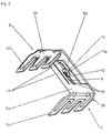
- the crampon 5 consists essentially of a plate-like, flat housing 8 made of plastic and two finger-like interlocking and mutually displaceable blade parts 6, 7, which consists of metal or a plastic material, for example a carbon fiber reinforced composite material.
- Each blade part 6, 7 has a base plate 6a, 7a; from each of which substantially rectangular blade elements 6b, 7b protrude with three blades 6c, 7c, which are of different lengths.
- the in Fig. 1 is shown, the shortest blades 6c, 7c are closer to the toe 1.
- Each base plate 6a, 7a has two mutually parallel fingers 16, 17, which are the same length and are arranged or formed such that in each case one of the fingers 16, 17 of a blade member 6 and 7 between the two fingers 16 and 17 of the other blade part 6 or 7 can be inserted.
- the base plates 6a, 7a and the fingers 16, 17 are in one plane. If the fingers 16 and 17 are completely assembled, the base plates 6a, 7a together form a largely closed, rectangular plate. In this position, the blades are 6c and 7c in the shortest possible distance from each other, so that the crampons 5 can be used on a narrow ski.
- the extent of the mutual engagement of the fingers 16, 17 is variable and determines the mutual distance of the blade elements 6b, 7b, so that the crampons 5 can be adapted to different widths of ski.
- the blade parts 6, 7 are fixable to each other in three different positions.
- a clamping or locking arrangement 11 is provided, which in the embodiment shown has a screw with a screw head 11a and a nut 11b, wherein the screw head 11a of the inside of the blade parts 6, 7 and the nut 11b of the outside of the blade parts. 6 , 7 is assigned.
- the screw 11 is disposed in the space between the inner fingers 16, 17.
- the finger 16 On the inside of one of these two fingers, here the finger 16, is at the edge of a shallow recess 9 (FIG. Fig. 2 ) extending in the longitudinal direction of the finger 16, which is provided with three Rasteinbuchtitch 10 for the screw head 11a, so that so three different mutual positions of the interlocking fingers 16 and 17 can be adjusted by appropriate positioning of the screw head 11a.
- the adjustment is made possible in particular at consistent intervals.
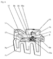
- FIG. 4 shows, the fingers 16, 17 of the two blade parts 6, 7 slidably mounted in the housing, the respective outer fingers 16, 17 in separate guide tunnels 8a, the two inner fingers 16, 17 together in a wider guide tunnel 8b.
- the screw head 11a is received in a recess on the inside of the housing 8, the nut 11b is held in a receptacle 8d of the housing 8. In this way, a comfortable adjustment of the blade parts 6, 7 to each other is possible.
- two tabs 12 are formed with pin-like locking elements 14 which can be snapped to not shown locking openings on the underside of the sole support member 2a.
- the housing 8 of the harscheiser 5 is fixed to the connecting part 2c of the binding plate 2.
- pivot pins 15 are formed on the outside of the housing 8, on each of which a manually operable latch 18 is rotatably mounted.
- Each latch 18 has an actuating arm 18a and a latching arm 18b, which has a recess 19, by means of which the snap latch 18 on the respective longitudinal side of the connecting part 2c of the binding plate 2 can be snapped.
- the crampon 5 according to the invention can be attached to the binding plate 2 in a simple manner and removed therefrom. Care is taken to ensure that the mutual distance of the two blade parts 6, 7 and thus the mutual spacing of the blades 6c and 7c of the respective ski width is adjusted before fastening the harscheiser 5. If necessary, the clamp between the blade parts 6, 7 is released by turning the screw 11, made a corresponding adjustment and the blade parts 6, 7 clamped again. Now only needs the housing 8 to be fixed to the binding plate 2 by the two locking elements 14 are snapped on the underside of the sole support member 2a and the two latch 18 are pivoted about the pivot pin 15 so that their locking arms 18b in the recesses 19 of the connecting part Snap in 2c. To remove the harscheiser 5, the two latch 18 are rotated about their actuating arms 18a until the latching arms 18b come out of the recesses 19. Now the crampon 5 can be removed from the binding plate 2.
- the invention is not limited to the illustrated and described embodiment.
- the blade parts may have deviating executed elements that run side by side or one above the other and whose mutual position is changeable and fixable.
- the locking can be done in other ways, for example, such that no tools are required for their operation.
- the locking or attachment of the harscheisen to the binding plate can be done in other ways.
- a stepless mutual adjustment of the blade parts can be provided.
- the blade parts can also be locked or jammed together in their chosen mutual position. Also possible is a locking or clamping of the blade parts on the binding plate or the frame.
Landscapes
- Clamps And Clips (AREA)
Description
- Die Erfindung betrifft ein Harscheisen zur Verwendung mit einer Tourenskibindung, die eine Bindungsplatte bzw. ein Bindungsgestell aufweist, welche bzw. welches an einem skifesten Basisteil schwenkbar angelenkt ist, wobei das Harscheisen mittels Befestigungselementen an der Bindungsplatte bzw. am Bindungsgestell lösbar befestigbar ist und zwei in der Gebrauchslage nach unten über den Ski überstehende Klingenelemente aufweist.
- Ein derartiges Harscheisen ist beispielsweise aus der
DE 91 11 722 U1 bekannt. Dieses Harscheisen weist eine Grundplatte und zwei von der Grundplatte ausgehende seitliche Führungsstege mit in der Gebrauchslage zum Eingreifen in den Schnee nach unten gerichteten Klingen auf. Des weiteren besitzt das Harscheisen Befestigungselemente zum Befestigen seiner Grundplatte an einem auf dem Ski schwenkbar angeordneten Bindungsgestell oder einer Bindungsplatte, wobei die Befestigungselemente derart gestaltet sind, dass sie eine Befestigung der Grundplatte gegenüber dem Ski sowohl in einer ersten Lage als auch in einer gegenüber dieser ersten Lage in Skilängsrichtung um 180° verdrehten zweiten Lage gestatten. Die an den Führungsstegen ausgebildeten Klingen weisen unterschiedliche Höhen auf, sodass in der ersten Lage der Grundplatte die kürzeren und in der zweiten Lage der Grundplatte die längeren Klingen die vorderen sind. - Die
US 1,345,988 A1 offenbart ein Harscheisen, hier als "break mechanism" bezeichnet, welches an den Skilängsseiten befestigt wird und zwei ineinander greifende und dadurch gegeneinander verschiebbar angeordnete längliche Elemente aufweist, deren gegenseitige Lage mittels einer Schraube fixierbar ist, die von oben durch das eine Element, welches in seinem Inneren das andere Element aufnimmt, geführt ist. Wegen seiner relativ großen Bauhöhe kann dieses Harscheisen nur außerhalb eines Bindungsbereiches am Ski angeordnet werden. Die Anpassung des Harscheisens an eine bestimmte Skibreite ist umständlich, da auch eine Befestigung des Harscheisens an den Skilängsseiten zu erfolgen hat. - Aus der
EP 1 527 803 A1 ist eine Tourenskibindung mit einem Harscheisen bekannt, welches mindestens ein mit Klingen versehenes Klingenelement aufweist, das im am Ski oder an der Skibindung angebrachten Zustand um eine Schwenkachse in eine Einsatzstellung verstellbar ist, in welcher die Klingen wenigsten teilweise nach unten über den Ski vorstehen, und in eine Bereitschaftsstellung verstellbar ist, in welcher die Klingen oberhalb der Skilauffläche angeordnet sind. -
EP2327457 A2 offenbart ein Harscheisen, das alle Merkmale des Präambels des Anspruchs 1 enthält. - Harscheisen, wie sie beispielsweise aus dem oben genannten deutschen Gebrauchsmuster bekannt sind, werden üblicherweise in mehreren Breiten hergestellt, sodass für unterschiedlich breite Ski unterschiedliche breite Harscheisen angeboten werden.
- Der Erfindung liegt die Aufgabe zugrunde, ein auf einfache Weise an unterschiedliche Skibreiten anpassbares Harscheisen zur Verfügung zu stellen.
- Gelöst wird die gestellte Aufgabe erfindungsgemäß dadurch, dass die Klingenteile an oder in einem plattenartig ausgeführten Gehäuse verschiebbar angeordnet sind, wobei die beiden Klingenteile mit dem Gehäuse verklemm- bzw. verriegelbar sind, wobei der eine Klingenteil zumindest ein Element aufweist, welches neben oder in zumindest teilweiser Überdeckung mit einem Element des anderen Klingenteils zu positionieren ist, und wobei die Klemm- bzw. Riegelanordnung die gegenseitige Lage dieser beiden Elemente fixiert. Die Erfindung stellt daher ein Harscheisen zur Verfügung, welches bei einfacher, zweckmäßiger und robuster Ausführung an unterschiedlich breite Ski anpassbar ist. Die verschiebbare Anordnung der beiden Klingenteile an oder in einem plattenartig ausgeführten Gehäuse erleichtert das Hantieren beim Verstellen, da das Gehäuse die Klingenteile hält. Das Gehäuse bildet bei dieser Ausführung mit den Klingenteilen quasi eine Einheit.
- Es ist von Vorteil, wenn die Befestigungselemente zum lösbaren Befestigen des Harscheisens an der Bindungsplatte bzw. dem Bindungsgestell am Gehäuse angeordnet sind. Dadurch kann das erfindungsgemäße Harscheisen besonders bequem an der Bindungsplatte oder dem Bindungsgestell befestigt werden.
- Einen besonders zweckmäßigen und kompakten Aufbau weist das Harscheisen insbesondere dann auf, wenn jeder Klingenteil zwei parallel verlaufende fingerartige Elemente besitzt, wobei jeweils ein fingerartiges Element des einen Klingenteils zwischen den zwei fingerartigen Elementen des anderen Klingenteils einfügbar ist.
- Die Klemm- bzw. Riegelanordnung kann ebenfalls auf unterschiedliche Weisen ausgeführt werden. Bei einer simplen und bevorzugten Ausführung ist die Klemm- bzw. Riegelanordnung eine Schraube mit Schraubenkopf und Mutter, wobei die Mutter vorzugsweise in einer Aufnahme im Gehäuse gehalten ist. Dadurch kann durch ein Drehen des Schraubenkopfes die gewünschte gegenseitige Lage der Klingenteile fixiert und bei Bedarf gelöst werden.
- Die gegenseitige Lage der Klingenteile kann stufenlos einstellbar und fixierbar sein, bei einer bevorzugten Ausführung ist sie jedoch in definierten Abständen, beispielsweise in drei Abständen, einstell- und fixierbar.
- Es erleichtert die Verstellung der gegenseitigen Lage der Klingenteile, wenn diese im Gehäuse in Führungen gleitbeweglich verschiebbar sind.
- Die bereits erwähnten Befestigungselemente zum lösbaren Fixieren des Harscheisens an der Bindungsplatte bzw. dem Bindungsgestell werden bei einer bevorzugten Ausführungsform der Erfindung an der Außenseite des Gehäuses angeordnet.
- Besonders einfach gestaltet sich die Befestigung des Harscheisens wenn Rastelemente vorgesehen sind, welche an der Bindungsplatte einschnappbar sind. Dabei können Rastelemente vorgesehen sein, die an den Längsseiten oder an der Unterseite der Bindungsplatte einschnappbar sind. Die Rastelemente können ferner am Gehäuse drehbar gelagert sein.
- Weitere Merkmale, Vorteile und Einzelheiten der Erfindung werden anhand der schematischen Zeichnung, die ein Ausführungsbeispiel darstellt, näher beschrieben. Dabei zeigen
- Fig. 1
- ein an einer Tourenskibindung angeordnetes erfindungsgemäßes Harscheisen,
- Fig. 2
- eine Ansicht der Klingenteile,
- Fig. 3
- eine Schrägansicht des Harscheisens und
- Fig. 4
- eine Schnittansicht des Harscheisens.
-
Fig. 1 zeigt den vorderen Bereich einer Skibindung zum Skitourengehen, welche einen Vorderbacken 1 und einen nicht gezeigten Fersenbacken aufweist, in vereinfachter Darstellung. Die Skibindung weist eine längliche Bindungsplatte 2 auf, welche bei am Ski montierter Bindung um eine parallel zur Oberseite des Skis und quer zur Skilängsrichtung verlaufende Drehachse 4 an einem skifest angeordneten Basisteil 3 schwenkbar angelenkt ist. Die Bindungsplatte 2 besteht aus mehreren, miteinander fest verbundenen Teilen, insbesondere einem Sohlenauflageteil 2a, einem schmäleren, als Hohlprofil ausgebildeten Mittelteil 2b, an dessen nicht gezeigten Endbereich der Fersenbacken der Skibindung angeordnet ist, und einem Verbindungsteil 2c zwischen dem Mittelteil 2b und dem Sohlenauflageteil 2a. Am vorderen Ende der Bindungsplatte 2 ist zum Halten der Schuhspitze eines nicht gezeigten Skischuhs der Vorderbacken 1 angebracht. Die Bindungsplatte 2 kann an ihrem rückwärtigen Bereich in nicht dargestellter Weise am Ski lösbar verriegelt werden, sodass die Skibindung wahlweise zum Abfahren und zum Aufsteigen benützt werden kann. Zum Aufsteigen wird die Verriegelung gelöst und es kann die gewünschte Neigung der Bindungsplatte relativ zur Skioberseite mittels einer ebenfalls nicht gezeigten Steighilfe eingestellt werden. Bei Untergründen aus Harsch oder Eis kann beim Aufsteigen zusätzlich zur Steighilfe ein Harscheisen 5 verwendet werden. - Das Harscheisen 5 gemäß der Erfindung besteht im Wesentlichen aus einem plattenartigen, flachen Gehäuse 8 aus Kunststoff und zwei fingerartig ineinandergreifenden und gegeneinander verschiebbaren Klingenteilen 6, 7, welche aus Metall oder einem Kunststoffmaterial, beispielsweise einem mit Karbonfasern verstärkten Verbundmaterial, besteht. Jeder Klingenteil 6, 7 besitzt eine Basisplatte 6a, 7a; von welcher jeweils im Wesentlichen rechtwinkelig Klingenelemente 6b, 7b mit je drei Klingen 6c, 7c abragen, welche unterschiedlich lang ausgeführt sind. In der Gebrauchslage des Harscheisens 5, die in
Fig. 1 gezeigt ist, befinden sich die kürzesten Klingen 6c, 7c näher beim Vorderbacken 1. - Jede Basisplatte 6a, 7a weist zwei parallel zueinander verlaufende Finger 16, 17 auf, welche gleich lang sind und derart angeordnet bzw. ausgebildet sind, dass jeweils einer der Finger 16, 17 des einen Klingenteils 6 bzw. 7 zwischen die beiden Finger 16 bzw. 17 des jeweils anderen Klingenteils 6 bzw. 7 eingefügt werden kann. Bei zusammengefügten Klingenteilen 6 und 7 befinden sich die Basisplatten 6a, 7a und die Finger 16, 17 in einer Ebene. Sind die Finger 16 und 17 komplett zusammengefügt, bilden die Basisplatten 6a, 7a gemeinsam eine weitgehend geschlossene, rechteckige Platte. In dieser Lage befinden sich die Klingen 6c und 7c im kürzest möglichen Abstand zueinander, sodass das Harscheisen 5 auf einem schmalen Ski verwendet werden kann. Das Ausmaß des gegenseitigen Ineinandergreifens der Finger 16, 17 ist veränderbar und bestimmt den gegenseitigen Abstand der Klingenelemente 6b, 7b, sodass das Harscheisen 5 an unterschiedlich breite Ski angepasst werden kann. Bei dem in den Figuren dargestellten Harscheisen 5 ist vorgesehen, dass die Klingenteile 6, 7 in drei unterschiedlichen Lagen zueinander fixierbar sind. Zu diesem Zweck ist eine Klemm- bzw. Riegelanordnung 11 vorgesehen, welche bei der gezeigten Ausführungsform eine Schraube mit einem Schraubenkopf 11a und eine Mutter 11b aufweist, wobei der Schraubenkopf 11a der Innenseite der Klingenteile 6, 7 und die Mutter 11b der Außenseite der Klingenteile 6, 7 zugeordnet ist. Die Schraube 11 ist im Zwischenraum zwischen den inneren Fingern 16, 17 angeordnet. An der Innenseite einer dieser beiden Finger, hier des Fingers 16, ist am Rand eine flache Vertiefung 9 (
Fig. 2 ) in Längsrichtung des Fingers 16 verlaufend ausgebildet, welche mit drei Rasteinbuchtungen 10 für den Schraubenkopf 11a versehen ist, sodass derart drei unterschiedliche gegenseitigen Lagen der ineinander greifenden Finger 16 und 17 durch entsprechende Positionierung des Schraubenkopfes 11a eingestellt werden können. Die Verstellung wird insbesondere in übereinstimmenden Abständen ermöglicht. - Wie
Fig. 4 zeigt, sind die Finger 16, 17 der beiden Klingenteile 6, 7 im Gehäuse verschiebbar gelagert, die jeweils äußeren Finger 16, 17 in separaten Führungstunneln 8a, die beiden inneren Finger 16, 17 gemeinsam in einem breiteren Führungstunnel 8b. Der Schraubenkopf 11a ist in einer Vertiefung an der Innenseite des Gehäuses 8 aufgenommen, die Schraubenmutter 11b ist in einer Aufnahme 8d des Gehäuses 8 festgehalten. Auf diese Weise ist eine komfortable Verstellung der Klingenteile 6, 7 zueinander möglich. - An der Außenseite des Gehäuses 8 sind zwei Laschen 12 mit zapfenartigen Rastelementen 14 ausgebildet, welche an nicht gezeigten Rastöffnungen an der Unterseite des Sohlenauflageteils 2a eingeschnappt werden können. Zusätzlich wird das Gehäuse 8 des Harscheisens 5 am Verbindungsteil 2c der Bindungsplatte 2 fixiert. Zu diesem Zweck sind an der Außenseite des Gehäuses 8 Schwenkzapfen 15 ausgebildet, an welchen jeweils ein von Hand aus betätigbarer Schnappriegel 18 drehbar gelagert ist. Jeder Schnappriegel 18 weist einen Betätigungsarm 18a und einen Rastarm 18b auf, wobei dieser eine Ausnehmung 19 aufweist, mittels welcher der Schnappriegel 18 an der jeweiligen Längsseite des Verbindungsteils 2c der Bindungsplatte 2 einschnappbar ist.
- Das erfindungsgemäße Harscheisen 5 lässt sich auf einfache Weise an der Bindungsplatte 2 befestigen und von dieser entfernen. Vor dem Befestigen des Harscheisens 5 wird darauf geachtet, dass der gegenseitige Abstand der beiden Klingenteile 6, 7 und damit der gegenseitige Abstand der Klingen 6c und 7c der jeweiligen Skibreite angepasst ist. Bei Bedarf wird durch Verdrehen der Schraube 11 die Klemmung zwischen den Klingenteilen 6, 7 gelöst, eine entsprechende Verstellung vorgenommen und die Klingenteile 6, 7 wieder geklemmt. Nun braucht lediglich das Gehäuse 8 an der Bindungsplatte 2 fixiert zu werden, indem die beiden Rastelemente 14 an der Unterseite des Sohlenauflageteils 2a eingeschnappt werden und die beiden Schnappriegel 18 derart um die Schwenkzapfen 15 geschwenkt werden, dass ihre Rastarme 18b in den Ausnehmungen 19 des Verbindungsteils 2c einschnappen. Zum Entfernen des Harscheisens 5 werden die beiden Schnappriegel 18 über ihre Betätigungsarme 18a verdreht, bis die Rastarme 18b aus den Ausnehmungen 19 frei kommen. Nun kann das Harscheisen 5 von der Bindungsplatte 2 abgenommen werden.
- Die Erfindung ist auf das dargestellte und beschriebene Ausführungsbeispiel nicht eingeschränkt. Die Klingenteile können abweichend ausgeführte Elemente aufweisen, die nebeneinander oder übereinander verlaufen und deren gegenseitige Lage veränderbar und fixierbar ist. Die Verriegelung kann auf andere Weise erfolgen, beispielweise derart, dass zu ihrer Betätigung kein Werkzeug erforderlich ist. Auch die Verriegelung bzw. Befestigung des Harscheisens an der Bindungsplatte kann auf andere Weise erfolgen. Des Weiteren kann eine stufenlose gegenseitige Verstellung der Klingenteile vorgesehen sein. Die Klingenteile können ferner in ihrer gewählten gegenseitigen Lage auch miteinander verriegelt oder verklemmt werden. Möglich ist auch eine Verriegelung bzw. Klemmung der Klingenteile an der Bindungsplatte bzw. dem Gestell.
-
- 1 .................... Vorderbacken
- 2 .................... Tourenplatte
- 2a ..................... Sohlenauflageteil
- 2b ..................... Mitteilteil
- 2c ..................... Verbindungsteil
- 3 .................... skifester Basisteil
- 4 .................... Schwenkachse
- 5 .................... Harscheisen
- 6, 7 ................... Klingenteil
- 6a, 7a................ Basisteil
- 6b, 7b ............... Klingenelement
- 6c, 7c................ Klinge
- 8 .................... Gehäuse
- 8a ..................... Führungstunnel
- 8b ..................... Führungstunnel
- 8d ..................... Aufnahme
- 9 .................... flache Vertiefung
- 10................... Rasteinbuchtung
- 11................... Riegel
- 11a ................... Schraubenkopf
- 11b ................... Mutter
- 12 ..................... Lasche
- 14................... Rastelement
- 15................... Schwenkzapfen
- 16................... Finger
- 17................... Finger
- 18................... Schnappriegel
- 18a ................... Betätigungsarm
- 18b ................... Rastarm
- 19 ..................... Ausnehmung
Claims (10)
- Harscheisen (5) zur Verwendung mit einer Tourenskibindung, die eine Bindungsplatte (2) bzw. ein Bindungsgestell aufweist, welche bzw. welches an einem skifesten Basisteil (3) schwenkbar angelenkt ist, wobei das Harscheisen (5) mittels Befestigungselementen an der Bindungsplatte (2) bzw. am Bindungsgestell lösbar befestigbar ist und zwei in der Gebrauchslage nach unten über den Ski überstehende Klingenelemente (6b, 7b) aufweist,
dadurch gekennzeichnet,
dass die Klingenelemente (6b, 7b) an zwei gegeneinander verschiebbaren Klingenteilen (6, 7) angeordnet sind, deren gegenseitige Lage mittels einer Klemm- oder Riegelanordnung (11) fixierbar ist und welche an oder in einem plattenartig ausgeführten Gehäuse (8) verschiebbar angeordnet sind, wobei die beiden Klingenteile (6,7) mit dem Gehäuse (8) verklemm- bzw. verriegelbar sind, wobei der eine Klingenteil (6) zumindest ein Element aufweist, welches neben oder in zumindest teilweiser Überdeckung mit einem Element des anderen Klingenteils (7) zu positionieren ist, und wobei die Klemm- bzw. Riegelanordnung (11) die gegenseitige Lage dieser beiden Elemente fixiert. - Harscheisen (5) nach Anspruch 1, dadurch gekennzeichnet, dass die Befestigungselemente zum lösbaren Befestigen des Harscheisens (5) an der Bindungsplatte (2) bzw. dem Bindungsgestell am Gehäuse (8) vorgesehen sind.
- Harscheisen (5) nach Anspruch 1 oder 2, dadurch gekennzeichnet, dass jeder Klingenteil (6, 7) zwei parallel verlaufende fingerartige Elemente (16, 17) aufweist, wobei jeweils ein fingerartiges Element (16) des einen Klingenteils (6) zwischen den zwei fingerartigen Elemente (17) des anderen Klingenteils (7) einfügbar ist.
- Harscheisen (5) nach einem der Ansprüche 1 bis 3, dadurch gekennzeichnet, dass die Klemm- bzw. Riegelanordnung eine Schraube (11) mit Schraubenkopf (11a) und Mutter (11b) umfasst, welche insbesondere in einer Aufnahme (8d) im Gehäuse (8) gehalten ist.
- Harscheisen (5) nach einem der Ansprüche 1 bis 4, dadurch gekennzeichnet, dass die gegenseitige Lage der Klingenteile (6, 7) in definierten Abständen, insbesondere in drei Abständen, einstell- und fixierbar ist.
- Harscheisen (5) nach einem der Ansprüche 1 bis 5, dadurch gekennzeichnet, dass im Gehäuse (8) Führungen zum gleitbeweglichen Verschieben der Klingenteile (6, 7) ausgebildet sind.
- Harscheisen (5) nach Anspruch 2, dadurch gekennzeichnet, dass die Befestigungselemente Rastelemente umfassen, welche an der Bindungsplatte (2) einschnappbar sind.
- Harscheisen (5) nach Anspruch 7, dadurch gekennzeichnet, dass Rastelemente vorgesehen sind, die an der Unterseite der Bindungsplatte (2) einschnappbar sind.
- Harscheisen (5) nach Anspruch 7, dadurch gekennzeichnet, dass Rastelemente vorgesehen sind, die an den Längsseiten der Bindungsplatte (2) einschnappbar sind.
- Harscheisen (5) nach Anspruch 9, dadurch gekennzeichnet, dass die Rastelemente an Drehzapfen des Gehäuses (8) drehbar gelagert sind.
Applications Claiming Priority (1)
| Application Number | Priority Date | Filing Date | Title |
|---|---|---|---|
| AT11502011A AT510854B1 (de) | 2011-08-10 | 2011-08-10 | Harscheisen |
Publications (2)
| Publication Number | Publication Date |
|---|---|
| EP2556865A1 EP2556865A1 (de) | 2013-02-13 |
| EP2556865B1 true EP2556865B1 (de) | 2016-07-20 |
Family
ID=46598413
Family Applications (1)
| Application Number | Title | Priority Date | Filing Date |
|---|---|---|---|
| EP12178820.2A Active EP2556865B1 (de) | 2011-08-10 | 2012-08-01 | Harscheisen |
Country Status (2)
| Country | Link |
|---|---|
| EP (1) | EP2556865B1 (de) |
| AT (1) | AT510854B1 (de) |
Citations (2)
| Publication number | Priority date | Publication date | Assignee | Title |
|---|---|---|---|---|
| DE3309295A1 (de) * | 1983-03-16 | 1984-09-20 | Hans-Dieter 7121 Gemmrigheim Layh | Brems- und geschwindigkeitssteuereinrichtung fuer ski |
| EP2327457A2 (de) * | 2009-11-27 | 2011-06-01 | Atk Race S.R.L. | Verbesserter Vorderbacken für eine Alpinskibindung |
Family Cites Families (8)
| Publication number | Priority date | Publication date | Assignee | Title |
|---|---|---|---|---|
| US1345988A (en) * | 1919-07-14 | 1920-07-06 | Brager Arvid | Skee-brake |
| FR2179609B1 (de) * | 1972-04-10 | 1976-10-29 | Pittier Paul | |
| FR2223054A2 (en) * | 1972-04-10 | 1974-10-25 | Pittier Paul | Device for fixing ski anti-backward-movement strips - has downward projections on clamps engaging ski edges |
| CH610769A5 (de) * | 1976-11-25 | 1979-05-15 | Hans Wehrli | |
| DE2937574A1 (de) * | 1979-09-17 | 1981-04-02 | Manfred Gerhard 7800 Freiburg Huch | Mechanische steighilfe fuer langlauf- und/oder kombinationsski |
| DE9111722U1 (de) | 1991-09-19 | 1991-12-12 | Burger, Simon, 8047 Karlsfeld | Harscheisen |
| EP1527803B1 (de) * | 2003-10-30 | 2008-08-06 | Fritschi AG - Swiss Bindings | Skiausrüstung mit Harscheisen |
| FR2886863B1 (fr) * | 2005-06-09 | 2008-05-23 | Look Fixations Sa Sa | Dispositif de freinage pour planche de glisse de largeur reglable |
-
2011
- 2011-08-10 AT AT11502011A patent/AT510854B1/de not_active IP Right Cessation
-
2012
- 2012-08-01 EP EP12178820.2A patent/EP2556865B1/de active Active
Patent Citations (2)
| Publication number | Priority date | Publication date | Assignee | Title |
|---|---|---|---|---|
| DE3309295A1 (de) * | 1983-03-16 | 1984-09-20 | Hans-Dieter 7121 Gemmrigheim Layh | Brems- und geschwindigkeitssteuereinrichtung fuer ski |
| EP2327457A2 (de) * | 2009-11-27 | 2011-06-01 | Atk Race S.R.L. | Verbesserter Vorderbacken für eine Alpinskibindung |
Also Published As
| Publication number | Publication date |
|---|---|
| AT510854B1 (de) | 2012-07-15 |
| AT510854A4 (de) | 2012-07-15 |
| EP2556865A1 (de) | 2013-02-13 |
Similar Documents
| Publication | Publication Date | Title |
|---|---|---|
| DE2321669C3 (de) | Rollschuh | |
| DE4135899A1 (de) | Kupplungsvorrichtung zwischen schi und schischuh mit einer laengenverstellvorrichtung | |
| EP1314458A1 (de) | Anordnung für eine auf einem Ski positionierbare Skibindung | |
| DE29618514U1 (de) | Teilbares Snowboard mit Bindungs- und Verbindungssystem | |
| CH642553A5 (de) | Skibremse. | |
| EP1559455B1 (de) | Tourengeeignete Skibindung | |
| EP3554656B1 (de) | Langlauf- oder tourenskibindung | |
| EP0581802B1 (de) | Sportschuh | |
| EP2556865B1 (de) | Harscheisen | |
| DE3132636C2 (de) | "Sicherheitsskibindung zum Tourengehen" | |
| DE19703774A1 (de) | Bindungsvorrichtung für teilbare Snowboards | |
| DE2442902A1 (de) | Sicherheitsbindung fuer skier | |
| EP1764138B1 (de) | Vorrichtung zum Positionieren einer zwei Skibindungsteile aufweisenden Skibindung auf einem Ski | |
| CH653265A5 (de) | Verstelleinrichtung fuer backen. | |
| EP1446202B2 (de) | Anordnung fur eine auf einem ski positionierbare skibindung | |
| EP4267266B1 (de) | Lagerungsvorrichtung für eine skibindung | |
| AT507889B1 (de) | Skibindung | |
| DE20121473U1 (de) | Multifunktionaler Ski | |
| EP1669112B1 (de) | Bindungssystem für Skier | |
| DE3744613C2 (de) | ||
| DE2652654A1 (de) | Gehhilfe fuer skischuhe | |
| AT12706U1 (de) | Skibindung | |
| AT368015B (de) | Skibremse | |
| EP1759742B1 (de) | Skibindung | |
| EP4631588A1 (de) | Skibremse |
Legal Events
| Date | Code | Title | Description |
|---|---|---|---|
| PUAI | Public reference made under article 153(3) epc to a published international application that has entered the european phase |
Free format text: ORIGINAL CODE: 0009012 |
|
| AK | Designated contracting states |
Kind code of ref document: A1 Designated state(s): AL AT BE BG CH CY CZ DE DK EE ES FI FR GB GR HR HU IE IS IT LI LT LU LV MC MK MT NL NO PL PT RO RS SE SI SK SM TR |
|
| AX | Request for extension of the european patent |
Extension state: BA ME |
|
| 17P | Request for examination filed |
Effective date: 20130801 |
|
| RBV | Designated contracting states (corrected) |
Designated state(s): AL AT BE BG CH CY CZ DE DK EE ES FI FR GB GR HR HU IE IS IT LI LT LU LV MC MK MT NL NO PL PT RO RS SE SI SK SM TR |
|
| 17Q | First examination report despatched |
Effective date: 20150903 |
|
| GRAP | Despatch of communication of intention to grant a patent |
Free format text: ORIGINAL CODE: EPIDOSNIGR1 |
|
| INTG | Intention to grant announced |
Effective date: 20160512 |
|
| GRAS | Grant fee paid |
Free format text: ORIGINAL CODE: EPIDOSNIGR3 |
|
| GRAA | (expected) grant |
Free format text: ORIGINAL CODE: 0009210 |
|
| AK | Designated contracting states |
Kind code of ref document: B1 Designated state(s): AL AT BE BG CH CY CZ DE DK EE ES FI FR GB GR HR HU IE IS IT LI LT LU LV MC MK MT NL NO PL PT RO RS SE SI SK SM TR |
|
| REG | Reference to a national code |
Ref country code: GB Ref legal event code: FG4D Free format text: NOT ENGLISH |
|
| REG | Reference to a national code |
Ref country code: CH Ref legal event code: EP |
|
| REG | Reference to a national code |
Ref country code: IE Ref legal event code: FG4D Free format text: LANGUAGE OF EP DOCUMENT: GERMAN |
|
| REG | Reference to a national code |
Ref country code: AT Ref legal event code: REF Ref document number: 813563 Country of ref document: AT Kind code of ref document: T Effective date: 20160815 |
|
| REG | Reference to a national code |
Ref country code: FR Ref legal event code: PLFP Year of fee payment: 5 |
|
| REG | Reference to a national code |
Ref country code: DE Ref legal event code: R096 Ref document number: 502012007693 Country of ref document: DE |
|
| REG | Reference to a national code |
Ref country code: LT Ref legal event code: MG4D |
|
| REG | Reference to a national code |
Ref country code: NL Ref legal event code: MP Effective date: 20160720 |
|
| PG25 | Lapsed in a contracting state [announced via postgrant information from national office to epo] |
Ref country code: BE Free format text: LAPSE BECAUSE OF NON-PAYMENT OF DUE FEES Effective date: 20160831 |
|
| PG25 | Lapsed in a contracting state [announced via postgrant information from national office to epo] |
Ref country code: RS Free format text: LAPSE BECAUSE OF FAILURE TO SUBMIT A TRANSLATION OF THE DESCRIPTION OR TO PAY THE FEE WITHIN THE PRESCRIBED TIME-LIMIT Effective date: 20160720 Ref country code: HR Free format text: LAPSE BECAUSE OF FAILURE TO SUBMIT A TRANSLATION OF THE DESCRIPTION OR TO PAY THE FEE WITHIN THE PRESCRIBED TIME-LIMIT Effective date: 20160720 Ref country code: NO Free format text: LAPSE BECAUSE OF FAILURE TO SUBMIT A TRANSLATION OF THE DESCRIPTION OR TO PAY THE FEE WITHIN THE PRESCRIBED TIME-LIMIT Effective date: 20161020 Ref country code: FI Free format text: LAPSE BECAUSE OF FAILURE TO SUBMIT A TRANSLATION OF THE DESCRIPTION OR TO PAY THE FEE WITHIN THE PRESCRIBED TIME-LIMIT Effective date: 20160720 Ref country code: IS Free format text: LAPSE BECAUSE OF FAILURE TO SUBMIT A TRANSLATION OF THE DESCRIPTION OR TO PAY THE FEE WITHIN THE PRESCRIBED TIME-LIMIT Effective date: 20161120 Ref country code: NL Free format text: LAPSE BECAUSE OF FAILURE TO SUBMIT A TRANSLATION OF THE DESCRIPTION OR TO PAY THE FEE WITHIN THE PRESCRIBED TIME-LIMIT Effective date: 20160720 Ref country code: LT Free format text: LAPSE BECAUSE OF FAILURE TO SUBMIT A TRANSLATION OF THE DESCRIPTION OR TO PAY THE FEE WITHIN THE PRESCRIBED TIME-LIMIT Effective date: 20160720 |
|
| PG25 | Lapsed in a contracting state [announced via postgrant information from national office to epo] |
Ref country code: ES Free format text: LAPSE BECAUSE OF FAILURE TO SUBMIT A TRANSLATION OF THE DESCRIPTION OR TO PAY THE FEE WITHIN THE PRESCRIBED TIME-LIMIT Effective date: 20160720 Ref country code: GR Free format text: LAPSE BECAUSE OF FAILURE TO SUBMIT A TRANSLATION OF THE DESCRIPTION OR TO PAY THE FEE WITHIN THE PRESCRIBED TIME-LIMIT Effective date: 20161021 Ref country code: PL Free format text: LAPSE BECAUSE OF FAILURE TO SUBMIT A TRANSLATION OF THE DESCRIPTION OR TO PAY THE FEE WITHIN THE PRESCRIBED TIME-LIMIT Effective date: 20160720 Ref country code: LV Free format text: LAPSE BECAUSE OF FAILURE TO SUBMIT A TRANSLATION OF THE DESCRIPTION OR TO PAY THE FEE WITHIN THE PRESCRIBED TIME-LIMIT Effective date: 20160720 Ref country code: PT Free format text: LAPSE BECAUSE OF FAILURE TO SUBMIT A TRANSLATION OF THE DESCRIPTION OR TO PAY THE FEE WITHIN THE PRESCRIBED TIME-LIMIT Effective date: 20161121 Ref country code: SE Free format text: LAPSE BECAUSE OF FAILURE TO SUBMIT A TRANSLATION OF THE DESCRIPTION OR TO PAY THE FEE WITHIN THE PRESCRIBED TIME-LIMIT Effective date: 20160720 |
|
| REG | Reference to a national code |
Ref country code: DE Ref legal event code: R097 Ref document number: 502012007693 Country of ref document: DE |
|
| PG25 | Lapsed in a contracting state [announced via postgrant information from national office to epo] |
Ref country code: MC Free format text: LAPSE BECAUSE OF FAILURE TO SUBMIT A TRANSLATION OF THE DESCRIPTION OR TO PAY THE FEE WITHIN THE PRESCRIBED TIME-LIMIT Effective date: 20160720 Ref country code: EE Free format text: LAPSE BECAUSE OF FAILURE TO SUBMIT A TRANSLATION OF THE DESCRIPTION OR TO PAY THE FEE WITHIN THE PRESCRIBED TIME-LIMIT Effective date: 20160720 Ref country code: RO Free format text: LAPSE BECAUSE OF FAILURE TO SUBMIT A TRANSLATION OF THE DESCRIPTION OR TO PAY THE FEE WITHIN THE PRESCRIBED TIME-LIMIT Effective date: 20160720 |
|
| PLBE | No opposition filed within time limit |
Free format text: ORIGINAL CODE: 0009261 |
|
| STAA | Information on the status of an ep patent application or granted ep patent |
Free format text: STATUS: NO OPPOSITION FILED WITHIN TIME LIMIT |
|
| PG25 | Lapsed in a contracting state [announced via postgrant information from national office to epo] |
Ref country code: DK Free format text: LAPSE BECAUSE OF FAILURE TO SUBMIT A TRANSLATION OF THE DESCRIPTION OR TO PAY THE FEE WITHIN THE PRESCRIBED TIME-LIMIT Effective date: 20160720 Ref country code: CZ Free format text: LAPSE BECAUSE OF FAILURE TO SUBMIT A TRANSLATION OF THE DESCRIPTION OR TO PAY THE FEE WITHIN THE PRESCRIBED TIME-LIMIT Effective date: 20160720 Ref country code: BG Free format text: LAPSE BECAUSE OF FAILURE TO SUBMIT A TRANSLATION OF THE DESCRIPTION OR TO PAY THE FEE WITHIN THE PRESCRIBED TIME-LIMIT Effective date: 20161020 Ref country code: SK Free format text: LAPSE BECAUSE OF FAILURE TO SUBMIT A TRANSLATION OF THE DESCRIPTION OR TO PAY THE FEE WITHIN THE PRESCRIBED TIME-LIMIT Effective date: 20160720 Ref country code: SM Free format text: LAPSE BECAUSE OF FAILURE TO SUBMIT A TRANSLATION OF THE DESCRIPTION OR TO PAY THE FEE WITHIN THE PRESCRIBED TIME-LIMIT Effective date: 20160720 |
|
| REG | Reference to a national code |
Ref country code: IE Ref legal event code: MM4A |
|
| 26N | No opposition filed |
Effective date: 20170421 |
|
| GBPC | Gb: european patent ceased through non-payment of renewal fee |
Effective date: 20161020 |
|
| PG25 | Lapsed in a contracting state [announced via postgrant information from national office to epo] |
Ref country code: GB Free format text: LAPSE BECAUSE OF NON-PAYMENT OF DUE FEES Effective date: 20161020 Ref country code: IE Free format text: LAPSE BECAUSE OF NON-PAYMENT OF DUE FEES Effective date: 20160801 |
|
| REG | Reference to a national code |
Ref country code: FR Ref legal event code: PLFP Year of fee payment: 6 |
|
| PG25 | Lapsed in a contracting state [announced via postgrant information from national office to epo] |
Ref country code: SI Free format text: LAPSE BECAUSE OF FAILURE TO SUBMIT A TRANSLATION OF THE DESCRIPTION OR TO PAY THE FEE WITHIN THE PRESCRIBED TIME-LIMIT Effective date: 20160720 Ref country code: LU Free format text: LAPSE BECAUSE OF NON-PAYMENT OF DUE FEES Effective date: 20160801 |
|
| PG25 | Lapsed in a contracting state [announced via postgrant information from national office to epo] |
Ref country code: CY Free format text: LAPSE BECAUSE OF FAILURE TO SUBMIT A TRANSLATION OF THE DESCRIPTION OR TO PAY THE FEE WITHIN THE PRESCRIBED TIME-LIMIT Effective date: 20160720 Ref country code: HU Free format text: LAPSE BECAUSE OF FAILURE TO SUBMIT A TRANSLATION OF THE DESCRIPTION OR TO PAY THE FEE WITHIN THE PRESCRIBED TIME-LIMIT; INVALID AB INITIO Effective date: 20120801 |
|
| PG25 | Lapsed in a contracting state [announced via postgrant information from national office to epo] |
Ref country code: MK Free format text: LAPSE BECAUSE OF FAILURE TO SUBMIT A TRANSLATION OF THE DESCRIPTION OR TO PAY THE FEE WITHIN THE PRESCRIBED TIME-LIMIT Effective date: 20160720 Ref country code: MT Free format text: LAPSE BECAUSE OF FAILURE TO SUBMIT A TRANSLATION OF THE DESCRIPTION OR TO PAY THE FEE WITHIN THE PRESCRIBED TIME-LIMIT Effective date: 20160720 Ref country code: TR Free format text: LAPSE BECAUSE OF FAILURE TO SUBMIT A TRANSLATION OF THE DESCRIPTION OR TO PAY THE FEE WITHIN THE PRESCRIBED TIME-LIMIT Effective date: 20160720 |
|
| REG | Reference to a national code |
Ref country code: FR Ref legal event code: PLFP Year of fee payment: 7 |
|
| PG25 | Lapsed in a contracting state [announced via postgrant information from national office to epo] |
Ref country code: AL Free format text: LAPSE BECAUSE OF FAILURE TO SUBMIT A TRANSLATION OF THE DESCRIPTION OR TO PAY THE FEE WITHIN THE PRESCRIBED TIME-LIMIT Effective date: 20160720 |
|
| PGFP | Annual fee paid to national office [announced via postgrant information from national office to epo] |
Ref country code: DE Payment date: 20250820 Year of fee payment: 14 |
|
| PGFP | Annual fee paid to national office [announced via postgrant information from national office to epo] |
Ref country code: IT Payment date: 20250825 Year of fee payment: 14 |
|
| PGFP | Annual fee paid to national office [announced via postgrant information from national office to epo] |
Ref country code: FR Payment date: 20250829 Year of fee payment: 14 Ref country code: AT Payment date: 20250821 Year of fee payment: 14 |
|
| PGFP | Annual fee paid to national office [announced via postgrant information from national office to epo] |
Ref country code: CH Payment date: 20250901 Year of fee payment: 14 |