EP2556902A1 - Installation d'alimentation en huile lubrifiante et procédé d'alimentation en huile lubrifiante - Google Patents
Installation d'alimentation en huile lubrifiante et procédé d'alimentation en huile lubrifiante Download PDFInfo
- Publication number
- EP2556902A1 EP2556902A1 EP11766038A EP11766038A EP2556902A1 EP 2556902 A1 EP2556902 A1 EP 2556902A1 EP 11766038 A EP11766038 A EP 11766038A EP 11766038 A EP11766038 A EP 11766038A EP 2556902 A1 EP2556902 A1 EP 2556902A1
- Authority
- EP
- European Patent Office
- Prior art keywords
- lubricant
- spray nozzles
- amount
- supplied
- spray
- Prior art date
- Legal status (The legal status is an assumption and is not a legal conclusion. Google has not performed a legal analysis and makes no representation as to the accuracy of the status listed.)
- Granted
Links
Images


Classifications
-
- B—PERFORMING OPERATIONS; TRANSPORTING
- B05—SPRAYING OR ATOMISING IN GENERAL; APPLYING FLUENT MATERIALS TO SURFACES, IN GENERAL
- B05B—SPRAYING APPARATUS; ATOMISING APPARATUS; NOZZLES
- B05B12/00—Arrangements for controlling delivery; Arrangements for controlling the spray area
- B05B12/08—Arrangements for controlling delivery; Arrangements for controlling the spray area responsive to condition of liquid or other fluent material to be discharged, of ambient medium or of target ; responsive to condition of spray devices or of supply means, e.g. pipes, pumps or their drive means
- B05B12/084—Arrangements for controlling delivery; Arrangements for controlling the spray area responsive to condition of liquid or other fluent material to be discharged, of ambient medium or of target ; responsive to condition of spray devices or of supply means, e.g. pipes, pumps or their drive means responsive to condition of liquid or other fluent material already sprayed on the target, e.g. coating thickness, weight or pattern
-
- B—PERFORMING OPERATIONS; TRANSPORTING
- B05—SPRAYING OR ATOMISING IN GENERAL; APPLYING FLUENT MATERIALS TO SURFACES, IN GENERAL
- B05B—SPRAYING APPARATUS; ATOMISING APPARATUS; NOZZLES
- B05B12/00—Arrangements for controlling delivery; Arrangements for controlling the spray area
- B05B12/08—Arrangements for controlling delivery; Arrangements for controlling the spray area responsive to condition of liquid or other fluent material to be discharged, of ambient medium or of target ; responsive to condition of spray devices or of supply means, e.g. pipes, pumps or their drive means
-
- B—PERFORMING OPERATIONS; TRANSPORTING
- B05—SPRAYING OR ATOMISING IN GENERAL; APPLYING FLUENT MATERIALS TO SURFACES, IN GENERAL
- B05D—PROCESSES FOR APPLYING FLUENT MATERIALS TO SURFACES, IN GENERAL
- B05D3/00—Pretreatment of surfaces to which liquids or other fluent materials are to be applied; After-treatment of applied coatings, e.g. intermediate treating of an applied coating preparatory to subsequent applications of liquids or other fluent materials
-
- B—PERFORMING OPERATIONS; TRANSPORTING
- B21—MECHANICAL METAL-WORKING WITHOUT ESSENTIALLY REMOVING MATERIAL; PUNCHING METAL
- B21B—ROLLING OF METAL
- B21B27/00—Rolls, roll alloys or roll fabrication; Lubricating, cooling or heating rolls while in use
- B21B27/06—Lubricating, cooling or heating rolls
- B21B27/10—Lubricating, cooling or heating rolls externally
-
- F—MECHANICAL ENGINEERING; LIGHTING; HEATING; WEAPONS; BLASTING
- F16—ENGINEERING ELEMENTS AND UNITS; GENERAL MEASURES FOR PRODUCING AND MAINTAINING EFFECTIVE FUNCTIONING OF MACHINES OR INSTALLATIONS; THERMAL INSULATION IN GENERAL
- F16N—LUBRICATING
- F16N7/00—Arrangements for supplying oil or unspecified lubricant from a stationary reservoir or the equivalent in or on the machine or member to be lubricated
- F16N7/30—Arrangements for supplying oil or unspecified lubricant from a stationary reservoir or the equivalent in or on the machine or member to be lubricated the oil being fed or carried along by another fluid
- F16N7/32—Mist lubrication
- F16N7/34—Atomising devices for oil
-
- B—PERFORMING OPERATIONS; TRANSPORTING
- B21—MECHANICAL METAL-WORKING WITHOUT ESSENTIALLY REMOVING MATERIAL; PUNCHING METAL
- B21B—ROLLING OF METAL
- B21B2267/00—Roll parameters
- B21B2267/10—Roughness of roll surface
-
- B—PERFORMING OPERATIONS; TRANSPORTING
- B21—MECHANICAL METAL-WORKING WITHOUT ESSENTIALLY REMOVING MATERIAL; PUNCHING METAL
- B21B—ROLLING OF METAL
- B21B37/00—Control devices or methods specially adapted for metal-rolling mills or the work produced thereby
- B21B37/28—Control of flatness or profile during rolling of strip, sheets or plates
- B21B37/30—Control of flatness or profile during rolling of strip, sheets or plates using roll camber control
- B21B37/32—Control of flatness or profile during rolling of strip, sheets or plates using roll camber control by cooling, heating or lubricating the rolls
Definitions
- the present invention relates to a facility and method of supplying a lubricant which is used in a rolling process, in particular a hot rolling process, in a process of production of steel sheet/strip, steel plate, or other ferrous metal products.
- lubricated rolling is performed for lightening the load on the rolling rolls which are used as working tools, reducing wear or seizing and the occurrence of defects caused along with the wear or seizing, securing good surface quality of the products, and various other purposes.
- the method of using the water injection method to spray and supply a mixture of water and lubricant in an emulsion state for example, see NPLT 1
- the method of supplying grease or other semisolid lubricants by air or another gas to deposit it on the rolls, etc. have been used (for example, see PLT 1).
- a solid form lubricant which is made by mixing graphite or another solid lubricant with wax, to the roll surface (for example, see PLT 2)
- a non-oil type lubricant which is made by mixing various additives with a colloidal solution, to the rolls or roll bite, etc.
- a rolling mill is provided with a plurality of spray nozzles for lubricant supply.
- a hot rolling mill for steel sheet/strip as illustrated in PLT 1 or PLT 4, is provided with a lubrication header comprised of a plurality of spray nozzles aligned in the product width direction.
- Such a configured lubrication header is designed to enable a lubricant to be supplied to the entire region where a roll and steel material contact each other.
- This lubrication header while differing depending on the size of the rolling mill, has at least two spray nozzles which are set at substantially equal intervals and in accordance with need is provided with a mechanism which enables selection of the spray nozzles to be used.
- Such a lubrication header is usually individually provided for each of the upper and lower work rolls and backup rolls. However, depending on the operating conditions of the rolling processes, sometimes it is set for just one of the upper and lower work rolls or backup rolls. In either case, when using such a lubrication header for lubricated rolling, at the present, at least two spray nozzles are used in one rolling mill for each pass so as to supply the lubricant.
- water and a lubricant are fed by separate pumps, that is, a water-feed pump device 3' and a lubricant-feed pump device 3, to a mixer of water and lubricant called an "injector 8".
- the amount of fed water and lubricant at this time are set so that the emulsion which is produced at the injector 8 becomes a predetermined concentration.
- the emulsion of the predetermined concentration which is produced at the injector 8 is fed through pipes which are branched in the span from the injector 8 to the spray nozzles 1' to be fed to the plurality of spray nozzles 1'.
- the lubricant concentration of the emulsion is, in hot rolling of steel sheet/strip, 0.2 to 1 vol% or so.
- the amount of the supplied emulsion as a whole reaches several liters to tens of liters per minute per pass.
- equipment for supplying a lubricant and method of supplying a lubricant which use a lubrication header which is provided with so-called internal mixing type two-fluid spray nozzles which are provided with mixing chambers at which the lubricant and gas are mixed inside the spray nozzles are disclosed in PLT 4.
- the lubricant is fed to the spray nozzles as much as possible without pressure in the lubricant pipes.
- Gas of less than 0.5 bar (0.05 MPa) is used to render the lubricant into a particulate or atomized state and spray and supply it from the spray nozzles.
- PLT 6 discloses a method of supplying a lubricant and equipment for supplying a lubricant which are designed to prevent scatter even if floating mist not deposited on the roll is formed when rendering a lubricant to the particulate or atomized state and spraying and supplying it from the spray nozzles by the gas atomization method.
- an air spraying mechanism is provided as a secondary nozzle at the outside of the flow paths of the spray nozzles through which the lubricant is sprayed. At the time of spraying the lubricant, air is blown from the air spraying mechanism to form a wall of air to thereby suppress splatter of the floating mist.
- NPLT 1 the Iron and Steel Institute of Japan, "Theory and Practice of Flat Product Rolling", p. 218
- a lubricant is fed from a lubricant distributor to the spray nozzles. Basically, the same amounts of lubricant are fed from the spray nozzles. Further, no consideration is given to adjusting the amount of lubricant supplied locally in the axial direction of the rolling roll. It is not possible to suppress uneven wear or roughness in the axial direction.
- an object of the present invention is to provide equipment for supplying lubricant and lubricant supply method which can locally adjust the amount of lubricant supplied in an axial direction of a rolling roll to thereby effectively suppress uneven wear or roughness in the axial direction.
- the inventors engaged in intensive studies to solve the above problem by the feed of a lubricant by the gas atomization method and as a result obtained the following discoveries.
- the present invention was made based on these discoveries and has as its gist the following:
- the amount of lubricant supplied from the spray nozzles which are positioned close to the both ends among the plurality of spray nozzles which are arranged in the axial direction of the rolling roll are made smaller than the amount of lubricant supplied from the spray nozzles which are positioned near the center. Due to this, the amount of lubricant supplied near the both ends of the rolling roll where wear and roughness occur most easily become greater and wear and roughness of the rolling roll at those regions are suppressed. As a result, the occurrence of uneven wear and roughness at the rolling roll in the axial direction of the rolling roll are suppressed.
- FIG. 2 One example of the configuration of the equipment for supplying a lubricant according to the present invention is shown in FIG. 2 .
- the equipment for supplying a lubricant according to the present invention is provided with a plurality of spray nozzles 1a and 1b, pump devices 3 which are connected to these spray nozzles 1a and 1b and feed a lubricant to these spray nozzles 1a and 1b, and a lubricant storage tank 4 which stores the lubricant.
- the lubricant which is stored inside the lubricant storage tank 4 is fed by the pump devices 3 to the spray nozzles 1a and 1b.
- the same number of pump devices 3 as the number of spray nozzles are provided.
- One pump device 3 is connected to each of the spray nozzles 1a and 1b. Due to this, the amount of the lubricant fed to the spray nozzles 1a and 1b can be set in advance for the spray nozzles 1a and 1b and can be individually adjusted during rolling for each of the spray nozzles 1a and 1b.
- any type of pump device may be used so long as being equipped with a constant rate discharge mechanism.
- a precision gear pump, trochoid pump, rocking type pump, plunger pump, etc. may be used.
- the "pump device which has a constant discharge function" referred to here is one where the precision in setting the amount of supplied lubricant is kept to a fluctuation of not more than 20% of the set value and has the function of enabling change of the amount of supplied lubricant at a speed of 0.1 cc/min or more per second.
- the pump device 3 a configuration where two or more pump devices are connected and set in parallel and made to appear to function as a single pump device is also possible. By doing this, the range of setting of the amount of supplied lubricant can be easily broadened.
- the individual pump devices which are set in parallel should have that constant discharge function.
- the method of simultaneously interlockingly operating electrical devices for adjusting the constant discharge functions of the pumps and the method of using a pump device which is provided with a plurality of pump mechanisms while being a single pump device, such as a planetary multiport gear pump.
- the number of the pump mechanisms which are provided in the pump device corresponds to the number of pump devices 3. For example, in a six-port planetary type gear pump, this is deemed as a device provided with six pump devices 3. For this reason, while in actuality a single pump device, it is deemed as six pump devices 3, so this is one aspect of the present invention.
- lubricant switches 2 may be provided for turning the supply of a lubricant ON/OFF. This enables the supply of a lubricant to be turned ON/OFF at suitable timings. Note that, the lubricant switches 2 are not essential. However, in a normal rolling mill, the pump devices 3 and spray nozzles 1 are almost always set separated by distances of at least 1 meter or more. Under such a situation, if just turning the pump devices 3 ON/OFF to turn the supply of a lubricant ON/OFF, sometimes it is not possible to perform the lubricated rolling at a suitable timing. In such a case, it is effective to introduce lubricant switches 2. On the other hand, if the pump devices 3 and the spray nozzles 1 are within 1 meter of each other, there is little need to provide the lubricant switches 2.
- the lubricant ON setting that is, when spraying a lubricant from the spray nozzle
- the lubricant OFF setting that is, when not spraying a lubricant from the spray nozzle
- the lubricant passes through the route which is shown by the broken lines in FIG. 2 and is returned to the lubricant storage tank 4. It may also be returned to the lubricant pipe between the pump device 3 and the lubricant storage tank 4.
- the equipment for supplying a lubricant according to the present invention is provided with a noncombustible gas source 5 which is connected to the spray nozzles 1a and 1b and feeds air or a noncombustible gas or other gas to these spray nozzles 1a and 1b.
- the equipment for supplying a lubricant is provided with only one noncombustible gas source 5. Pipes are branched from this single noncombustible gas source 5 whereby gas is fed to the spray nozzles 1a and 1b.
- a gas switch 6 may be installed for turning the feed of gas ON/OFF. This enables the feed of gas to the spray nozzles to be turned ON/OFF in accordance with need.
- the gas switch 6 is installed right after the noncombustible gas source 5. Between the gas switch 6 and the spray nozzles 1a and 1b, piping is branched into exactly the number of pipes corresponding to the spray nozzles. Due to this, the individual spray nozzles can be fed with gas. However, if individually turning the feed of gas ON/OFF for each spray nozzle, it is sufficient to branch the piping between the gas switch 6 and the noncombustible gas source 5 into a number of branches corresponding to the number of spray nozzles and set a number of gas switches 6 corresponding to the number of spray nozzles in the branched pipes.
- the noncombustible gas source 5 is provided with the function of adjusting the pressure of the gas which is fed to the spray nozzles. Due to this, the spray pressure of the gas from the spray nozzles can be adjusted to the suitable pressure. Note that, in the example which is shown in FIG. 2 , the spray nozzles are fed with gas of the same pressure. However, if desiring to individually change the spray pressure for each spray nozzle, it is possible to introduce pressure adjusting devices inside the branched pipes so as to set/adjust the feed pressures of the gas to the spray nozzles.
- the spray nozzles 1a and 1b spray a lubricant which is fed from the pump devices 3 together with gas which is fed from the noncombustible gas source 5 toward the rolling roll 20 (see FIG. 5 ) in a particulate or atomized state.
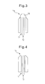
- spray nozzles 1a and 1b internal mixing type two-fluid spray nozzles 1a such as shown in FIG. 3 and external mixing type two-fluid spray nozzles 1b such as shown in FIG. 4 are used.
- an internal mixing type two-fluid spray nozzle 1a As shown in FIG. 3 , the inside of the spray nozzle is provided with a chamber (mixing chamber) 18 for mixing the gas 11 and the lubricant 12.
- a chamber mixing chamber
- an external mixing type two-fluid spray nozzle 1b as shown in FIG. 4 , such a chamber is not provided.
- the gas 11 and the lubricant 12 are mixed outside of the spray nozzle 1b.
- part of the spray nozzles of the plurality of spray nozzles are made internal mixing type two-fluid spray nozzles 1a, while the remainder are made external mixing type two-fluid spray nozzles 1b.
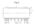
- FIG. 5 shows the arrangement of the spray nozzles 1a and 1b in the equipment for supplying a lubricant of the present invention.
- the spray nozzles 1a and 1b are arranged in the axial direction X of the rolling roll 20.
- the spray nozzles 1a and 1b are arranged in a line in the axial direction X of the rolling roll 20, but these spray nozzles 1a and 1b may also be arranged offset in the direction perpendicular to the axial direction X of the rolling roll 20.
- the intervals of arrangement between the spray nozzles 1a and 1b differ.
- the interval between the spray nozzles 1a which spray a lubricant to the center region C which is positioned at the center in the axial direction X of the rolling roll 20 (center spray nozzles) is broader than the interval between the spray nozzles 1b which spray a lubricant to the end regions E which are positioned at the two ends in the axial direction X of the rolling roll 20 (end spray nozzles).
- the width of the rolling roll 20 (length in the axial direction X) is 2000 mm
- the center region C is a region of 1200 mm at the center of the rolling roll
- the end regions E are regions of 400 mm from the ends of the rolling roll 20.
- the interval between spray nozzles 1a which spray a lubricant at the center region C is made 300 mm
- the interval between spray nozzles 1b which spray a lubricant at the end regions E is made 100 mm. Therefore, in the present embodiment, the interval between spray nozzles 1a which spray a lubricant at the center region C is three times the interval between spray nozzles 1b which spray a lubricant at the end regions E.
- the ratio of the intervals is preferably 1.5 or more.
- the spray nozzles 1a which spray a lubricant at the center region C of the rolling roll 20 are formed by internal mixing type two-fluid spray nozzles 1a, while the spray nozzles 1b which spray a lubricant at the end regions E of the rolling roll 20 are formed by external mixing type two-fluid spray nozzles 1b.
- the nozzle interval is changed between the spray nozzles which spray a lubricant at the center region C and the spray nozzles which spray a lubricant at the end regions E.
- the nozzle interval does not necessarily have to be changed in two stages in this way. It may also be changed in three stages or more stages. Alternatively, all nozzle intervals may be made different. If changing the way of looking at this, in the present invention, when dividing all of the spray nozzles into groups of spray nozzles comprised of adjoining spray nozzles, it can be said that the spray nozzles are arranged so that the nozzle interval in at least one spray nozzle group differs from the nozzle intervals in the other spray nozzle groups.
- the center region C is the center 1200 mm region of the rolling roll
- the end regions E are the regions of 400 mm from the ends of the rolling roll 20.
- the relationship between the center region C and the end regions E does not necessarily have to be such a relationship. It is also possible to make the center region C the center 800 mm of the rolling roll and make the end regions E the regions of 800 mm from the ends of the rolling roll 20 or make other various relationships.
- a single spray nozzle having a wide spray angle and a plurality of spray nozzles each having a narrow spray angle are provided in multiple stages.
- the region of the rolling roll which can be fed with a lubricant from the single spray nozzle having a wide spray angle is made the same as the region of the rolling roll which can be fed with a lubricant from the plurality of spray nozzles each having a narrow spray angle.
- the nozzle interval of the spray nozzles 1b which spray a lubricant to the end regions E becomes smaller than the nozzle interval of the spray nozzles 1a which spray a lubricant to the center region C. For this reason, it is possible to finely adjust the regions of spraying a lubricant to the rolling roll 20 in accordance with the width of the flat shaped metal material (for example, steel sheet) which is rolled by the rolling roll 20 (length of flat shaped metal material in direction vertical to direction of progression). Due to this, substantially no lubricant is supplied any longer to the regions of the rolling roll 20 which are positioned outside from the two edges of the flat shaped metal material, and thus the amount of consumption of the lubricant can be kept down.
- the flat shaped metal material for example, steel sheet
- the rolling roll 20 is more susceptible to wear and roughness at the end regions E rather than the center region C.
- the nozzle interval of the spray nozzles 1b which spray a lubricant to the end regions E is made narrow, and thus it is possible to finely control the spray of a lubricant to the end regions E of the rolling roll 20.
- internal mixing type two-fluid spray nozzles are used, while for the spray nozzles which spray a lubricant at the end regions E, external mixing type two-fluid spray nozzles are used.
- internal mixing type two-fluid spray nozzles are provided with mixing chambers at the tips of the nozzles, and thus it is easy to change the shapes of the injection ports of the spray nozzles and use as flat nozzles is possible.
- Flat nozzles enable broad widths of spray of a lubricant by single spray nozzles. For this reason, it is preferable to use internal mixing type two-fluid spray nozzles for the spray nozzles which spray a lubricant to the center region C.
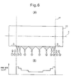
- FIG. 6(A) and FIG. 6(B) are schematic views which show amount of lubricant supplied from the spray nozzles in the equipment for supplying a lubricant of the present invention.
- FIG. 6(A) is a view which is similar to FIG. 5 and shows a rolling roll 20 and a plurality of spray nozzles.
- the spray nozzles of FIG. 6(A) are assigned numbers ascending from the left side to the right side in the figure.
- the leftmost side spray nozzle is the #1 nozzle
- the rightmost side spray nozzle is the #12 nozzle.
- the #1 nozzle to the #4 nozzle and the #9 nozzle to the #12 nozzle are external mixing type two-fluid spray nozzles
- the #5 nozzle to the #8 nozzle are internal mixing type two-fluid spray nozzles.
- FIG. 6(A) and FIG. 6(B) show the flat shaped metal material M which is rolled by the rolling roll 20. Therefore, in the illustrated example, a metal material with a width which is somewhat narrower than the width of the rolling roll 20 is rolled by the rolling roll 20.
- the graph of FIG. 6(B) shows the amount of lubricant supplied to the surface of the rolling roll 20.
- the abscissa in this graph indicates the position in the axial direction of the rolling roll 20, while the ordinate indicates the amount of lubricant which is supplied per unit time per unit surface area of the rolling roll 20 (Note that, in the Description, the "amount of supplied lubricant” means the “amount of lubricant which is supplied per unit surface area per unit time").
- the amount of lubricant supplied from the #3 nozzle and the #10 nozzle are greater than the amount of lubricant supplied from the #6 nozzle and the #7 nozzle. Further, the amount of lubricant supplied from the spray nozzles between the #3 nozzle and the #6 nozzle (that is, the #4 nozzle and the #5 nozzle) are not more than the amount of lubricant supplied from the #3 nozzle and are not less than the amount of lubricant supplied from the #6 nozzle.
- the amount of lubricant supplied from the spray nozzles between the #7 nozzle and the #10 nozzle are not less than the amount of lubricant supplied from the #7 nozzle and are not more than the amount of lubricant supplied from the #10 nozzle.
- the amount of lubricant supplied becomes gradually smaller from the #3 nozzle toward the #6 nozzle and from the #10 nozzle toward the #7 nozzle.
- the width of the metal material M is narrower to a certain extent than the width of the rolling roll 20, and thus the regions of the rolling roll 20 which are supplied with a lubricant by the #1 nozzle, the #2 nozzle, the #11 nozzle, and the #12 nozzle (regions A and B in the figure) do not bite into the metal material M and do not roll the metal material M. Therefore, the regions A and B of the rolling roll 20 do not have to be supplied with a lubricant. For this reason, in the illustrated example, a lubricant is not sprayed from the #1 nozzle, #2 nozzle, #11 nozzle, and #12 nozzle. That is, the lubricant switches 2 corresponding to the #1 nozzle, #2 nozzle, #11 nozzle, and #12 nozzle are turned OFF (when lubricant switches 2 are not provided, outputs of corresponding pump devices 3 are made zero).
- the width of the metal material is broader than the width of the metal material M which is shown in FIG. 6 and substantially the entire width of the rolling roll 20 grasps and rolls the metal material, a lubricant is sprayed from all of the spray nozzles.
- the amount of lubricant supplied from the #1 nozzle and the #12 nozzle are made larger than the amount of lubricant supplied from the #6 nozzle and #7 nozzle.
- the amount of lubricant supplied of the spray nozzles between the #1 nozzle and the #6 nozzle are made not more than the amount of lubricant supplied from the #1 nozzle and not less than the amount of lubricant supplied from the #6 nozzle.
- the amount of lubricant supplied of the spray nozzles between the #7 nozzle and the #12 nozzle are made not less than the amount of lubricant supplied from the #7 nozzle and not more than the amount of lubricant supplied from the #12 nozzle.
- the spray nozzles which supply a lubricant to the part of the rolling roll corresponding to the width of the metal material (in the example of FIG. 6 , part other than regions A and B) in the example of FIG. 6 , the #3 nozzle to the #10 nozzle
- the spray nozzles which are positioned at the two ends in the example of FIG. 6 , the #3 nozzle and the #10 nozzle
- the spray nozzles which are positioned at the center as the "center spray nozzles"
- the amount of lubricant supplied from the side spray nozzles are made greater than the amount of lubricant supplied from the center spray nozzles.
- the amount of lubricant supplied from the spray nozzles between these side spray nozzles and center spray nozzles are made not more than the amount of lubricant supplied from the side spray nozzles and not less than the amount of lubricant supplied from the center spray nozzles.
- the amount of lubricant supplied from the side spray nozzles are made not more than 5 times the amount of lubricant supplied from the center spray nozzles, preferably not more than 2 times, further, not less than 1.01 times, preferably not less than 1.03 times.
- a lubricant as explained below. That is, when the width of the metal material is 1000 mm or more, if designating, among the spray nozzles which supply a lubricant to the part of the rolling roll which corresponds to the width of the metal material M (part other than regions A and B of FIG. 6 ) (in the example of FIG.
- the amount of lubricant supplied from the spray nozzles between these side spray nozzles and center spray nozzles are made not more than the amount of lubricant supplied from the side spray nozzles and not less than the amount of lubricant supplied from the center spray nozzles.
- the amount of lubricant supplied to the spray nozzles 1a and 1b are set in advance for each of the spray nozzles 1a and 1b.
- the amount of lubricant supplied to the spray nozzles 1a and 1b may also be made individually adjustable during rolling.
- the amount of lubricant supplied to the individual spray nozzles 1a and 1b are adjusted by individually operating electrical devices for adjustment of the constant rate discharge functions of the pumps.
- These operations include utilization of a computer control system to change the amount of lubricant supplied during rolling in accordance with changes in signals detecting the rolling speed, rolling load, tension, and presence of material or some other signals or manual adjustment of the amount of lubricant supplied of certain specific spray nozzles.
- the ability for any adjustment method or setting method to be handled is a feature of the present invention.
- the adjustment method or setting method differs depending on the quality or rolling conditions of the steel material produced by the rolling mill, and thus a method suitable for the usage environment should be used for the operation.
- the method of control of the amount of lubricant supplied to the spray nozzles 1 it may be considered to change the amount of lubricant supplied to the spray nozzles 1 in accordance with the amount of wear of the rolling roll 20. That is, it may be considered to increase by 5 to 90% or so the amount of lubricant supplied to locations of the rolling roll 20 where wear has greatly progressed compared with locations where wear has not progressed.
- a profile meter (not shown) etc. is used to detect the profile of the rolling roll 20 during rolling.
- the amount of supplied lubricant is made greater for a region where the amount of wear is larger compared with other regions (region with relatively large amount of wear) compared with a region where the amount of wear is smaller compared with other regions (region with relatively small amount of wear).
- the amount of lubricant supplied from the spray nozzles consequently become as shown in FIG. 6(B) and as a result the amount of wear of the rolling roll 20 is made uniform in the axial direction.
- the method of control of the amount of lubricant supplied to the spray nozzles it may be considered to change the amount of lubricant supplied to the spray nozzles in accordance with the surface roughness of the rolling roll 20.
- a surface roughness detection device (not shown) or visual inspection etc. may be used to detect the surface roughness of the rolling roll 20.
- the amount of supplied lubricant is made greater for a region with a larger surface roughness compared with other regions (region with relatively large surface roughness) compared with a region with a smaller surface roughness compared with other regions (region with relatively small surface roughness).
- a lubricant with a dynamic viscosity at 40°C of 60 cSt or more and 800 cSt or less is used.
- a mineral oil-based lubricant, an ester-based lubricant, a lubricant comprised of these plus various additives, and, in addition to organically based ones as well, a non-oil-type lubricant of a colloidal form etc. may be used.
- the reason for using a lubricant with a dynamic viscosity at 40°C of 60 cSt or more is that if using a lubricant with a dynamic viscosity of less than 60 cSt, the deposition ability of the lubricant itself on the roll will become smaller, and a fine particle size mist component will increase when rendering the lubricant a particulate or atomized state, and thus the amount which mist without depositing on the roll will become greater making efficient deposition difficult.
- the reason for using a lubricant with a dynamic viscosity at 40°C of 800 cSt or less is that if using a lubricant with a dynamic viscosity larger than 800 cSt, the piping resistance when feeding the lubricant to the spray nozzles will become greater and smooth feed will not be possible unless pumping by a large pressure, and thus constantly and stably spraying a lubricant from the spray nozzles will become difficult and intermittent spraying may easily result. Therefore, it becomes difficult to maintain a uniform state of deposition of lubricant on the roll.
- FIG. 7 shows the state when spraying a lubricant 16 rendered into a particulate or atomized state from a spray nozzle 1 toward the surface of a sprayed object, that is, a rolling roll 20.
- the pressure of the gas has to be set at 0.05 MPa or more.
- the surface of the rolling roll 20 to which the lubricant is supplied always has roll cooling water remaining on it, and therefore to effectively make the lubricant 16 deposit on the rolling roll, the residual roll cooling water on the surface of the rolling roll 20 has to be removed.
- the gas which is sprayed from the spray nozzles has to be sprayed by a pressure of at least 0.05 MPa.
- particulate or atomized lubricant 16 is supplied to the surface of the rolling roll 20 and, simultaneously, the residual roll cooling water is blown away to thereby cause the lubricant to directly deposit on the roll. Further, gas which is sprayed and fed by a pressure of at least 0.05 MPa also exhibits the effect of making the deposited lubricant 17 uniformly even.
- the pressure at the time of feed of the lubricant to the spray nozzle has to be increased to not less than the pressure of the gas inside of the mixing chamber.
- the "pressure of the gas inside of the mixing chamber of the spray nozzle” is the pressure which acts inside of the lubricant piping near the entrance of the lubricant at the spray nozzle when not discharging a lubricant to the spray nozzle, but only feeding gas to the spray nozzle.
- the pressure inside the mixing chamber depends on the size of the spray ports and other aspects of the structure of the spray nozzle and the original pressure of the applied gas source (pressure inside of piping of gas).
- a pressure of at least 0.01 MPa has to be applied. If not, piping clogging etc. will occur and stable feed will become difficult. The higher the pressure at the time of feeding the lubricant becomes, the more difficult it becomes for piping clogging to occur. Therefore, the pressure inside the lubricant piping when pumping a lubricant to the spray nozzle is preferably at least 0.01 MPa.
- the pressure at the time of feed of the lubricant is preferably kept down to 3 MPa or less. If considering these, the pressure at the time of feed of the lubricant is preferably not less than 0.05 MPa and not more than 3 MPa.
- an external mixing type two-fluid spray nozzle differs from an internal mixing type in that there is no chamber for mixing a lubricant and gas inside the spray nozzle and in that spray nozzle a stream of sprayed lubricant and a stream of sprayed gas are made to collide right outside of the spray ports so as to spray and supply a lubricant in a particulate or atomized state on to an object to be sprayed.
- a pump device 3 should be used to pump a lubricant to a spray nozzle by a pressure of at least 0.01 MPa to 3 MPa.
- the same number of pump devices 3 as the number of spray nozzles are provided and the amount of lubricant supplied to the spray nozzles are controlled.
- internal mixing type two-fluid spray nozzles and external mixing type two-fluid spray nozzles are used.
- the type of two-fluid spray nozzles to be used is suitably selected in accordance with the conditions and location for supply of the lubricant.
- a flat nozzle enables a broad range of spraying of a lubricant to be obtained by a single spray nozzle, and thus such a spray nozzle is often suitable for supplying a lubricant to a rolling roll for steel sheet/strip.
- an external mixing type two-fluid spray nozzle often has a circular shape of spray port of the spray nozzle, and thus is suitable for uniform spraying and is often used as a round nozzle.
- FIG. 8(A) is a side view which schematically shows a water film forming system
- FIG. 8(B) is a plan view which schematically shows a water film forming system.
- FIG. 8(B) shows only the surroundings near the other end of the rolling roll 20.
- the water film forming system 25 is provided with a plurality of water spray nozzles 26 (26a, 26b, 26c) which spray water so as to form water films.
- the water spray nozzles 26 are provided with a nozzle 26a which forms a water film above spray cones from the spray nozzles of lubricant, a nozzle 26b which forms a water film below the spray cones from the spray nozzles of lubricant, and nozzles 26c which form a water film at the sides (outsides) of the spray cones from the lubricant spray nozzles at the both ends ( FIG. 8(B) shows only one).
- the amount of water which is sprayed changes depending on the spray conditions of the lubricant, but it is preferable to form the water films by a flow rate of at least 1000 cc per minute.
- the method may be considered of attaching sub nozzles for forming water films at the outside of the two-fluid spray nozzle and forming water films around the spray cones of the lubricant right after nozzle spraying. Any method may be used so long as able to form water films around spray cones from lubricant spray nozzles.
- the amount of supplied lubricant was controlled at a fifth stand of a hot final rolling mill comprised of a first stand to a seventh stand.
- the steel material was rolled from the first stand in order to the seventh stand while being rolled.
- a general low carbon steel was used for the rolled steel material. It was rolled from a thickness at the first stand entry side of 32 mm to a thickness at the seventh stand exit side of 2.3 mm.
- As the rolled steel material one with a width of 1820 mm to 1940 mm was used.
- a header comprised of spray nozzles aligned in the axial direction of the rolling roll was installed and gear pumps enabling the amount of supplied lubricant to be individually set were connected to the spray nozzles.
- spray nozzles were arranged such as shown in FIG. 5 .
- For the rolling roll a roll which was measured for roll profile after polishing was used.
- For the lubricant one having a dynamic viscosity at 40°C of 230 cSt was used.
- lubrication rolling was performed under the lubricant supply conditions which are shown in the conditions of the following Table 1 so as to roll about 245 tons.
- the roll was pulled out and the roll profile was measured to calculate the average depth of wear for each lubricant supply region of each spray nozzle and the average depth of wear for the roll as a whole.
- the ratio of the average roll wear depth at the lubricant supply region of each spray nozzle to the roll as a whole was calculated and the ratio was multiplied with the coefficient ⁇ (in the present embodiment, 1.0) and the initial amount of lubricant supplied from each spray nozzle (condition of Table 1) to obtain a value which was then used as the amount of supplied lubricant at the time of the next rolling operation.
Landscapes
- Engineering & Computer Science (AREA)
- Mechanical Engineering (AREA)
- General Engineering & Computer Science (AREA)
- Chemical & Material Sciences (AREA)
- Combustion & Propulsion (AREA)
- Oil, Petroleum & Natural Gas (AREA)
- Nozzles (AREA)
- Metal Rolling (AREA)
Priority Applications (1)
| Application Number | Priority Date | Filing Date | Title |
|---|---|---|---|
| EP15198727.8A EP3028781B1 (fr) | 2010-04-07 | 2011-04-06 | Procédé d'alimentation en lubrifiant |
Applications Claiming Priority (2)
| Application Number | Priority Date | Filing Date | Title |
|---|---|---|---|
| JP2010088371 | 2010-04-07 | ||
| PCT/JP2011/059124 WO2011126139A1 (fr) | 2010-04-07 | 2011-04-06 | Installation d'alimentation en huile lubrifiante et procédé d'alimentation en huile lubrifiante |
Related Child Applications (1)
| Application Number | Title | Priority Date | Filing Date |
|---|---|---|---|
| EP15198727.8A Division EP3028781B1 (fr) | 2010-04-07 | 2011-04-06 | Procédé d'alimentation en lubrifiant |
Publications (3)
| Publication Number | Publication Date |
|---|---|
| EP2556902A1 true EP2556902A1 (fr) | 2013-02-13 |
| EP2556902A4 EP2556902A4 (fr) | 2014-02-26 |
| EP2556902B1 EP2556902B1 (fr) | 2015-12-16 |
Family
ID=44763073
Family Applications (2)
| Application Number | Title | Priority Date | Filing Date |
|---|---|---|---|
| EP11766038.1A Active EP2556902B1 (fr) | 2010-04-07 | 2011-04-06 | Installation d'alimentation en huile lubrifiante et procédé d'alimentation en huile lubrifiante |
| EP15198727.8A Active EP3028781B1 (fr) | 2010-04-07 | 2011-04-06 | Procédé d'alimentation en lubrifiant |
Family Applications After (1)
| Application Number | Title | Priority Date | Filing Date |
|---|---|---|---|
| EP15198727.8A Active EP3028781B1 (fr) | 2010-04-07 | 2011-04-06 | Procédé d'alimentation en lubrifiant |
Country Status (8)
| Country | Link |
|---|---|
| US (1) | US8713981B2 (fr) |
| EP (2) | EP2556902B1 (fr) |
| JP (1) | JP4980504B2 (fr) |
| KR (1) | KR101299298B1 (fr) |
| CN (1) | CN102844127B (fr) |
| BR (2) | BR122020002003B1 (fr) |
| TW (1) | TWI420038B (fr) |
| WO (1) | WO2011126139A1 (fr) |
Families Citing this family (18)
| Publication number | Priority date | Publication date | Assignee | Title |
|---|---|---|---|---|
| DE102008050392A1 (de) * | 2008-06-18 | 2009-12-24 | Sms Siemag Aktiengesellschaft | Verfahren und Vorrichtung zum Schmieren von Walzen und eines Walzbandes eines Walzgerüsts |
| EP2893986A1 (fr) * | 2014-01-08 | 2015-07-15 | Siemens VAI Metals Technologies GmbH | Lubrification à l'aide de buses d'injection dotées de plusieurs orifices d'entrée d'huile |
| CA2947980C (fr) * | 2014-05-09 | 2019-01-15 | Novelis Inc. | Laminoir refroidi a l'eau et a l'huile hybride |
| GB201410562D0 (en) | 2014-06-13 | 2014-07-30 | Nicoventures Holdings Ltd | Aerosol provision system |
| US20170033184A1 (en) * | 2015-07-27 | 2017-02-02 | International Business Machines Corporation | Semiconductor device including fin having condensed channel region |
| ES2821326T3 (es) | 2015-09-21 | 2021-04-26 | Novelis Inc | Precalentamiento y control térmico de rodillos de trabajo en procedimientos de laminación de metales y sistema de control de los mismos |
| US20170186747A1 (en) * | 2015-12-29 | 2017-06-29 | International Business Machines Corporation | STRUCTURE AND METHOD FOR SiGe FIN FORMATION IN A SEMICONDUCTOR DEVICE |
| CN105752107A (zh) * | 2016-03-03 | 2016-07-13 | 武汉理工大学 | 基于轨道振动的监测自动控制摩擦改进剂施加的降噪装置 |
| JP6651986B2 (ja) * | 2016-05-27 | 2020-02-19 | 日本製鉄株式会社 | 熱間圧延における潤滑油供給方法 |
| KR102109262B1 (ko) * | 2018-08-16 | 2020-05-11 | 주식회사 포스코 | 윤활장치 |
| CN109174486B (zh) * | 2018-10-09 | 2024-09-24 | 汇专科技集团股份有限公司 | 一种低温加工喷嘴 |
| CN109333146A (zh) * | 2018-11-22 | 2019-02-15 | 青岛理工大学 | 不同工况下铣削注入切削液的方法及系统 |
| US11919059B2 (en) * | 2019-01-28 | 2024-03-05 | Primetals Technologies Germany Gmbh | Changing the effective contour of a running surface of a working roll during hot rolling of rolling stock in a roll stand to form a rolled strip |
| CN109821902B (zh) * | 2019-01-30 | 2020-09-25 | 北京首钢股份有限公司 | 一种改善硅钢边部轮廓的横向润滑能力分布方法 |
| KR102239179B1 (ko) * | 2019-10-15 | 2021-04-12 | 주식회사 포스코 | 압연설비의 혼합용액 공급장치 |
| CN114101324B (zh) * | 2021-10-29 | 2023-08-25 | 马鞍山钢铁股份有限公司 | 一种汽车用无机自润滑镀锌钢带及其生产方法 |
| KR102659536B1 (ko) * | 2021-12-15 | 2024-04-19 | 주식회사 포스코 | 강판의 도유 장치 |
| CN117019430A (zh) * | 2023-07-17 | 2023-11-10 | 芜湖莫森泰克汽车科技股份有限公司 | 一种油脂雾化喷嘴及喷雾方法 |
Family Cites Families (19)
| Publication number | Priority date | Publication date | Assignee | Title |
|---|---|---|---|---|
| US4738400A (en) * | 1987-02-11 | 1988-04-19 | Almo Manifold & Tool Co. | Spray bar assembly |
| JPH03138014A (ja) * | 1989-10-25 | 1991-06-12 | Kawasaki Steel Corp | 熱延鋼板のプロフィル制御方法 |
| JPH07290121A (ja) | 1994-04-22 | 1995-11-07 | Nippon Steel Corp | フランジを有する形鋼のユニバーサル圧延法 |
| JP3042397B2 (ja) * | 1996-03-19 | 2000-05-15 | 住友金属工業株式会社 | 調質圧延方法 |
| JP3694427B2 (ja) | 1998-10-28 | 2005-09-14 | 新日本製鐵株式会社 | 固形潤滑による孔形圧延方法 |
| US6134930A (en) | 2000-01-26 | 2000-10-24 | Morgan Construction Company | Lubrication system |
| JP2002316202A (ja) | 2001-04-18 | 2002-10-29 | Nakayama Steel Works Ltd | 板圧延用潤滑装置および潤滑剤噴射ノズル |
| JP4203236B2 (ja) * | 2001-09-21 | 2008-12-24 | 新日本製鐵株式会社 | 熱間圧延における潤滑供給方法 |
| JP4123865B2 (ja) * | 2002-08-12 | 2008-07-23 | 株式会社Ihi | ピンチロールの潤滑ミストスプレー装置 |
| CN2628172Y (zh) * | 2003-03-27 | 2004-07-28 | 宝山钢铁股份有限公司 | 轧辊边部润滑装置 |
| JP4355280B2 (ja) | 2004-11-22 | 2009-10-28 | 新日本製鐵株式会社 | 冷間圧延における潤滑油供給方法 |
| JP4355279B2 (ja) | 2004-11-22 | 2009-10-28 | 新日本製鐵株式会社 | 冷間圧延における潤滑油供給方法 |
| KR100668698B1 (ko) | 2005-11-08 | 2007-01-16 | 주식회사 포스코 | 연연속 열간 압연 설비의 압연유 공급 장치 및 그 방법 |
| CN1911545B (zh) * | 2006-08-18 | 2012-05-23 | 上海诸光机械有限公司 | 热轧钢板连轧机工艺润滑系统 |
| JP4962055B2 (ja) | 2007-03-07 | 2012-06-27 | Jfeスチール株式会社 | 冷間圧延方法および冷間圧延装置 |
| BE1017806A3 (fr) * | 2007-10-08 | 2009-07-07 | Ct Rech Metallurgiques Asbl | Installation et procede de lubrification par atomisation pour cylindres de laminage. |
| JP5131135B2 (ja) * | 2008-02-26 | 2013-01-30 | 新日鐵住金株式会社 | 潤滑剤供給設備および圧延機並びに潤滑剤供給方法および圧延方法 |
| DE102008050392A1 (de) * | 2008-06-18 | 2009-12-24 | Sms Siemag Aktiengesellschaft | Verfahren und Vorrichtung zum Schmieren von Walzen und eines Walzbandes eines Walzgerüsts |
| JP4954961B2 (ja) | 2008-10-06 | 2012-06-20 | 大日本住友製薬株式会社 | 光安定性の向上した組成物 |
-
2011
- 2011-04-06 EP EP11766038.1A patent/EP2556902B1/fr active Active
- 2011-04-06 BR BR122020002003-2A patent/BR122020002003B1/pt active IP Right Grant
- 2011-04-06 CN CN201180017515.7A patent/CN102844127B/zh active Active
- 2011-04-06 BR BR112012025589-4A patent/BR112012025589B1/pt active IP Right Grant
- 2011-04-06 KR KR1020127025713A patent/KR101299298B1/ko active Active
- 2011-04-06 JP JP2012506263A patent/JP4980504B2/ja active Active
- 2011-04-06 EP EP15198727.8A patent/EP3028781B1/fr active Active
- 2011-04-06 WO PCT/JP2011/059124 patent/WO2011126139A1/fr not_active Ceased
- 2011-04-06 US US13/639,198 patent/US8713981B2/en active Active
- 2011-04-07 TW TW100112023A patent/TWI420038B/zh not_active IP Right Cessation
Also Published As
| Publication number | Publication date |
|---|---|
| US8713981B2 (en) | 2014-05-06 |
| BR112012025589B1 (pt) | 2021-05-25 |
| EP3028781B1 (fr) | 2018-06-13 |
| EP2556902B1 (fr) | 2015-12-16 |
| JP4980504B2 (ja) | 2012-07-18 |
| JPWO2011126139A1 (ja) | 2013-07-11 |
| BR112012025589A2 (pt) | 2016-06-21 |
| KR20120123595A (ko) | 2012-11-08 |
| WO2011126139A1 (fr) | 2011-10-13 |
| TW201200776A (en) | 2012-01-01 |
| CN102844127B (zh) | 2015-04-01 |
| EP2556902A4 (fr) | 2014-02-26 |
| TWI420038B (zh) | 2013-12-21 |
| EP3028781A1 (fr) | 2016-06-08 |
| KR101299298B1 (ko) | 2013-08-26 |
| CN102844127A (zh) | 2012-12-26 |
| BR122020002003B1 (pt) | 2021-07-06 |
| US20130019647A1 (en) | 2013-01-24 |
Similar Documents
| Publication | Publication Date | Title |
|---|---|---|
| EP2556902B1 (fr) | Installation d'alimentation en huile lubrifiante et procédé d'alimentation en huile lubrifiante | |
| US9254513B2 (en) | Method and device for lubricating rollers and a rolled strip of a rolling stand | |
| JP4311544B2 (ja) | ロールスタンドを、幅方向に可変にロール間隙を潤滑するためのノズル配設設備、および方法 | |
| RU2351419C1 (ru) | Способ подачи смазочного масла в процессе холодной прокатки | |
| CN106029245B (zh) | 利用具有多个进油口的喷嘴的润滑 | |
| KR100889018B1 (ko) | 냉간 압연에 있어서의 윤활유 공급 방법 | |
| CN1092550C (zh) | 连铸薄带的方法及实施该方法的装置 | |
| US8096159B2 (en) | Apparatus and method for supplying lubricant in endless hot rolling equipment | |
| JP2005205432A (ja) | 冷間圧延における潤滑油供給方法 | |
| JP5962418B2 (ja) | 圧延における潤滑油供給方法 | |
| JP2000280002A (ja) | 帯板の冷間タンデム圧延方法および冷間タンデム圧延機 | |
| JP5633463B2 (ja) | 冷間圧延機の潤滑油供給装置 | |
| CN2728660Y (zh) | 一种改进的轧辊冷却、辊缝润滑装置 | |
| JP6201430B2 (ja) | 冷間圧延機の潤滑油供給方法および潤滑圧延方法 | |
| JP5577880B2 (ja) | 潤滑油供給方法 | |
| SU863006A1 (ru) | Форсунка дл распылени смазки | |
| JP2022110271A (ja) | 冷間圧延方法 |
Legal Events
| Date | Code | Title | Description |
|---|---|---|---|
| PUAI | Public reference made under article 153(3) epc to a published international application that has entered the european phase |
Free format text: ORIGINAL CODE: 0009012 |
|
| 17P | Request for examination filed |
Effective date: 20121031 |
|
| AK | Designated contracting states |
Kind code of ref document: A1 Designated state(s): AL AT BE BG CH CY CZ DE DK EE ES FI FR GB GR HR HU IE IS IT LI LT LU LV MC MK MT NL NO PL PT RO RS SE SI SK SM TR |
|
| DAX | Request for extension of the european patent (deleted) | ||
| A4 | Supplementary search report drawn up and despatched |
Effective date: 20140123 |
|
| RIC1 | Information provided on ipc code assigned before grant |
Ipc: B21B 27/10 20060101AFI20140117BHEP Ipc: B05B 12/08 20060101ALI20140117BHEP Ipc: B05D 3/00 20060101ALI20140117BHEP |
|
| 17Q | First examination report despatched |
Effective date: 20140923 |
|
| GRAP | Despatch of communication of intention to grant a patent |
Free format text: ORIGINAL CODE: EPIDOSNIGR1 |
|
| INTG | Intention to grant announced |
Effective date: 20150605 |
|
| GRAS | Grant fee paid |
Free format text: ORIGINAL CODE: EPIDOSNIGR3 |
|
| GRAA | (expected) grant |
Free format text: ORIGINAL CODE: 0009210 |
|
| RIN1 | Information on inventor provided before grant (corrected) |
Inventor name: MURAMATSU, YASUYUKI Inventor name: INOUE, TSUYOSHI |
|
| AK | Designated contracting states |
Kind code of ref document: B1 Designated state(s): AL AT BE BG CH CY CZ DE DK EE ES FI FR GB GR HR HU IE IS IT LI LT LU LV MC MK MT NL NO PL PT RO RS SE SI SK SM TR |
|
| REG | Reference to a national code |
Ref country code: GB Ref legal event code: FG4D |
|
| REG | Reference to a national code |
Ref country code: CH Ref legal event code: EP |
|
| REG | Reference to a national code |
Ref country code: IE Ref legal event code: FG4D |
|
| REG | Reference to a national code |
Ref country code: AT Ref legal event code: REF Ref document number: 765280 Country of ref document: AT Kind code of ref document: T Effective date: 20160115 |
|
| REG | Reference to a national code |
Ref country code: DE Ref legal event code: R096 Ref document number: 602011022080 Country of ref document: DE |
|
| REG | Reference to a national code |
Ref country code: NL Ref legal event code: MP Effective date: 20151216 |
|
| REG | Reference to a national code |
Ref country code: FR Ref legal event code: PLFP Year of fee payment: 6 |
|
| REG | Reference to a national code |
Ref country code: LT Ref legal event code: MG4D |
|
| PG25 | Lapsed in a contracting state [announced via postgrant information from national office to epo] |
Ref country code: LT Free format text: LAPSE BECAUSE OF FAILURE TO SUBMIT A TRANSLATION OF THE DESCRIPTION OR TO PAY THE FEE WITHIN THE PRESCRIBED TIME-LIMIT Effective date: 20151216 Ref country code: HR Free format text: LAPSE BECAUSE OF FAILURE TO SUBMIT A TRANSLATION OF THE DESCRIPTION OR TO PAY THE FEE WITHIN THE PRESCRIBED TIME-LIMIT Effective date: 20151216 Ref country code: NO Free format text: LAPSE BECAUSE OF FAILURE TO SUBMIT A TRANSLATION OF THE DESCRIPTION OR TO PAY THE FEE WITHIN THE PRESCRIBED TIME-LIMIT Effective date: 20160316 |
|
| REG | Reference to a national code |
Ref country code: AT Ref legal event code: MK05 Ref document number: 765280 Country of ref document: AT Kind code of ref document: T Effective date: 20151216 |
|
| PG25 | Lapsed in a contracting state [announced via postgrant information from national office to epo] |
Ref country code: SE Free format text: LAPSE BECAUSE OF FAILURE TO SUBMIT A TRANSLATION OF THE DESCRIPTION OR TO PAY THE FEE WITHIN THE PRESCRIBED TIME-LIMIT Effective date: 20151216 Ref country code: GR Free format text: LAPSE BECAUSE OF FAILURE TO SUBMIT A TRANSLATION OF THE DESCRIPTION OR TO PAY THE FEE WITHIN THE PRESCRIBED TIME-LIMIT Effective date: 20160317 Ref country code: NL Free format text: LAPSE BECAUSE OF FAILURE TO SUBMIT A TRANSLATION OF THE DESCRIPTION OR TO PAY THE FEE WITHIN THE PRESCRIBED TIME-LIMIT Effective date: 20151216 Ref country code: LV Free format text: LAPSE BECAUSE OF FAILURE TO SUBMIT A TRANSLATION OF THE DESCRIPTION OR TO PAY THE FEE WITHIN THE PRESCRIBED TIME-LIMIT Effective date: 20151216 Ref country code: FI Free format text: LAPSE BECAUSE OF FAILURE TO SUBMIT A TRANSLATION OF THE DESCRIPTION OR TO PAY THE FEE WITHIN THE PRESCRIBED TIME-LIMIT Effective date: 20151216 Ref country code: RS Free format text: LAPSE BECAUSE OF FAILURE TO SUBMIT A TRANSLATION OF THE DESCRIPTION OR TO PAY THE FEE WITHIN THE PRESCRIBED TIME-LIMIT Effective date: 20151216 |
|
| PG25 | Lapsed in a contracting state [announced via postgrant information from national office to epo] |
Ref country code: ES Free format text: LAPSE BECAUSE OF FAILURE TO SUBMIT A TRANSLATION OF THE DESCRIPTION OR TO PAY THE FEE WITHIN THE PRESCRIBED TIME-LIMIT Effective date: 20151216 Ref country code: CZ Free format text: LAPSE BECAUSE OF FAILURE TO SUBMIT A TRANSLATION OF THE DESCRIPTION OR TO PAY THE FEE WITHIN THE PRESCRIBED TIME-LIMIT Effective date: 20151216 |
|
| PG25 | Lapsed in a contracting state [announced via postgrant information from national office to epo] |
Ref country code: EE Free format text: LAPSE BECAUSE OF FAILURE TO SUBMIT A TRANSLATION OF THE DESCRIPTION OR TO PAY THE FEE WITHIN THE PRESCRIBED TIME-LIMIT Effective date: 20151216 Ref country code: BE Free format text: LAPSE BECAUSE OF NON-PAYMENT OF DUE FEES Effective date: 20160430 Ref country code: PT Free format text: LAPSE BECAUSE OF FAILURE TO SUBMIT A TRANSLATION OF THE DESCRIPTION OR TO PAY THE FEE WITHIN THE PRESCRIBED TIME-LIMIT Effective date: 20160418 Ref country code: SK Free format text: LAPSE BECAUSE OF FAILURE TO SUBMIT A TRANSLATION OF THE DESCRIPTION OR TO PAY THE FEE WITHIN THE PRESCRIBED TIME-LIMIT Effective date: 20151216 Ref country code: RO Free format text: LAPSE BECAUSE OF FAILURE TO SUBMIT A TRANSLATION OF THE DESCRIPTION OR TO PAY THE FEE WITHIN THE PRESCRIBED TIME-LIMIT Effective date: 20151216 Ref country code: SM Free format text: LAPSE BECAUSE OF FAILURE TO SUBMIT A TRANSLATION OF THE DESCRIPTION OR TO PAY THE FEE WITHIN THE PRESCRIBED TIME-LIMIT Effective date: 20151216 Ref country code: IS Free format text: LAPSE BECAUSE OF FAILURE TO SUBMIT A TRANSLATION OF THE DESCRIPTION OR TO PAY THE FEE WITHIN THE PRESCRIBED TIME-LIMIT Effective date: 20160416 Ref country code: AT Free format text: LAPSE BECAUSE OF FAILURE TO SUBMIT A TRANSLATION OF THE DESCRIPTION OR TO PAY THE FEE WITHIN THE PRESCRIBED TIME-LIMIT Effective date: 20151216 |
|
| REG | Reference to a national code |
Ref country code: DE Ref legal event code: R097 Ref document number: 602011022080 Country of ref document: DE |
|
| PLBE | No opposition filed within time limit |
Free format text: ORIGINAL CODE: 0009261 |
|
| STAA | Information on the status of an ep patent application or granted ep patent |
Free format text: STATUS: NO OPPOSITION FILED WITHIN TIME LIMIT |
|
| PG25 | Lapsed in a contracting state [announced via postgrant information from national office to epo] |
Ref country code: PL Free format text: LAPSE BECAUSE OF FAILURE TO SUBMIT A TRANSLATION OF THE DESCRIPTION OR TO PAY THE FEE WITHIN THE PRESCRIBED TIME-LIMIT Effective date: 20151216 Ref country code: DK Free format text: LAPSE BECAUSE OF FAILURE TO SUBMIT A TRANSLATION OF THE DESCRIPTION OR TO PAY THE FEE WITHIN THE PRESCRIBED TIME-LIMIT Effective date: 20151216 |
|
| 26N | No opposition filed |
Effective date: 20160919 |
|
| REG | Reference to a national code |
Ref country code: CH Ref legal event code: PL |
|
| PG25 | Lapsed in a contracting state [announced via postgrant information from national office to epo] |
Ref country code: LU Free format text: LAPSE BECAUSE OF FAILURE TO SUBMIT A TRANSLATION OF THE DESCRIPTION OR TO PAY THE FEE WITHIN THE PRESCRIBED TIME-LIMIT Effective date: 20160406 Ref country code: BE Free format text: LAPSE BECAUSE OF FAILURE TO SUBMIT A TRANSLATION OF THE DESCRIPTION OR TO PAY THE FEE WITHIN THE PRESCRIBED TIME-LIMIT Effective date: 20151216 |
|
| REG | Reference to a national code |
Ref country code: IE Ref legal event code: MM4A |
|
| PG25 | Lapsed in a contracting state [announced via postgrant information from national office to epo] |
Ref country code: CH Free format text: LAPSE BECAUSE OF NON-PAYMENT OF DUE FEES Effective date: 20160430 Ref country code: LI Free format text: LAPSE BECAUSE OF NON-PAYMENT OF DUE FEES Effective date: 20160430 |
|
| PG25 | Lapsed in a contracting state [announced via postgrant information from national office to epo] |
Ref country code: SI Free format text: LAPSE BECAUSE OF FAILURE TO SUBMIT A TRANSLATION OF THE DESCRIPTION OR TO PAY THE FEE WITHIN THE PRESCRIBED TIME-LIMIT Effective date: 20151216 |
|
| REG | Reference to a national code |
Ref country code: FR Ref legal event code: PLFP Year of fee payment: 7 |
|
| PG25 | Lapsed in a contracting state [announced via postgrant information from national office to epo] |
Ref country code: IE Free format text: LAPSE BECAUSE OF NON-PAYMENT OF DUE FEES Effective date: 20160406 |
|
| REG | Reference to a national code |
Ref country code: FR Ref legal event code: PLFP Year of fee payment: 8 |
|
| PG25 | Lapsed in a contracting state [announced via postgrant information from national office to epo] |
Ref country code: CY Free format text: LAPSE BECAUSE OF FAILURE TO SUBMIT A TRANSLATION OF THE DESCRIPTION OR TO PAY THE FEE WITHIN THE PRESCRIBED TIME-LIMIT Effective date: 20151216 Ref country code: HU Free format text: LAPSE BECAUSE OF FAILURE TO SUBMIT A TRANSLATION OF THE DESCRIPTION OR TO PAY THE FEE WITHIN THE PRESCRIBED TIME-LIMIT; INVALID AB INITIO Effective date: 20110406 |
|
| PG25 | Lapsed in a contracting state [announced via postgrant information from national office to epo] |
Ref country code: MT Free format text: LAPSE BECAUSE OF NON-PAYMENT OF DUE FEES Effective date: 20160430 Ref country code: MK Free format text: LAPSE BECAUSE OF FAILURE TO SUBMIT A TRANSLATION OF THE DESCRIPTION OR TO PAY THE FEE WITHIN THE PRESCRIBED TIME-LIMIT Effective date: 20151216 Ref country code: MC Free format text: LAPSE BECAUSE OF FAILURE TO SUBMIT A TRANSLATION OF THE DESCRIPTION OR TO PAY THE FEE WITHIN THE PRESCRIBED TIME-LIMIT Effective date: 20151216 Ref country code: TR Free format text: LAPSE BECAUSE OF FAILURE TO SUBMIT A TRANSLATION OF THE DESCRIPTION OR TO PAY THE FEE WITHIN THE PRESCRIBED TIME-LIMIT Effective date: 20151216 |
|
| PG25 | Lapsed in a contracting state [announced via postgrant information from national office to epo] |
Ref country code: BG Free format text: LAPSE BECAUSE OF FAILURE TO SUBMIT A TRANSLATION OF THE DESCRIPTION OR TO PAY THE FEE WITHIN THE PRESCRIBED TIME-LIMIT Effective date: 20151216 |
|
| PG25 | Lapsed in a contracting state [announced via postgrant information from national office to epo] |
Ref country code: AL Free format text: LAPSE BECAUSE OF FAILURE TO SUBMIT A TRANSLATION OF THE DESCRIPTION OR TO PAY THE FEE WITHIN THE PRESCRIBED TIME-LIMIT Effective date: 20151216 |
|
| REG | Reference to a national code |
Ref country code: DE Ref legal event code: R082 Ref document number: 602011022080 Country of ref document: DE Representative=s name: VOSSIUS & PARTNER PATENTANWAELTE RECHTSANWAELT, DE Ref country code: DE Ref legal event code: R081 Ref document number: 602011022080 Country of ref document: DE Owner name: NIPPON STEEL CORPORATION, JP Free format text: FORMER OWNER: NIPPON STEEL & SUMITOMO METAL CORPORATION, TOKYO, JP |
|
| PGFP | Annual fee paid to national office [announced via postgrant information from national office to epo] |
Ref country code: FR Payment date: 20250310 Year of fee payment: 15 |
|
| PGFP | Annual fee paid to national office [announced via postgrant information from national office to epo] |
Ref country code: IT Payment date: 20250320 Year of fee payment: 15 Ref country code: GB Payment date: 20250227 Year of fee payment: 15 |
|
| PGFP | Annual fee paid to national office [announced via postgrant information from national office to epo] |
Ref country code: DE Payment date: 20250305 Year of fee payment: 15 |