EP2556905A2 - Procédé et dispositif destinés à la fabrication de lamelles d'accouplement annulaires et dentées - Google Patents
Procédé et dispositif destinés à la fabrication de lamelles d'accouplement annulaires et dentées Download PDFInfo
- Publication number
- EP2556905A2 EP2556905A2 EP12176135A EP12176135A EP2556905A2 EP 2556905 A2 EP2556905 A2 EP 2556905A2 EP 12176135 A EP12176135 A EP 12176135A EP 12176135 A EP12176135 A EP 12176135A EP 2556905 A2 EP2556905 A2 EP 2556905A2
- Authority
- EP
- European Patent Office
- Prior art keywords
- ring
- strand
- toothing
- strip
- forming
- Prior art date
- Legal status (The legal status is an assumption and is not a legal conclusion. Google has not performed a legal analysis and makes no representation as to the accuracy of the status listed.)
- Withdrawn
Links
- 238000000034 method Methods 0.000 title claims abstract description 44
- 238000004519 manufacturing process Methods 0.000 title claims abstract description 11
- 241000446313 Lamella Species 0.000 title 1
- 230000008878 coupling Effects 0.000 title 1
- 238000010168 coupling process Methods 0.000 title 1
- 238000005859 coupling reaction Methods 0.000 title 1
- 238000004804 winding Methods 0.000 claims abstract description 23
- 238000005452 bending Methods 0.000 claims abstract description 21
- 238000000926 separation method Methods 0.000 claims abstract description 9
- 238000004080 punching Methods 0.000 claims description 18
- 238000013000 roll bending Methods 0.000 claims description 11
- 238000003466 welding Methods 0.000 claims description 11
- 238000003698 laser cutting Methods 0.000 claims description 10
- 238000009499 grossing Methods 0.000 claims description 6
- 238000007493 shaping process Methods 0.000 claims description 6
- IHQKEDIOMGYHEB-UHFFFAOYSA-M sodium dimethylarsinate Chemical class [Na+].C[As](C)([O-])=O IHQKEDIOMGYHEB-UHFFFAOYSA-M 0.000 claims description 5
- 230000000295 complement effect Effects 0.000 claims description 4
- 238000003754 machining Methods 0.000 claims description 4
- 230000002093 peripheral effect Effects 0.000 claims description 4
- 238000005096 rolling process Methods 0.000 claims description 4
- 238000004049 embossing Methods 0.000 claims description 3
- 230000009466 transformation Effects 0.000 claims description 3
- 238000005520 cutting process Methods 0.000 claims description 2
- 238000012805 post-processing Methods 0.000 claims 2
- 239000000463 material Substances 0.000 description 4
- 229910000831 Steel Inorganic materials 0.000 description 3
- 239000010959 steel Substances 0.000 description 3
- 239000002699 waste material Substances 0.000 description 3
- 238000012986 modification Methods 0.000 description 2
- 230000004048 modification Effects 0.000 description 2
- 238000012545 processing Methods 0.000 description 2
- 238000010008 shearing Methods 0.000 description 2
- 238000013461 design Methods 0.000 description 1
- 238000011161 development Methods 0.000 description 1
- 238000006073 displacement reaction Methods 0.000 description 1
- 230000000694 effects Effects 0.000 description 1
- 230000013011 mating Effects 0.000 description 1
- 239000002184 metal Substances 0.000 description 1
- 239000007858 starting material Substances 0.000 description 1
- 238000004381 surface treatment Methods 0.000 description 1
- 238000012546 transfer Methods 0.000 description 1
Images
Classifications
-
- B—PERFORMING OPERATIONS; TRANSPORTING
- B21—MECHANICAL METAL-WORKING WITHOUT ESSENTIALLY REMOVING MATERIAL; PUNCHING METAL
- B21D—WORKING OR PROCESSING OF SHEET METAL OR METAL TUBES, RODS OR PROFILES WITHOUT ESSENTIALLY REMOVING MATERIAL; PUNCHING METAL
- B21D53/00—Making other particular articles
- B21D53/16—Making other particular articles rings, e.g. barrel hoops
-
- B—PERFORMING OPERATIONS; TRANSPORTING
- B21—MECHANICAL METAL-WORKING WITHOUT ESSENTIALLY REMOVING MATERIAL; PUNCHING METAL
- B21D—WORKING OR PROCESSING OF SHEET METAL OR METAL TUBES, RODS OR PROFILES WITHOUT ESSENTIALLY REMOVING MATERIAL; PUNCHING METAL
- B21D11/00—Bending not restricted to forms of material mentioned in only one of groups B21D5/00, B21D7/00, B21D9/00; Bending not provided for in groups B21D5/00 - B21D9/00; Twisting
- B21D11/06—Bending into helical or spiral form; Forming a succession of return bends, e.g. serpentine form
-
- B—PERFORMING OPERATIONS; TRANSPORTING
- B21—MECHANICAL METAL-WORKING WITHOUT ESSENTIALLY REMOVING MATERIAL; PUNCHING METAL
- B21D—WORKING OR PROCESSING OF SHEET METAL OR METAL TUBES, RODS OR PROFILES WITHOUT ESSENTIALLY REMOVING MATERIAL; PUNCHING METAL
- B21D53/00—Making other particular articles
- B21D53/84—Making other particular articles other parts for engines, e.g. connecting-rods
-
- B—PERFORMING OPERATIONS; TRANSPORTING
- B21—MECHANICAL METAL-WORKING WITHOUT ESSENTIALLY REMOVING MATERIAL; PUNCHING METAL
- B21D—WORKING OR PROCESSING OF SHEET METAL OR METAL TUBES, RODS OR PROFILES WITHOUT ESSENTIALLY REMOVING MATERIAL; PUNCHING METAL
- B21D7/00—Bending rods, profiles, or tubes
- B21D7/08—Bending rods, profiles, or tubes by passing between rollers or through a curved die
-
- F—MECHANICAL ENGINEERING; LIGHTING; HEATING; WEAPONS; BLASTING
- F16—ENGINEERING ELEMENTS AND UNITS; GENERAL MEASURES FOR PRODUCING AND MAINTAINING EFFECTIVE FUNCTIONING OF MACHINES OR INSTALLATIONS; THERMAL INSULATION IN GENERAL
- F16D—COUPLINGS FOR TRANSMITTING ROTATION; CLUTCHES; BRAKES
- F16D13/00—Friction clutches
- F16D13/58—Details
- F16D13/60—Clutching elements
- F16D13/64—Clutch-plates; Clutch-lamellae
- F16D13/648—Clutch-plates; Clutch-lamellae for clutches with multiple lamellae
-
- F—MECHANICAL ENGINEERING; LIGHTING; HEATING; WEAPONS; BLASTING
- F16—ENGINEERING ELEMENTS AND UNITS; GENERAL MEASURES FOR PRODUCING AND MAINTAINING EFFECTIVE FUNCTIONING OF MACHINES OR INSTALLATIONS; THERMAL INSULATION IN GENERAL
- F16D—COUPLINGS FOR TRANSMITTING ROTATION; CLUTCHES; BRAKES
- F16D2250/00—Manufacturing; Assembly
- F16D2250/0023—Shaping by pressure
-
- F—MECHANICAL ENGINEERING; LIGHTING; HEATING; WEAPONS; BLASTING
- F16—ENGINEERING ELEMENTS AND UNITS; GENERAL MEASURES FOR PRODUCING AND MAINTAINING EFFECTIVE FUNCTIONING OF MACHINES OR INSTALLATIONS; THERMAL INSULATION IN GENERAL
- F16D—COUPLINGS FOR TRANSMITTING ROTATION; CLUTCHES; BRAKES
- F16D2250/00—Manufacturing; Assembly
- F16D2250/0061—Joining
- F16D2250/0076—Welding, brazing
Definitions
- the invention relates to a method for producing annular clutch plates with teeth and a device for carrying out the method.
- Such clutch plates are used in friction clutches and have driving teeth, which are arranged at outer plates on the outer circumference - and inner plates on the inner circumference of the plate ring and engage in corresponding grooves of the part to be coupled. They are usually made of a steel.
- the present invention has for its object to provide a method of the type mentioned, which with a very good material utilization of the starting material a large throughput in the clutch plate manufacturing allows.
- the strip strand is preferably a flat strip, which experiences the ring curvature on the flat narrow edges in the forming process in step b), so that the flat broad sides form the end faces of the shaped circular ring.
- the desired ring structure can thus be produced almost without waste. Cuttings accumulate only in the contour shaping of the circumferential toothing.
- the process enables a very efficient production of high quality clutch plates. Already in the experimental stage, a throughput of about 35 clutch plates per minute was achieved, which is still steigerbar.
- the method according to the invention is flexible, since it can be extended by any intermediate steps. The individual process steps can be carried out on standard machines with a flexible basic tool system. This results in low type-related tooling costs.
- the step a) of providing a strip of tape preferably comprises drawing the strip of strip into the forming machine so that the longitudinal section of the strip to be reshaped is an end section of the strip of strip leading during drawing. In this case, a separating cut is sufficient to separate the ring winding from the rest of the strip strand.
- the bending operation according to step b) is preferably a round bending operation by means of bending rolls, e.g. a 3-roll bending process.
- the separation of the ring winding according to step c) can e.g. done by punching, shearing or laser cutting.
- connection of the ends of the ring winding according to step d) is preferably carried out by a welding operation, such as resistance welding or laser welding.
- the weld should be subjected to a further step of smoothing, such as by machining and / or embossing.
- the strand of strip provided in step a) before forming in step b) has a rectangular cross-section with broad sides and narrow sides, wherein the transformation of the relevant length of the strip strand into a ring takes place so that the narrow sides form the peripheral surfaces of the ring whereas the broadsides form the faces of the ring.
- a step of parallel forming of the opposite end faces of the ring by a straightening process, in particular parallel rolling, or grinding process should follow, for example, immediately after the step d) of connecting the ends of the ring winding or possibly after a step of smoothing the joint.
- the above-mentioned wedge-forming tendency of the strip strand in the bending process according to b) can be counteracted according to an embodiment of the invention, namely by providing a strip strand according to step a), which before forming an already isosceles-trapezoidal cross section with narrow parallel sides and wider in comparison therewith Has leg sides, wherein the transformation of the respective length portion of the strip strand is made into a ring so that the parallel sides form the peripheral surfaces of the ring.
- the wider parallel side of the ribbon strand forms the outer circumference in the ring.
- the isosceles-trapezoidal cross-section of the strip of tape provided is dimensioned so that the wedge-forming effect of the bending process is largely compensated, so that the closed ring has immediately parallel end faces.
- the forming step b) is preceded by a pre-bending step, in which the longitudinal section of the strip strand is pre-bent in such a way that it initially experiences a curvature which is opposite to the curvature subsequently produced in step b).
- the length portion is thus bent around successively in opposite directions.
- the strip strand provided for this purpose in step a) preferably has a rectangular cross-section.
- the procedure explained above serves to counteract a wedge-forming tendency of the strip strand in the forming step b) by a substantially complementary wedge-forming tendency in the pre-bending step.
- the Vorbiege intimid is preferably carried out by a Round bending process, as well as the forming step b).
- the step e) of contour shaping of a toothing on the inner circumference or on the outer circumference of the ring can e.g. by complete punching of the toothing in a punching process or by segment-wise serial punching of the toothing or by laser cutting of the toothing.
- the step e) of the contour shaping of the toothing be followed by a further processing step, which may be carried out, for example.
- the Nachscheren or broaching or laser cutting in the field of teeth includes.
- the method can be carried out in generalization of the invention for the production of (metal) flat rings with recesses (contours) on the inner circumference and / or on the outer circumference in a completely analogous manner.
- stage I. in FIG. 2 the retraction of a flat strip strand 1 in a roll bending machine 3 by means of a feeder 5.
- the retraction of the flat strip strand can be done for example by a winding (coil).
- the flat strip strand 1, which in this case is pulled upright when viewed in cross-section, is curved at its narrow sides by bending rollers 7 of the roll bending machine 3, so that a circular spiral winding 9 is produced, which in particular in the left partial image in FIG FIG. 1 is clearly recognizable.
- By a cut at the point marked 11 in the Figures 1 and 2 an approximately 360 ° ring winding is separated from the rest of the strip strand to form a separation point 13.
- the transfer of the separated circular ring winding then takes place to a welding station with a welding device 14, in which according to stage II FIG. 2 the ends of the ring winding at the separation point 13 are welded together, such as by resistance welding or laser welding, optionally with the addition of a Sch Strukturzusatzwerksoffes. Thereafter, there is already a closed ring 15 as a blank for the clutch plate to be produced (see also middle part of image in FIG. 1 ).
- the ring 15 in stage III. a process of smoothing the joint 17, so the weld 17 subjected to a smoothing tool 18.
- This smoothing process may, depending on the design of the weld, e.g. a machining or embossing include.
- Contouring forms a toothing 18 on the inner circumference 19 of the ring 15 in a further processing station.
- Contouring can be effected by various methods, for example by a complete punching or by segmented serially punching out the toothing 18.
- FIG. 2 takes place in the embodiment serially punching teeth of the toothing 18, wherein the ring 15 is further rotated after each punching stroke by a rotational angle step until the toothing 18 is circumferentially finished on the inner circumference 19.
- the serial punching does not require any critical large punching forces and can be carried out with correspondingly smaller sized punching.
- the contouring of the toothing 18 may alternatively also be e.g. done by laser cutting.
- a step of regrooving the toothing 18 is carried out, as described in step V. in FIG. 2 is indicated.
- This Nachschneidvorgang can be eg a shearing process, a broaching process or a laser cutting process.
- the method be further characterized by a step of parallel-forming the opposite end faces 21, 23 of the ring 15 is extended, wherein this parallel forming is preferably carried out by a parallel rolling process or possibly a grinding process.
- this parallel forming is preferably carried out by a parallel rolling process or possibly a grinding process.
- conically shaped rollers are preferably used in order to form surfaces of the wedge-shank surfaces of the end faces 21, 23 which lie in mutually parallel planes.
- parallel forming with conical rollers these are preferably arranged on a circular segment adapted to the shape of the ring 15, whereby the ring 15 rotates through between such conical rollers.
- FIG. 3 shows two examples of different cross sections of the strip strand 1 before forming.
- the cross section 25 is rectangular, as it normally found in a conventional flat strip 1 of the type considered here is.
- the cross-section 27 has an isosceles-trapezoidal shape, by means of which a wedge-forming tendency of the ribbon strand is to be compensated.
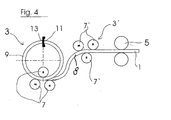
- FIG. 4 shows a modification of the stage I. in FIG. 2 , this modification being that between the feeder 5 and the roll bending machine 3 a Vorbiegestation 3 'is interposed, which provides the drawn strip strand 1 with a curvature (at 8), which is opposite to the curvature, which then the strip strand in the roll plate machine 3 learns.
- the respective length of the strip strand 1 is successively bent around in opposite directions, so that it finally forms the ring turns 9.
- the pre-bending station 3 ' is preferably a roller bending station with bending rollers 7'.
- the drawn-in strip strand 1 preferably has a rectangular cross-section.
- the mutual bending in the stations 3 'and 3 of the respective strip strand sections serves to counteract a wedge-forming tendency of the strip strand in the roll bending machine 3 by a substantially complementary wedge-forming tendency in the prebending station 3' compensating, so that the ring winding 9 again has a rectangular cross-section.
- FIG. 4 thus shows a measure for the efficient production of flat rings with plane-parallel plane faces.
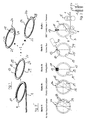
- FIG. 2 the production of an internally toothed clutch plate 2a (inner plate 2a) is illustrated.
- an externally toothed clutch plate, as in FIG. 1 represented and designated 2b, are produced, wherein the contouring of the toothing 18 takes place on the outer circumference 29 of the ring 15.
- FIG. 1 shows only the results of stages I., III. and IV. the FIG. 2 and to demonstrate that from the ring 15 either an internally toothed clutch plate 2a or an externally toothed clutch plate 2b by appropriate contour shaping of the toothing 18 on the inner circumference or on Outer circumference of the ring 15 can be made.
Landscapes
- Engineering & Computer Science (AREA)
- Mechanical Engineering (AREA)
- General Engineering & Computer Science (AREA)
- Mechanical Operated Clutches (AREA)
- Laser Beam Processing (AREA)
- Punching Or Piercing (AREA)
- Wire Processing (AREA)
Applications Claiming Priority (1)
| Application Number | Priority Date | Filing Date | Title |
|---|---|---|---|
| DE102011080927A DE102011080927A1 (de) | 2011-08-12 | 2011-08-12 | Verfahren und Vorrichtung zur Herstellung von ringförmigen Kupplungslamellen mit Verzahnung |
Publications (2)
| Publication Number | Publication Date |
|---|---|
| EP2556905A2 true EP2556905A2 (fr) | 2013-02-13 |
| EP2556905A3 EP2556905A3 (fr) | 2013-08-21 |
Family
ID=46581763
Family Applications (1)
| Application Number | Title | Priority Date | Filing Date |
|---|---|---|---|
| EP12176135.7A Withdrawn EP2556905A3 (fr) | 2011-08-12 | 2012-07-12 | Procédé et dispositif destinés à la fabrication de lamelles d'accouplement annulaires et dentées |
Country Status (2)
| Country | Link |
|---|---|
| EP (1) | EP2556905A3 (fr) |
| DE (1) | DE102011080927A1 (fr) |
Cited By (6)
| Publication number | Priority date | Publication date | Assignee | Title |
|---|---|---|---|---|
| JP2016129890A (ja) * | 2015-01-12 | 2016-07-21 | 株式会社タイガーサッシュ製作所 | リング状部材の製造方法 |
| EP3301795A1 (fr) * | 2016-09-30 | 2018-04-04 | Wieland-Werke AG | Procédé de fabrication d'une bague de court-circuit |
| CN109482015A (zh) * | 2017-09-11 | 2019-03-19 | 江苏中豪神庞科技有限公司 | 一种人防专用过滤吸收器用接头圆环 |
| WO2020207878A1 (fr) * | 2019-04-08 | 2020-10-15 | Zf Friedrichshafen Ag | Disque d'embrayage pour embrayage à disques, embrayage à disques comprenant le disque d'embrayage et procédé de fabrication du disque d'embrayage |
| EP3769901A1 (fr) * | 2019-07-24 | 2021-01-27 | Wilh. Kämper GmbH u. Co. KG | Procédé et dispositif de fabrication de bagues soudées |
| CN113042978A (zh) * | 2021-03-29 | 2021-06-29 | 成都腾达模具有限公司 | 一种格架条带加工方法 |
Families Citing this family (2)
| Publication number | Priority date | Publication date | Assignee | Title |
|---|---|---|---|---|
| DE102017120991A1 (de) | 2017-09-12 | 2019-03-14 | Schaeffler Technologies AG & Co. KG | Reibplatte und Herstellungsverfahren für eine solche Reibplatte |
| CN111215493B (zh) * | 2019-07-02 | 2020-12-29 | 西安交通大学 | 齿链、齿条与齿链啮合式三辊卷弯成形大直径齿轮的方式 |
Family Cites Families (4)
| Publication number | Priority date | Publication date | Assignee | Title |
|---|---|---|---|---|
| DE2159194A1 (de) * | 1971-11-30 | 1973-06-07 | Zahnradfabrik Friedrichshafen | Verfahren zum herstellen kreisringfoermiger reibscheiben fuer reibungskupplungen |
| JPH0763791B2 (ja) * | 1990-10-15 | 1995-07-12 | 本田技研工業株式会社 | クラッチディスク芯板の製造方法 |
| JP3598584B2 (ja) * | 1995-05-01 | 2004-12-08 | アイシン精機株式会社 | 内周部に凹凸部を有する円板状リングの製造方法 |
| CA2225097A1 (fr) * | 1998-01-28 | 1999-07-28 | Germain Harbec | Methode de fabrication d'un corps en tole incurve, et ce meme corps en tole incurve |
-
2011
- 2011-08-12 DE DE102011080927A patent/DE102011080927A1/de not_active Withdrawn
-
2012
- 2012-07-12 EP EP12176135.7A patent/EP2556905A3/fr not_active Withdrawn
Non-Patent Citations (1)
| Title |
|---|
| None |
Cited By (8)
| Publication number | Priority date | Publication date | Assignee | Title |
|---|---|---|---|---|
| JP2016129890A (ja) * | 2015-01-12 | 2016-07-21 | 株式会社タイガーサッシュ製作所 | リング状部材の製造方法 |
| EP3301795A1 (fr) * | 2016-09-30 | 2018-04-04 | Wieland-Werke AG | Procédé de fabrication d'une bague de court-circuit |
| CN107888036A (zh) * | 2016-09-30 | 2018-04-06 | 威兰德-沃克公开股份有限公司 | 短路环的制造方法 |
| CN109482015A (zh) * | 2017-09-11 | 2019-03-19 | 江苏中豪神庞科技有限公司 | 一种人防专用过滤吸收器用接头圆环 |
| WO2020207878A1 (fr) * | 2019-04-08 | 2020-10-15 | Zf Friedrichshafen Ag | Disque d'embrayage pour embrayage à disques, embrayage à disques comprenant le disque d'embrayage et procédé de fabrication du disque d'embrayage |
| CN113646553A (zh) * | 2019-04-08 | 2021-11-12 | 采埃孚股份公司 | 用于多盘式离合器的盘、具有盘的多盘式离合器及用于生产盘的方法 |
| EP3769901A1 (fr) * | 2019-07-24 | 2021-01-27 | Wilh. Kämper GmbH u. Co. KG | Procédé et dispositif de fabrication de bagues soudées |
| CN113042978A (zh) * | 2021-03-29 | 2021-06-29 | 成都腾达模具有限公司 | 一种格架条带加工方法 |
Also Published As
| Publication number | Publication date |
|---|---|
| EP2556905A3 (fr) | 2013-08-21 |
| DE102011080927A1 (de) | 2013-02-14 |
Similar Documents
| Publication | Publication Date | Title |
|---|---|---|
| EP2556905A2 (fr) | Procédé et dispositif destinés à la fabrication de lamelles d'accouplement annulaires et dentées | |
| DE19861391B4 (de) | Verfahren zum Formen einer Nabenscheibe und Drückrolle zur Verwendung beim Formen einer Nabenscheibe | |
| EP0193589B1 (fr) | Appareil et procédé pour produire les douilles de serrage pour tuyaux | |
| WO2014089594A1 (fr) | Procédé de réalisation d'une bande de matière continue | |
| EP1108483A2 (fr) | Procédé et dispositif pour le fluotournage | |
| DE102010028797A1 (de) | Verfahren und Vorrichtung zur Herstellung von Dichtringen | |
| DE102013113418B4 (de) | Verfahren zum Herstellen eines Statorkerns für drehende elektrische Maschinen | |
| WO2009146679A1 (fr) | Procédé de fabrication d'un élément de cage pour une cage de roulement et cage de roulement | |
| DE102010028280A1 (de) | Verfahren zur Herstellung von Stanzteilen und Vorrichtung | |
| DE102010046808B4 (de) | Verfahren und Einrichtung zum Herstellen eines Führungssegmentes für Pendelrollenlager oder dergleichen | |
| DE19915027A1 (de) | Getriebeteil und Verfahren zum Formen eines Getriebeteils | |
| EP3194091B1 (fr) | Procédé de fabrication d'un ressort à ruban et dispositif de pliage pour sa fabrication | |
| DE102006045753A1 (de) | Verfahren zum Herstellen eines ringförmigen Komponententeils, Pressform zur Verwendung bei einem solchen Verfahren und damit hergestelltes Komponententeil | |
| DE4345483A1 (de) | Verfahren zur Herstellung einer Schraubenfeder | |
| EP1909990B1 (fr) | Procede et dispositif pour realiser des anneaux metalliques | |
| DE102024111172A1 (de) | Verfahren und Vorrichtung zum Herstellen eines Statorkörpers einer Axialfluss-maschine, und Axialflussmaschine | |
| DE6941163U (de) | Tellerfeder und vorrichtung zu ihrer herstellung | |
| DE4032424A1 (de) | Herstellvorrichtung fuer gefalzte rohre | |
| EP2177286B1 (fr) | Dispositif de fabrication d'un panier d'embrayage, en particulier d'un double embrayage, et dispositif de cintrage | |
| DE102005031437A1 (de) | Vorrichtung zum Umformen eines bandförmigen Werkstückes | |
| DE102010053720A1 (de) | Verfahren zur Herstellung eines Kupplungskörpers | |
| DE102016007550B4 (de) | Verfahren und Vorrichtung zur Reduzierung einer Ovalität eines Konstruktionselements mit einem im Wesentlichen kreisringförmigen Querschnitt | |
| DE102014115426A1 (de) | Vorrichtung und Verfahren zum kontinuierlichen voranschreitenden Umformen von Metallbändern zu einem Profil mit längsveränderlichem Querschnitt | |
| DE102012212717A1 (de) | Rollbiegeverfahren und -vorrichtung | |
| DE102009056514A1 (de) | Walzverfahren und Walzvorrichtung zum Herstellen eines Metallbandes mit einer über seine Breite variierenden Dicke |
Legal Events
| Date | Code | Title | Description |
|---|---|---|---|
| PUAI | Public reference made under article 153(3) epc to a published international application that has entered the european phase |
Free format text: ORIGINAL CODE: 0009012 |
|
| AK | Designated contracting states |
Kind code of ref document: A2 Designated state(s): AL AT BE BG CH CY CZ DE DK EE ES FI FR GB GR HR HU IE IS IT LI LT LU LV MC MK MT NL NO PL PT RO RS SE SI SK SM TR |
|
| AX | Request for extension of the european patent |
Extension state: BA ME |
|
| PUAL | Search report despatched |
Free format text: ORIGINAL CODE: 0009013 |
|
| AK | Designated contracting states |
Kind code of ref document: A3 Designated state(s): AL AT BE BG CH CY CZ DE DK EE ES FI FR GB GR HR HU IE IS IT LI LT LU LV MC MK MT NL NO PL PT RO RS SE SI SK SM TR |
|
| AX | Request for extension of the european patent |
Extension state: BA ME |
|
| RIC1 | Information provided on ipc code assigned before grant |
Ipc: B21D 11/06 20060101ALI20130712BHEP Ipc: B21D 7/08 20060101ALI20130712BHEP Ipc: B21D 53/16 20060101AFI20130712BHEP Ipc: B21D 53/84 20060101ALI20130712BHEP Ipc: F16D 13/64 20060101ALI20130712BHEP |
|
| STAA | Information on the status of an ep patent application or granted ep patent |
Free format text: STATUS: THE APPLICATION IS DEEMED TO BE WITHDRAWN |
|
| 18D | Application deemed to be withdrawn |
Effective date: 20140222 |