EP2557016A2 - Articulation à support de roue pour un véhicule sur rail - Google Patents
Articulation à support de roue pour un véhicule sur rail Download PDFInfo
- Publication number
- EP2557016A2 EP2557016A2 EP20120171799 EP12171799A EP2557016A2 EP 2557016 A2 EP2557016 A2 EP 2557016A2 EP 20120171799 EP20120171799 EP 20120171799 EP 12171799 A EP12171799 A EP 12171799A EP 2557016 A2 EP2557016 A2 EP 2557016A2
- Authority
- EP
- European Patent Office
- Prior art keywords
- bolt
- receptacle
- bogie frame
- radträgeranlenkung
- spring element
- Prior art date
- Legal status (The legal status is an assumption and is not a legal conclusion. Google has not performed a legal analysis and makes no representation as to the accuracy of the status listed.)
- Granted
Links
Images


Classifications
-
- B—PERFORMING OPERATIONS; TRANSPORTING
- B61—RAILWAYS
- B61F—RAIL VEHICLE SUSPENSIONS, e.g. UNDERFRAMES, BOGIES OR ARRANGEMENTS OF WHEEL AXLES; RAIL VEHICLES FOR USE ON TRACKS OF DIFFERENT WIDTH; PREVENTING DERAILING OF RAIL VEHICLES; WHEEL GUARDS, OBSTRUCTION REMOVERS OR THE LIKE FOR RAIL VEHICLES
- B61F5/00—Constructional details of bogies; Connections between bogies and vehicle underframes; Arrangements or devices for adjusting or allowing self-adjustment of wheel axles or bogies when rounding curves
- B61F5/26—Mounting or securing axle-boxes in vehicle or bogie underframes
- B61F5/30—Axle-boxes mounted for movement under spring control in vehicle or bogie underframes
-
- B—PERFORMING OPERATIONS; TRANSPORTING
- B61—RAILWAYS
- B61F—RAIL VEHICLE SUSPENSIONS, e.g. UNDERFRAMES, BOGIES OR ARRANGEMENTS OF WHEEL AXLES; RAIL VEHICLES FOR USE ON TRACKS OF DIFFERENT WIDTH; PREVENTING DERAILING OF RAIL VEHICLES; WHEEL GUARDS, OBSTRUCTION REMOVERS OR THE LIKE FOR RAIL VEHICLES
- B61F5/00—Constructional details of bogies; Connections between bogies and vehicle underframes; Arrangements or devices for adjusting or allowing self-adjustment of wheel axles or bogies when rounding curves
- B61F5/26—Mounting or securing axle-boxes in vehicle or bogie underframes
- B61F5/30—Axle-boxes mounted for movement under spring control in vehicle or bogie underframes
- B61F5/32—Guides, e.g. plates, for axle-boxes
- B61F5/325—The guiding device including swinging arms or the like to ensure the parallelism of the axles
-
- B—PERFORMING OPERATIONS; TRANSPORTING
- B61—RAILWAYS
- B61F—RAIL VEHICLE SUSPENSIONS, e.g. UNDERFRAMES, BOGIES OR ARRANGEMENTS OF WHEEL AXLES; RAIL VEHICLES FOR USE ON TRACKS OF DIFFERENT WIDTH; PREVENTING DERAILING OF RAIL VEHICLES; WHEEL GUARDS, OBSTRUCTION REMOVERS OR THE LIKE FOR RAIL VEHICLES
- B61F5/00—Constructional details of bogies; Connections between bogies and vehicle underframes; Arrangements or devices for adjusting or allowing self-adjustment of wheel axles or bogies when rounding curves
- B61F5/50—Other details
- B61F5/52—Bogie frames
Definitions
- the invention relates to a Radffyanlenkung for a rail vehicle with a bogie frame, comprising a wheel set comprising at least one wheel and the wheel holding wheel carrier, wherein the wheel carrier is provided on the one hand with a rocker which is pivotally connected via a bolt connection to the bogie frame, and another is resiliently connected via a spring element to the bogie frame, wherein the bolt connection comprises a bolt which is guided by a receptacle in the rocker and at least one receptacle in the bogie frame. Furthermore, the invention relates to a rail vehicle with such Raditatianlenkung.
- the Radreteanlenkung also called Radsatzanlenkung
- a rail vehicle is used to connect the wheels of a wheelset with the bogie frame movable and resilient.
- the wheel held by the wheel carrier is pivotally connected to the bogie frame via a rocker connected to the wheel carrier.
- the wheel on the wheel is also resilient by a so-called primary spring with the bogie frame, that is elastic, connected.
- the primary spring is typically a compression spring which absorbs relative movement between the bogie frame and the wheel carrier to thereby increase vehicle handling and comfort for the passengers.
- a rail vehicle usually still has a so-called secondary spring, which between the bogie frame and the Car body of the rail vehicle is arranged and serves to a further comfort increase.
- the rocker is pivotally mounted by means of a transversely extending bolt on the bogie frame.
- Transverse direction is the horizontal direction transverse to the direction of travel or longitudinal direction, which also runs parallel to the wheel axis.
- the bolt is mounted in a receptacle in the bogie frame in a press fit, whereby a secure hold of the bolt and ultimately the wheelset holding the swingarm is to be ensured.
- the previously derived and indicated object is according to a first teaching of the present invention in a Radffyanlenkung for a rail vehicle with a bogie frame, with a set of wheels containing at least one wheel and the wheel holding the wheel carrier, wherein the wheel carrier is provided on the one hand with a rocker is pivotally connected via a bolt connection with the bogie frame, and on the other hand via a spring element is resiliently connected to the bogie frame, wherein the bolt connection a bolt, for example a Metal bolt, which is guided by a receptacle in the rocker, in particular a receptacle of a bushing inserted into the rocker receptacle, for example rubber-metal bushing, and at least one receptacle in the bogie frame, achieved in that the bolt connection - meaning the connection between the bolt and at least one of the receptacles - has play and the effective direction of the spring element extends obliquely to the horizontal and vertical, such that in the pressurized state of the spring element
- the abovementioned spring element is, in particular, a compression spring, preferably a compression spring of a primary suspension, that is to say a suspension between the bogie frame and the wheel carrier.
- the bolt connection in particular the connection between the bolt and the at least one receptacle in the bogie frame and / or the connection between the bolt and the receptacle in the rocker or, if a socket, for example rubber-metal bushing, inserted in the rocker receptacle is, the connection between the bolt and the receptacle in this socket, afflicted with play, the bolt for disassembling the rocker, when the bolt is unloaded, can easily move out of the or recordings.
- a socket for example rubber-metal bushing
- the direction of action of the spring element meaning the direction of the spring travel or the direction in which the spring element springs - chosen so that the spring element under load pushes the wheel and the rocker from the bogie frame, with the result that the Swing also corresponding to the bolt of the bolt connection in this direction, that is, the direction away from the bogie frame, loaded.
- the bolt is thereby pressed despite the game-afflicted connection or storage against the edge of the respective recording and thereby fixed.
- the bolt In the pressurized state of the spring element, which is constantly given in the ready state of the rail vehicle by the vertical load of the car body, the bolt is thus positively inserted into the respective receptacle in the bogie frame and / or in the receptacle in the rocker or the said in the swing seat Socket pressed. If the spring element is relieved, for example, by the rail vehicle being jacked up, according to the invention the pin is also relieved and can easily be removed.
- the rocker and possibly the wheel carrier can then also be dismantled without further ado.
- the rocker can force or with the rest of the wheel be cohesively connected or be made in one piece with the rest of the wheel.
- the bolt connection has a vertical and / or horizontal clearance between the bolt and the receptacle, in particular the at least one receptacle in the bogie frame and / or the swing receptacle or socket receptacle, for example, rubber-metal socket receptacle on.
- the bolt can be easily removed when it is not loaded.
- connection both the connection between the bolt and rocker or in the presence of a jack inserted into the rocker seat, for example rubber-metal bushing, the connection between the bolt and bushing and the connection between bolts and Bogie frame is meant.
- both the connection between the bolt and bogie frame, that is between the bolt and the corresponding at least one receptacle in the bogie frame, as well as the connection between the bolt and rocker, including in the case of the presence of a socket (for example rubber Metal bushing) in the swing receptacle and the connection between the bolt and socket receptacle (for example, rubber-metal socket receptacle) is understood, is subject to play, in particular the bolt in the pressurized state of the spring element against the at least one receptacle in the bogie frame and against the recording in the rocker, in the presence of said socket (for example, rubber-metal socket) So against the inclusion in said socket, is pressed and can be removed in the unloaded state by the existing game and the reversed positive engagement of said recording.
- a socket for example rubber Metal bushing
- the bolt extends in the horizontal, ie in a longitudinal direction (direction of travel) extending plane.
- the bolt extends parallel to the axis of rotation of the at least one wheel, which axis of rotation also extends in the horizontal.
- a thus extending bolt can be particularly effectively loaded by pressurizing the spring element by the swinging away from the bogie frame rocker and thus in a form fit within the respective receptacle in the bogie frame and / or in the rocker or in the socket, for example rubber-metal socket brought become.
- the bolt in a section transverse to the longitudinal axis of the bolt, an irregularly extending outer contour.
- the receptacle in particular the at least one receptacle in the bogie frame and / or the receptacle in the rocker, or in the presence of such, in the socket, for example rubber-metal bush, in a section transverse to the longitudinal axis of Bolzens, having an uneven inner contour.
- Uneven running in the sense of the present invention means that the respective contour does not have the same distance from the bolt longitudinal axis at every point, that is, the contour is not round.
- Such an outer and inner contour has the advantage that the bolt under load, in particular under the influence of a transmitted from the rocker torque, not readily rotates in the respective recording.
- a rotational movement of the bolt relative to the inner surface of the respective receptacle would on the one hand lead to a wear of recording and / or bolts and on the other hand also bear the risk of unwanted sideways or axial movement of the bolt.
- the outer contour and / or inner contour preferably has at least one corner, preferably three or more corners.
- a bolt, which has an outer contour with, for example, four corners in cross-section to the longitudinal axis of the bolt is a square bolt. In principle, however, bolts with even more corners in the outer contour are conceivable.
- the bolt head of the bolt may have a polygonal cross-section with the aforementioned number of corners, with respect to a section transverse to the longitudinal axis of the bolt.
- the bolt is a hollow bolt.
- the hollow bolt is formed in particular by an axial bore extending at least through the bolt shank and possibly through the bolt head.
- Such a hollow bolt has a relatively low weight and can be fixed in the axial direction with simple means, for example, by a screw is passed through the bore.
- a rubber-metal bushing backlash-free and rotationally fixed, in particular in a press fit is inserted, wherein in the Rubber-metal bush, that is, in the receptacle of the inner sleeve member, so the Buchsenauge, the bolt is inserted.
- the bolt is in the said receptacle of the rubber-metal bushing or the inner bushing element as mentioned also used play, so that it interacts in the pressurized state of the spring element on the contact side play and positive fit with the receptacle and on the contact side facing away from the bolt connection is subject to play.
- a rubber-metal bushing is understood to mean a component which consists of two nested cylinders, in particular metal cylinders, wherein a gap existing between the outer peripheral surface of the inner cylinder and the inner peripheral surface of the outer cylinder is secured with a resilient plastic sleeve. or rubber compound is filled.
- the elastic mass is firmly connected to the surface of the inner and outer cylinder, so that forces and moments can be transmitted from both the outer cylinder and the inner cylinder to the elastic mass.
- Such a rubber-metal bush has the advantage that the pivoting movements of the rocker are not or at least not completely transferred to the bolt.
- the bolt is thus even better protected against wear and unintended axial movements.
- the pressurized state of the spring element but the necessary force is still exerted on the bolt in the direction of the contact surface of the respective recording, so that it sits positively in the respective recording.
- no load acts on the connection between the bolt and rubber-metal socket, so that the bolt also from the corresponding receptacle in the rubber-metal socket, the Socket eye or recording in the inner socket element, can be moved out.
- the at least one receptacle in the bogie frame of a receiving socket for example, a metal bushing is formed, which is free of play and rotationally fixed, in particular in a press fit, connected to the rest of the bogie frame.
- this receiving bush is shrunk into the recess provided for this purpose.
- the receiving socket thus forms part of the bogie frame which receives the bolt. In this way, an ideal material pairing can be selected in the contact area between the bolt and the receptacle.
- the bolt In the pressurized state of the spring element, the bolt is then pressed against the inner surface of the receiving socket, whereby in the region in which the bolt contacts the receiving socket, that is on the contact side, the bolt connection is play or form-fitting, whereas on the side facing away contact play between bolt and receiving socket is present.
- the bolt is covered against its insertion direction of a cover plate.
- Insertion direction means the direction in which the bolt is guided in the transverse direction through the receptacles to connect the rocker to the bogie frame.
- a cover plate serves to secure the bolt in the axial direction or to fix.
- the longitudinal axis of the bolt is in the same horizontal plane as the axis of rotation of the at least one wheel. This results in the load case to an ideal application of force to the bolt connection. It is preferred if the bolt connection and the spring element are arranged on the same side of a plane passing through the axis of rotation of the wheel vertical plane. It is also preferred that the direction of action of the spring element or the spring axis intersects the axis of rotation of the at least one wheel, that extends through the axis of the wheel.
- the angle between the effective direction of the spring element (the spring axis) and the horizontal in a range of 0 to 70 °, preferably from 20 to 60 °, particularly preferably from 30 to 50 °, the angle is ideally 45th ° is.
- the object is further achieved by a rail vehicle with a Radchtanlenkung as previously described.
- the Radanlenkung be part of a bogie of a rail vehicle.
- the spring element is a compression spring, in particular a compression spring of a primary suspension of the rail vehicle.
- the weight of the car body is automatically used to push the rocker and the wheel carrier of the bogie frame and thus to apply the bolt in the direction of the contact surface of the respective recording.
- the spring element in the operational state of the rail vehicle, is permanently pressurized and / or the bolt is constantly against the edge of the receptacle, in particular the at least one receptacle in the bogie frame and / or the receptacle in the Swing or, in the presence of such a socket, the receptacle in the socket, for example, rubber-metal socket, is pressed.
- ready state a state is meant in which the weight of the car body rests on the bogie frame and accordingly the spring element is pressurized.
- a relieved state of the spring element can be caused by the fact that the rail vehicle is jacked example.
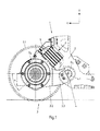
- Fig. 1 is a Radreteanschung 1 a bogie of a rail vehicle shown.
- the bogie frame 2 the wheel 3 and a spring element 5 is shown in the form of a primary spring.
- the wheelset 3 contains a plurality of wheels 3.1, of which only one is shown here, as well as a wheel carrier 3.2 holding this 3.2.
- the wheel carrier 3.2 is connected to a rocker 3.3, which is pivotally connected via a bolt connection 4 with the bogie frame 2.
- the wheel carrier 3.2 is also connected to the bogie frame 2 via said primary spring 5, which is a compression spring here.
- the bolt connection 4 has a bolt 4.1, here a metal bolt, and a plurality of receptacles 2.1 and 3.31 or 6.11. As in Fig. 2 can be seen, the bolt extends in the direction of insertion E B first by a left bogie frame recording 2.1 in the bogie frame 2, then by a swing 3.31 the rocker 3.3, more precisely by a recording 6.11 in a rubber-metal socket 6, and finally by a right bogie frame recording 2.1 of the bogie frame 2.
- the left and right Bogie frame receiver 2.1 is formed in each case by a receiving socket 2.2, which also consists of metal.
- the rocker 3.3 is connected via the rubber-metal socket 6 with the bolt 4.1.
- the rubber-metal bushing 6 has an inner bushing element 6.1 made of metal, a middle bushing element 6.2 made of rubber and an outer bushing element 6.3 made of metal.
- the inner and outer bushing elements 6.1 and 6.3 are cylindrical in shape.
- the bolt connection 4 is in the region of the connection between bolt 4.1 and bogie frame receptacle 2.1 as well as in the area of the connection between bolt 4.1 and rocker seat 3.31 and bushing receptacle 6.11 afflicted.
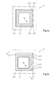
- This is schematically in Fig. 4 for the bolt connection 4 between bolt 4.1 and bogie frame 2 shown.
- Fig. 4a shows an unloaded and Fig. 4b ) a loaded or pressurized state.
- the loaded state is achieved as follows:
- the effective direction F of the spring element 5 extends obliquely to the horizontal H and vertical V, such that in the pressurized state of the spring element 5, that is, if the vertical load of the (not shown) car body of the rail vehicle on the spring element 5 acts, the wheel 3.2 is pressed together with the rocker 3.3 from the bogie frame 2.
- This pressure also acts on the rocker connection 4 via the rocker arm and causes the bolt 4.1 against the edge of the receptacle 2.1 of the bogie frame 2 and correspondingly against the inner surface of the inner bushing element 6.1 of the rubber-metal bushing 6 is pressed.
- the bolt connection 4 both a vertical play Sv and a horizontal play SH . This applies both to the pressurized state and the unloaded state of the spring element 5, both for the bolt connection 4 between bolt 4.1 and bogie frame 2 and for the bolt connection 4 between bolt 4.1 and rocker 3.3, that is between bolt 4.1 and rubber.
- FIGS. 1 to 3 clearly show the bolt 4.1 runs in the horizontal H, namely parallel to the axis of rotation D R of the wheel 3.1.
- the longitudinal axis X B of the bolt 4.1 and the thus identical rotation axis D S of the rocker 3.3 lies in the same horizontal plane as the axis of rotation D R of the wheel 3.1.
- Bolt 4 and spring element 5 are also arranged on the same side of a through the axis of rotation D R of the wheel 3.1 extending vertical V.
- the effective direction F of the spring element 5 intersects the axis of rotation D R of the wheel 3.1.
- the angle ⁇ between the effective direction F of the spring element 5 and the horizontal H is here at 45 °.
- the bolt 4.1 in the present case to a hollow bolt, although according to the invention also bolts of solid material can be used.
- the bolt 4.1 is here designed as a square bolt, wherein the receptacle 2.1 or receiving bushing 2.2 and the receptacle 6.11 of the rubber-metal bushing 6 also has a quadrangular inner cross-section.
- a cover plate 7 is shown, which covers the bolt 4.1 against its insertion direction E B and fixed.
Landscapes
- Engineering & Computer Science (AREA)
- Mechanical Engineering (AREA)
- Vibration Prevention Devices (AREA)
- Vehicle Body Suspensions (AREA)
- Springs (AREA)
- Body Structure For Vehicles (AREA)
- Handcart (AREA)
Priority Applications (1)
| Application Number | Priority Date | Filing Date | Title |
|---|---|---|---|
| PL12171799T PL2557016T3 (pl) | 2011-08-12 | 2012-06-13 | Połączenie przegubowe wspornika osadzenia koła dla pojazdu szynowego |
Applications Claiming Priority (1)
| Application Number | Priority Date | Filing Date | Title |
|---|---|---|---|
| DE201110110090 DE102011110090A1 (de) | 2011-08-12 | 2011-08-12 | Radträgeranlenkung für ein Schienenfahrzeug |
Publications (3)
| Publication Number | Publication Date |
|---|---|
| EP2557016A2 true EP2557016A2 (fr) | 2013-02-13 |
| EP2557016A3 EP2557016A3 (fr) | 2013-08-14 |
| EP2557016B1 EP2557016B1 (fr) | 2017-04-05 |
Family
ID=46172725
Family Applications (2)
| Application Number | Title | Priority Date | Filing Date |
|---|---|---|---|
| EP12170076.9A Active EP2557015B1 (fr) | 2011-08-12 | 2012-05-30 | Unité de train de roulement pour un véhicule ferroviaire |
| EP12171799.5A Active EP2557016B1 (fr) | 2011-08-12 | 2012-06-13 | Articulation à support de roue pour un véhicule sur rail |
Family Applications Before (1)
| Application Number | Title | Priority Date | Filing Date |
|---|---|---|---|
| EP12170076.9A Active EP2557015B1 (fr) | 2011-08-12 | 2012-05-30 | Unité de train de roulement pour un véhicule ferroviaire |
Country Status (11)
| Country | Link |
|---|---|
| US (1) | US9718484B2 (fr) |
| EP (2) | EP2557015B1 (fr) |
| CN (1) | CN102951169B (fr) |
| AU (1) | AU2012209001B2 (fr) |
| BR (1) | BR112014029462A2 (fr) |
| CA (1) | CA2784534C (fr) |
| DE (1) | DE102011110090A1 (fr) |
| ES (1) | ES2627794T3 (fr) |
| LT (1) | LT2557016T (fr) |
| PL (1) | PL2557016T3 (fr) |
| PT (1) | PT2557016T (fr) |
Cited By (2)
| Publication number | Priority date | Publication date | Assignee | Title |
|---|---|---|---|---|
| WO2016083009A1 (fr) * | 2014-11-27 | 2016-06-02 | Siemens Ag Österreich | Guide d'essieu monté pour véhicule ferroviaire |
| AT524445B1 (de) * | 2021-03-29 | 2022-06-15 | Siemens Mobility Austria Gmbh | Führungsvorrichtung für Fahrwerke, Fahrwerk und Verfahren zur Montage einer Führungsvorrichtung in ein Fahrwerk |
Families Citing this family (15)
| Publication number | Priority date | Publication date | Assignee | Title |
|---|---|---|---|---|
| DE102011110090A1 (de) | 2011-08-12 | 2013-02-14 | Bombardier Transportation Gmbh | Radträgeranlenkung für ein Schienenfahrzeug |
| US9352757B2 (en) * | 2012-04-06 | 2016-05-31 | Kawasaki Jukogyo Kabushiki Kaisha | Railcar bogie |
| EP2860081B1 (fr) * | 2012-04-06 | 2018-05-02 | Kawasaki Jukogyo Kabushiki Kaisha | Bogie de wagon |
| JP5765292B2 (ja) * | 2012-05-21 | 2015-08-19 | 新日鐵住金株式会社 | 鉄道車両の台車枠 |
| ES2880707T3 (es) | 2012-05-30 | 2021-11-25 | Bombardier Transp Gmbh | Bastidor de tren de rodaje para vehículo ferroviario |
| CN103448743A (zh) | 2012-05-30 | 2013-12-18 | 庞巴迪运输有限公司 | 轨道车辆的运行装置单元 |
| EP2669137B1 (fr) | 2012-05-30 | 2020-07-08 | Bombardier Transportation GmbH | Dispositif à ressort pour véhicule ferroviaire |
| EP2669136B1 (fr) | 2012-05-30 | 2020-01-01 | Bombardier Transportation GmbH | Unité de véhicule ferroviaire |
| JP5772761B2 (ja) * | 2012-08-13 | 2015-09-02 | 新日鐵住金株式会社 | 鉄道車両の台車枠 |
| JP6110669B2 (ja) * | 2013-01-10 | 2017-04-05 | 川崎重工業株式会社 | 鉄道車両用台車及びそれを備えた鉄道車両 |
| FR3049253B1 (fr) * | 2016-03-25 | 2018-04-20 | Alstom Transport Technologies | Bogie de vehicule ferroviaire comprenant un chassis abaisse |
| ES2861726T3 (es) * | 2018-05-25 | 2021-10-06 | Bombardier Transp Gmbh | Bastidor de tren de rodaje para vehículo ferroviario |
| DE102018210880A1 (de) * | 2018-07-03 | 2020-01-09 | Siemens Aktiengesellschaft | Radsatzzwischenrahmen für ein Schienenfahrzeug |
| CN112298252B (zh) * | 2019-08-02 | 2022-04-15 | 中车唐山机车车辆有限公司 | 一种转向架 |
| DE102019216088A1 (de) | 2019-10-18 | 2021-04-22 | Siemens Mobility GmbH | Anordnung zur Positionierung eines Rads eines Schienenfahrzeugs |
Family Cites Families (20)
| Publication number | Priority date | Publication date | Assignee | Title |
|---|---|---|---|---|
| US2197727A (en) * | 1937-04-08 | 1940-04-16 | Budd Edward G Mfg Co | Vehicle |
| FR1253350A (fr) * | 1959-12-30 | 1961-02-10 | Const Du Ct Atel | Bogie perfectionné |
| DE2537172A1 (de) * | 1975-08-21 | 1977-02-24 | Maschf Augsburg Nuernberg Ag | Radsatzfuehrung fuer schnellauffaehige laufwerke von schienenfahrzeugen |
| FR2626540B1 (fr) * | 1988-01-28 | 1990-05-18 | Alsthom Creusot Rail | Suspension primaire de bogie |
| DE4136926A1 (de) | 1991-11-11 | 1993-05-13 | Abb Henschel Waggon Union | Fahrwerk fuer niederflurbahnen |
| DE4214066C2 (de) | 1992-04-29 | 1994-07-14 | Siemens Ag | Fahrwerk für ein Schienenfahrzeug |
| DE4428038C1 (de) * | 1994-08-08 | 1995-08-10 | Siemens Ag | Fahrwerk für ein Schienenfahrzeug |
| CN2515076Y (zh) | 2001-12-28 | 2002-10-09 | 湘潭电机股份有限公司 | 低地板轻轨车拖动转向架 |
| JP2005069393A (ja) * | 2003-08-26 | 2005-03-17 | Daifuku Co Ltd | 締結装置 |
| FR2862935B1 (fr) * | 2003-12-02 | 2006-03-03 | Alstom | Dispositif de liaison souple entre un longeron et une boite d'essieu |
| US7300237B2 (en) * | 2004-11-22 | 2007-11-27 | Inventio Ag | Self-locking bolted fastener |
| DE102006029835A1 (de) | 2006-06-27 | 2008-01-03 | Bombardier Transportation Gmbh | Fahrwerksrahmen eines Schienenfahrzeugs |
| CN2920770Y (zh) * | 2006-07-19 | 2007-07-11 | 中国南车集团眉山车辆厂 | 宽轨焊接转向架 |
| FR2914610A1 (fr) | 2007-04-05 | 2008-10-10 | Alstom Transport Sa | Dispositif de suspension primaire d'un bogie de vehicule ferroviaire |
| DE102007038255A1 (de) | 2007-08-13 | 2009-02-19 | Bombardier Transportation Gmbh | Schienenfahrzeug mit einer Antriebseinrichtung |
| CN201186655Y (zh) * | 2008-04-14 | 2009-01-28 | 南车株洲电力机车有限公司 | 一系悬挂结构 |
| AT507754A1 (de) * | 2008-12-22 | 2010-07-15 | Siemens Ag Oesterreich | Primärfeder |
| FR2946308B1 (fr) | 2009-06-05 | 2011-08-05 | Alstom Transport Sa | Bogie de vehicule ferroviaire articule |
| DE102011110090A1 (de) | 2011-08-12 | 2013-02-14 | Bombardier Transportation Gmbh | Radträgeranlenkung für ein Schienenfahrzeug |
| CN202413825U (zh) | 2011-12-12 | 2012-09-05 | 南车南京浦镇车辆有限公司 | 轮对提吊机构 |
-
2011
- 2011-08-12 DE DE201110110090 patent/DE102011110090A1/de not_active Withdrawn
-
2012
- 2012-05-30 EP EP12170076.9A patent/EP2557015B1/fr active Active
- 2012-06-13 ES ES12171799.5T patent/ES2627794T3/es active Active
- 2012-06-13 PT PT121717995T patent/PT2557016T/pt unknown
- 2012-06-13 LT LTEP12171799.5T patent/LT2557016T/lt unknown
- 2012-06-13 EP EP12171799.5A patent/EP2557016B1/fr active Active
- 2012-06-13 PL PL12171799T patent/PL2557016T3/pl unknown
- 2012-07-30 AU AU2012209001A patent/AU2012209001B2/en active Active
- 2012-08-02 CA CA2784534A patent/CA2784534C/fr active Active
- 2012-08-13 CN CN201210287548.XA patent/CN102951169B/zh active Active
-
2013
- 2013-05-29 BR BR112014029462A patent/BR112014029462A2/pt active Search and Examination
- 2013-05-29 US US14/402,904 patent/US9718484B2/en active Active
Non-Patent Citations (1)
| Title |
|---|
| None |
Cited By (4)
| Publication number | Priority date | Publication date | Assignee | Title |
|---|---|---|---|---|
| WO2016083009A1 (fr) * | 2014-11-27 | 2016-06-02 | Siemens Ag Österreich | Guide d'essieu monté pour véhicule ferroviaire |
| US10625756B2 (en) | 2014-11-27 | 2020-04-21 | Siemens Mobility Austria Gmbh | Wheelset guide for a vehicle |
| AT524445B1 (de) * | 2021-03-29 | 2022-06-15 | Siemens Mobility Austria Gmbh | Führungsvorrichtung für Fahrwerke, Fahrwerk und Verfahren zur Montage einer Führungsvorrichtung in ein Fahrwerk |
| AT524445A4 (de) * | 2021-03-29 | 2022-06-15 | Siemens Mobility Austria Gmbh | Führungsvorrichtung für Fahrwerke, Fahrwerk und Verfahren zur Montage einer Führungsvorrichtung in ein Fahrwerk |
Also Published As
| Publication number | Publication date |
|---|---|
| ES2627794T3 (es) | 2017-07-31 |
| BR112014029462A2 (pt) | 2017-06-27 |
| US9718484B2 (en) | 2017-08-01 |
| EP2557015A3 (fr) | 2013-08-14 |
| US20150107487A1 (en) | 2015-04-23 |
| LT2557016T (lt) | 2017-06-26 |
| PL2557016T3 (pl) | 2017-08-31 |
| CA2784534C (fr) | 2014-10-21 |
| EP2557016B1 (fr) | 2017-04-05 |
| CN102951169A (zh) | 2013-03-06 |
| EP2557015A2 (fr) | 2013-02-13 |
| CA2784534A1 (fr) | 2013-02-12 |
| AU2012209001B2 (en) | 2014-08-28 |
| PT2557016T (pt) | 2017-06-20 |
| AU2012209001A1 (en) | 2013-02-28 |
| EP2557016A3 (fr) | 2013-08-14 |
| EP2557015B1 (fr) | 2020-10-21 |
| CN102951169B (zh) | 2017-11-03 |
| DE102011110090A1 (de) | 2013-02-14 |
Similar Documents
| Publication | Publication Date | Title |
|---|---|---|
| EP2557016B1 (fr) | Articulation à support de roue pour un véhicule sur rail | |
| EP2958761B1 (fr) | Connection entre un bras de suspension de véhicule et une chape. | |
| DE10246428B4 (de) | Richtgelenk für Kuppelstangen | |
| DE102015108277B4 (de) | Bremsvorrichtung für ein Laufwerk einer Einschienenhängebahn | |
| DE102013202792B4 (de) | Verbindungsanordnung zwischen einem radführenden Lenker einer Fahrzeug-Radaufhängung und einem Flansch | |
| DE102009037273A1 (de) | Walzenlagerbefestigung | |
| DE2601648A1 (de) | Kufenanordnung fuer das fahrwerk eines luftfahrzeugs | |
| DE2365798A1 (de) | Gleit/gummitorsions-lagerung zur aufnahme von axialen und radialen kraeften | |
| EP1974150B1 (fr) | Frein à disque | |
| EP2562062B1 (fr) | Dispositif de soutien pour le soutien vertical d'une tige d'embrayage articulée sur la sous-structure d'un châssis d'un véhicule sur rail | |
| EP0999168A2 (fr) | Dispositif de freinage à double action pour ascenseurs ou dispositifs de desserte de rayonnage | |
| DE102018200323B4 (de) | Blattfederanordnung für Kraftfahrzeuge | |
| EP2664576B1 (fr) | Dispositif d'étayage réduisant la force transversale | |
| DE941913C (de) | Zug- und Stossvorrichtung fuer Schienenfahrzeuge mit Mittelpufferkupplung | |
| DE202011050555U1 (de) | Rammpuffer | |
| DE2522255C3 (de) | Befestigungseinrichtung zum Abstützen eines Satteljoches einer Scheibenbremse an einem fahrzeugfesten Bauteil, insbesondere an einem Schienenfahrzeug- oder Drehgestellrahmen | |
| EP2604472B1 (fr) | Plateforme de chargement par levage | |
| DE102014222273A1 (de) | Abstützvorrichtung zum vertikalen Abstützen einer Kupplungsstange kompakter Bauhöhe | |
| DE102015108890A1 (de) | Scheibenbremse | |
| DE1605074B2 (de) | Drehzapfenlager, insbesondere fuer drehgestelle von schienenfahrzeugen | |
| DE534525C (de) | Abfederung fuer Kraftfahrzeuge | |
| DE10304717B4 (de) | Klotzbremseinrichtung für Radsätze eines Drehgestells eines Schienenfahrzeugs | |
| EP3554918B1 (fr) | Articulation pour la liaison articulée d'une barre d'attelage à une caisse de wagon | |
| DE8429553U1 (de) | Kraftfahrzeug mit einem rahmen und einem aufbau | |
| EP3212956A1 (fr) | Étrier de frein en fonte d'un frein à disque |
Legal Events
| Date | Code | Title | Description |
|---|---|---|---|
| PUAI | Public reference made under article 153(3) epc to a published international application that has entered the european phase |
Free format text: ORIGINAL CODE: 0009012 |
|
| AK | Designated contracting states |
Kind code of ref document: A2 Designated state(s): AL AT BE BG CH CY CZ DE DK EE ES FI FR GB GR HR HU IE IS IT LI LT LU LV MC MK MT NL NO PL PT RO RS SE SI SK SM TR |
|
| AX | Request for extension of the european patent |
Extension state: BA ME |
|
| PUAL | Search report despatched |
Free format text: ORIGINAL CODE: 0009013 |
|
| AK | Designated contracting states |
Kind code of ref document: A3 Designated state(s): AL AT BE BG CH CY CZ DE DK EE ES FI FR GB GR HR HU IE IS IT LI LT LU LV MC MK MT NL NO PL PT RO RS SE SI SK SM TR |
|
| AX | Request for extension of the european patent |
Extension state: BA ME |
|
| RIC1 | Information provided on ipc code assigned before grant |
Ipc: B61F 5/32 20060101AFI20130705BHEP |
|
| 17P | Request for examination filed |
Effective date: 20130815 |
|
| 17Q | First examination report despatched |
Effective date: 20131009 |
|
| RBV | Designated contracting states (corrected) |
Designated state(s): AL AT BE BG CH CY CZ DE DK EE ES FI FR GB GR HR HU IE IS IT LI LT LU LV MC MK MT NL NO PL PT RO RS SE SI SK SM TR |
|
| GRAP | Despatch of communication of intention to grant a patent |
Free format text: ORIGINAL CODE: EPIDOSNIGR1 |
|
| INTG | Intention to grant announced |
Effective date: 20161026 |
|
| GRAS | Grant fee paid |
Free format text: ORIGINAL CODE: EPIDOSNIGR3 |
|
| GRAA | (expected) grant |
Free format text: ORIGINAL CODE: 0009210 |
|
| AK | Designated contracting states |
Kind code of ref document: B1 Designated state(s): AL AT BE BG CH CY CZ DE DK EE ES FI FR GB GR HR HU IE IS IT LI LT LU LV MC MK MT NL NO PL PT RO RS SE SI SK SM TR |
|
| REG | Reference to a national code |
Ref country code: GB Ref legal event code: FG4D Free format text: NOT ENGLISH |
|
| REG | Reference to a national code |
Ref country code: CH Ref legal event code: EP |
|
| REG | Reference to a national code |
Ref country code: AT Ref legal event code: REF Ref document number: 881511 Country of ref document: AT Kind code of ref document: T Effective date: 20170415 |
|
| REG | Reference to a national code |
Ref country code: IE Ref legal event code: FG4D Free format text: LANGUAGE OF EP DOCUMENT: GERMAN |
|
| REG | Reference to a national code |
Ref country code: DE Ref legal event code: R096 Ref document number: 502012009950 Country of ref document: DE |
|
| REG | Reference to a national code |
Ref country code: CH Ref legal event code: NV Representative=s name: SCHMAUDER AND PARTNER AG PATENT- UND MARKENANW, CH |
|
| REG | Reference to a national code |
Ref country code: PT Ref legal event code: SC4A Ref document number: 2557016 Country of ref document: PT Date of ref document: 20170620 Kind code of ref document: T Free format text: AVAILABILITY OF NATIONAL TRANSLATION Effective date: 20170607 |
|
| REG | Reference to a national code |
Ref country code: NL Ref legal event code: FP Ref country code: FR Ref legal event code: PLFP Year of fee payment: 6 |
|
| REG | Reference to a national code |
Ref country code: SE Ref legal event code: TRGR |
|
| REG | Reference to a national code |
Ref country code: ES Ref legal event code: FG2A Ref document number: 2627794 Country of ref document: ES Kind code of ref document: T3 Effective date: 20170731 |
|
| PG25 | Lapsed in a contracting state [announced via postgrant information from national office to epo] |
Ref country code: HR Free format text: LAPSE BECAUSE OF FAILURE TO SUBMIT A TRANSLATION OF THE DESCRIPTION OR TO PAY THE FEE WITHIN THE PRESCRIBED TIME-LIMIT Effective date: 20170405 Ref country code: FI Free format text: LAPSE BECAUSE OF FAILURE TO SUBMIT A TRANSLATION OF THE DESCRIPTION OR TO PAY THE FEE WITHIN THE PRESCRIBED TIME-LIMIT Effective date: 20170405 Ref country code: GR Free format text: LAPSE BECAUSE OF FAILURE TO SUBMIT A TRANSLATION OF THE DESCRIPTION OR TO PAY THE FEE WITHIN THE PRESCRIBED TIME-LIMIT Effective date: 20170706 Ref country code: NO Free format text: LAPSE BECAUSE OF FAILURE TO SUBMIT A TRANSLATION OF THE DESCRIPTION OR TO PAY THE FEE WITHIN THE PRESCRIBED TIME-LIMIT Effective date: 20170705 |
|
| PG25 | Lapsed in a contracting state [announced via postgrant information from national office to epo] |
Ref country code: IS Free format text: LAPSE BECAUSE OF FAILURE TO SUBMIT A TRANSLATION OF THE DESCRIPTION OR TO PAY THE FEE WITHIN THE PRESCRIBED TIME-LIMIT Effective date: 20170805 Ref country code: RS Free format text: LAPSE BECAUSE OF FAILURE TO SUBMIT A TRANSLATION OF THE DESCRIPTION OR TO PAY THE FEE WITHIN THE PRESCRIBED TIME-LIMIT Effective date: 20170405 Ref country code: BG Free format text: LAPSE BECAUSE OF FAILURE TO SUBMIT A TRANSLATION OF THE DESCRIPTION OR TO PAY THE FEE WITHIN THE PRESCRIBED TIME-LIMIT Effective date: 20170705 |
|
| REG | Reference to a national code |
Ref country code: DE Ref legal event code: R097 Ref document number: 502012009950 Country of ref document: DE |
|
| PG25 | Lapsed in a contracting state [announced via postgrant information from national office to epo] |
Ref country code: CZ Free format text: LAPSE BECAUSE OF FAILURE TO SUBMIT A TRANSLATION OF THE DESCRIPTION OR TO PAY THE FEE WITHIN THE PRESCRIBED TIME-LIMIT Effective date: 20170405 Ref country code: DK Free format text: LAPSE BECAUSE OF FAILURE TO SUBMIT A TRANSLATION OF THE DESCRIPTION OR TO PAY THE FEE WITHIN THE PRESCRIBED TIME-LIMIT Effective date: 20170405 Ref country code: EE Free format text: LAPSE BECAUSE OF FAILURE TO SUBMIT A TRANSLATION OF THE DESCRIPTION OR TO PAY THE FEE WITHIN THE PRESCRIBED TIME-LIMIT Effective date: 20170405 Ref country code: MC Free format text: LAPSE BECAUSE OF FAILURE TO SUBMIT A TRANSLATION OF THE DESCRIPTION OR TO PAY THE FEE WITHIN THE PRESCRIBED TIME-LIMIT Effective date: 20170405 Ref country code: SK Free format text: LAPSE BECAUSE OF FAILURE TO SUBMIT A TRANSLATION OF THE DESCRIPTION OR TO PAY THE FEE WITHIN THE PRESCRIBED TIME-LIMIT Effective date: 20170405 Ref country code: RO Free format text: LAPSE BECAUSE OF FAILURE TO SUBMIT A TRANSLATION OF THE DESCRIPTION OR TO PAY THE FEE WITHIN THE PRESCRIBED TIME-LIMIT Effective date: 20170405 |
|
| PLBE | No opposition filed within time limit |
Free format text: ORIGINAL CODE: 0009261 |
|
| STAA | Information on the status of an ep patent application or granted ep patent |
Free format text: STATUS: NO OPPOSITION FILED WITHIN TIME LIMIT |
|
| PG25 | Lapsed in a contracting state [announced via postgrant information from national office to epo] |
Ref country code: SM Free format text: LAPSE BECAUSE OF FAILURE TO SUBMIT A TRANSLATION OF THE DESCRIPTION OR TO PAY THE FEE WITHIN THE PRESCRIBED TIME-LIMIT Effective date: 20170405 |
|
| 26N | No opposition filed |
Effective date: 20180108 |
|
| REG | Reference to a national code |
Ref country code: IE Ref legal event code: MM4A |
|
| PG25 | Lapsed in a contracting state [announced via postgrant information from national office to epo] |
Ref country code: IE Free format text: LAPSE BECAUSE OF NON-PAYMENT OF DUE FEES Effective date: 20170613 |
|
| PG25 | Lapsed in a contracting state [announced via postgrant information from national office to epo] |
Ref country code: SI Free format text: LAPSE BECAUSE OF FAILURE TO SUBMIT A TRANSLATION OF THE DESCRIPTION OR TO PAY THE FEE WITHIN THE PRESCRIBED TIME-LIMIT Effective date: 20170405 |
|
| REG | Reference to a national code |
Ref country code: FR Ref legal event code: PLFP Year of fee payment: 7 |
|
| PG25 | Lapsed in a contracting state [announced via postgrant information from national office to epo] |
Ref country code: MT Free format text: LAPSE BECAUSE OF FAILURE TO SUBMIT A TRANSLATION OF THE DESCRIPTION OR TO PAY THE FEE WITHIN THE PRESCRIBED TIME-LIMIT Effective date: 20170405 |
|
| PG25 | Lapsed in a contracting state [announced via postgrant information from national office to epo] |
Ref country code: HU Free format text: LAPSE BECAUSE OF FAILURE TO SUBMIT A TRANSLATION OF THE DESCRIPTION OR TO PAY THE FEE WITHIN THE PRESCRIBED TIME-LIMIT; INVALID AB INITIO Effective date: 20120613 |
|
| PG25 | Lapsed in a contracting state [announced via postgrant information from national office to epo] |
Ref country code: CY Free format text: LAPSE BECAUSE OF NON-PAYMENT OF DUE FEES Effective date: 20170405 |
|
| PG25 | Lapsed in a contracting state [announced via postgrant information from national office to epo] |
Ref country code: MK Free format text: LAPSE BECAUSE OF FAILURE TO SUBMIT A TRANSLATION OF THE DESCRIPTION OR TO PAY THE FEE WITHIN THE PRESCRIBED TIME-LIMIT Effective date: 20170405 |
|
| PG25 | Lapsed in a contracting state [announced via postgrant information from national office to epo] |
Ref country code: AL Free format text: LAPSE BECAUSE OF FAILURE TO SUBMIT A TRANSLATION OF THE DESCRIPTION OR TO PAY THE FEE WITHIN THE PRESCRIBED TIME-LIMIT Effective date: 20170405 |
|
| REG | Reference to a national code |
Ref country code: LU Ref legal event code: PD Owner name: ALSTOM HOLDINGS; FR Free format text: FORMER OWNER: BOMBARDIER TRANSPORTATION GMBH Effective date: 20230825 |
|
| P01 | Opt-out of the competence of the unified patent court (upc) registered |
Effective date: 20230822 |
|
| PGFP | Annual fee paid to national office [announced via postgrant information from national office to epo] |
Ref country code: PL Payment date: 20250606 Year of fee payment: 14 Ref country code: DE Payment date: 20250618 Year of fee payment: 14 |
|
| PGFP | Annual fee paid to national office [announced via postgrant information from national office to epo] |
Ref country code: GB Payment date: 20250618 Year of fee payment: 14 |
|
| PGFP | Annual fee paid to national office [announced via postgrant information from national office to epo] |
Ref country code: LT Payment date: 20250523 Year of fee payment: 14 |
|
| PGFP | Annual fee paid to national office [announced via postgrant information from national office to epo] |
Ref country code: LU Payment date: 20250627 Year of fee payment: 14 Ref country code: NL Payment date: 20250618 Year of fee payment: 14 Ref country code: BE Payment date: 20250618 Year of fee payment: 14 |
|
| PGFP | Annual fee paid to national office [announced via postgrant information from national office to epo] |
Ref country code: PT Payment date: 20250605 Year of fee payment: 14 Ref country code: LV Payment date: 20250612 Year of fee payment: 14 |
|
| PGFP | Annual fee paid to national office [announced via postgrant information from national office to epo] |
Ref country code: FR Payment date: 20250624 Year of fee payment: 14 |
|
| PGFP | Annual fee paid to national office [announced via postgrant information from national office to epo] |
Ref country code: AT Payment date: 20250620 Year of fee payment: 14 |
|
| PGFP | Annual fee paid to national office [announced via postgrant information from national office to epo] |
Ref country code: TR Payment date: 20250610 Year of fee payment: 14 |
|
| PGFP | Annual fee paid to national office [announced via postgrant information from national office to epo] |
Ref country code: SE Payment date: 20250618 Year of fee payment: 14 |
|
| PGFP | Annual fee paid to national office [announced via postgrant information from national office to epo] |
Ref country code: ES Payment date: 20250728 Year of fee payment: 14 |
|
| PGFP | Annual fee paid to national office [announced via postgrant information from national office to epo] |
Ref country code: IT Payment date: 20250624 Year of fee payment: 14 |
|
| PGFP | Annual fee paid to national office [announced via postgrant information from national office to epo] |
Ref country code: CH Payment date: 20250701 Year of fee payment: 14 |
|
| REG | Reference to a national code |
Ref country code: BE Ref legal event code: HC Owner name: ALSTOM TRANSPORTATION GERMANY GMBH; DE Free format text: DETAILS ASSIGNMENT: CHANGE OF OWNER(S), CHANGE OF OWNER(S) NAME; FORMER OWNER NAME: BOMBARDIER TRANSPORTATION GMBH Effective date: 20251016 Ref country code: BE Ref legal event code: PD Owner name: BOMBARDIER TRANSPORTATION GMBH; DE Free format text: DETAILS ASSIGNMENT: CHANGE OF OWNER(S), OTHER; FORMER OWNER NAME: BOMBARDIER TRANSPORTATION GMBH Effective date: 20251016 Ref country code: BE Ref legal event code: PD Owner name: ALSTOM TRANSPORTATION GERMANY GMBH; DE Free format text: DETAILS ASSIGNMENT: CHANGE OF OWNER(S), OTHER; FORMER OWNER NAME: ALSTOM TRANSPORTATION GERMANY GMBH Effective date: 20251016 |