EP2557231A2 - Wehranlage - Google Patents
Wehranlage Download PDFInfo
- Publication number
- EP2557231A2 EP2557231A2 EP12173695A EP12173695A EP2557231A2 EP 2557231 A2 EP2557231 A2 EP 2557231A2 EP 12173695 A EP12173695 A EP 12173695A EP 12173695 A EP12173695 A EP 12173695A EP 2557231 A2 EP2557231 A2 EP 2557231A2
- Authority
- EP
- European Patent Office
- Prior art keywords
- weir
- plate
- flow
- cheek
- cheek plates
- Prior art date
- Legal status (The legal status is an assumption and is not a legal conclusion. Google has not performed a legal analysis and makes no representation as to the accuracy of the status listed.)
- Withdrawn
Links
- XLYOFNOQVPJJNP-UHFFFAOYSA-N water Substances O XLYOFNOQVPJJNP-UHFFFAOYSA-N 0.000 claims abstract description 87
- 238000007667 floating Methods 0.000 claims abstract description 61
- 238000011144 upstream manufacturing Methods 0.000 claims abstract description 39
- 238000007789 sealing Methods 0.000 claims description 40
- 238000010276 construction Methods 0.000 claims description 11
- 229920001971 elastomer Polymers 0.000 description 5
- 239000005060 rubber Substances 0.000 description 5
- 230000000087 stabilizing effect Effects 0.000 description 5
- 239000007788 liquid Substances 0.000 description 4
- 125000006850 spacer group Chemical group 0.000 description 4
- 229920002994 synthetic fiber Polymers 0.000 description 4
- 230000001174 ascending effect Effects 0.000 description 2
- 239000004567 concrete Substances 0.000 description 2
- 239000000463 material Substances 0.000 description 2
- 229910000831 Steel Inorganic materials 0.000 description 1
- 238000005452 bending Methods 0.000 description 1
- 239000011248 coating agent Substances 0.000 description 1
- 238000000576 coating method Methods 0.000 description 1
- 238000004891 communication Methods 0.000 description 1
- 230000001419 dependent effect Effects 0.000 description 1
- 230000001627 detrimental effect Effects 0.000 description 1
- 235000015250 liver sausages Nutrition 0.000 description 1
- 239000002184 metal Substances 0.000 description 1
- 239000004033 plastic Substances 0.000 description 1
- 230000003019 stabilising effect Effects 0.000 description 1
- 239000010959 steel Substances 0.000 description 1
- 230000002195 synergetic effect Effects 0.000 description 1
- 239000002023 wood Substances 0.000 description 1
Images


Classifications
-
- E—FIXED CONSTRUCTIONS
- E02—HYDRAULIC ENGINEERING; FOUNDATIONS; SOIL SHIFTING
- E02B—HYDRAULIC ENGINEERING
- E02B7/00—Barrages or weirs; Layout, construction, methods of, or devices for, making same
- E02B7/20—Movable barrages; Lock or dry-dock gates
- E02B7/205—Barrages controlled by the variations of the water level; automatically functioning barrages
-
- E—FIXED CONSTRUCTIONS
- E02—HYDRAULIC ENGINEERING; FOUNDATIONS; SOIL SHIFTING
- E02B—HYDRAULIC ENGINEERING
- E02B7/00—Barrages or weirs; Layout, construction, methods of, or devices for, making same
- E02B7/20—Movable barrages; Lock or dry-dock gates
- E02B7/40—Swinging or turning gates
-
- E—FIXED CONSTRUCTIONS
- E02—HYDRAULIC ENGINEERING; FOUNDATIONS; SOIL SHIFTING
- E02B—HYDRAULIC ENGINEERING
- E02B8/00—Details of barrages or weirs ; Energy dissipating devices carried by lock or dry-dock gates
- E02B8/08—Fish passes or other means providing for migration of fish; Passages for rafts or boats
- E02B8/085—Devices allowing fish migration, e.g. fish traps
-
- Y—GENERAL TAGGING OF NEW TECHNOLOGICAL DEVELOPMENTS; GENERAL TAGGING OF CROSS-SECTIONAL TECHNOLOGIES SPANNING OVER SEVERAL SECTIONS OF THE IPC; TECHNICAL SUBJECTS COVERED BY FORMER USPC CROSS-REFERENCE ART COLLECTIONS [XRACs] AND DIGESTS
- Y02—TECHNOLOGIES OR APPLICATIONS FOR MITIGATION OR ADAPTATION AGAINST CLIMATE CHANGE
- Y02A—TECHNOLOGIES FOR ADAPTATION TO CLIMATE CHANGE
- Y02A40/00—Adaptation technologies in agriculture, forestry, livestock or agroalimentary production
- Y02A40/60—Ecological corridors or buffer zones
Definitions
- the present invention relates to a flow weir according to the preamble of claim 1.
- Such a weir is known in the art.
- US 5139364 teaches a flow weir embodied as a fishway.
- Said weir is constructed so as to pass a water stream from an upstream water body towards a downstream water body.
- Said weir comprises a float for providing said weir with buoyancy.
- At a downstream position with one end thereof said weir is hingedly connected to an anchor point.
- Said weir's floating body is positioned in a liquid filled vat, such that a variable liquid level in said vat makes the weir hinge around said connection and such that said weir may take several angular positions.
- Said known weir aims at passing a constant water flow.
- the weir's angular position can be set such that a constant water flow is passed through said weir.
- the weir will require a higher angular position than at a relatively lower water level of said upstream water body.
- the weir's floating body is positioned in a liquid that is not in communication with said upstream water body. According to US 5139364 , it is impossible to obtain a constant water flow when the angular position is dependent on a floating body being positioned in the upstream water body.
- This known embodiment has the disadvantage that an extensive control system is required for setting the weir's angular position. Also, a concrete casing is required, positioned on the water body's bed in which the weir and the water vat are contained.
- the present invention aims at providing an improved flow weir of the kind as mentioned in the preamble.
- the invention especially aims at providing a flow weir of the kind mentioned in the preamble and easily and automatically taking a position for passing a constant water flow, independent of the angular position and the water level of the upstream water body.
- the invention also aims at providing an improved flow weir that can be connected to an existing weir wall without the need to adapt the bed of the water body.
- the invention further aims at providing a flow weir that can be constructed at low costs.
- the present invention provides a flow weir comprising the features as mentioned in claim 1.
- This flow weir provides the advantage that a constant water flow can be obtained easily based on the water level of the upstream water body.
- the flow weir according to the present invention also provides the advantage that it can be connected to an existing weir wall, without the need to provide additional provisions on the water bed of the upstream of downstream water body or the weir wall.
- a simple mechanical stop ensures that the weir plate can only be moved between a relatively lower position and a relatively upper position, with the consequence that a constant water flow is obtained at common upstream water levels, but that a higher water flow is obtained at a too high upstream water level.
- the invention also has the advantage that the water flow can be easily controlled by providing the floating bodies with more or less ballast such that the overflow edge, being the retaining edge or water-retaining edge, is positioned deeper (i.e. lower) or shallower (i.e. less deep) in the water.
- the invention can be made of synthetic material, for example plastic, without any detrimental effect on the weir's strength and with the advantage of retaining an excellent response to varying upstream water levels. Such synergistic effect is completely unexpected.
- a floating body is provided at the side of each cheek plate facing away from the overflow edge. This way, a construction is obtained that both provides a high buoyancy and can be easily constructed. A symmetrical construction also easily provides a high strength.
- At least one of said cheek plates comprises a stop, facing away from said cheek plate, such that said stop abuts against the weir wall upon rotation of said cheek plate about said hinge, for limiting the rotational movement of said cheek plate.
- the cheek plate will be positioned at the upstream side of said weir wall since the floating bodies and the overflow edge are positioned at that side, and will be positioned at least partially against the sides of the weir wall for providing a seal between the cheek plates and the weir wall.
- One, or both, of said cheek plates may comprise a stop at the weir wall's side, abutting against the weir wall or against a touch plate or the like provided on the weir wall upon rotation of the flow weir around the hinge.
- the stop may ensure that the retaining edge's maximum upward rotation movement is limited, with the proviso that the stop is connected to the cheek plate at the upstream side and abuts against the weir wall.
- the stop also may limit a retaining edge's maximum downward rotation movement, in which case the stop should be connected to a downstream side of the cheek plate and abuts against the weir wall.
- the overflow edge may take a maximum position, with the consequence that a higher water flow is allowed when the upstream water body has an unexpectedly high level. This serves as a protection.
- At least one of said cheek plates comprises a stop, protruding from said cheek plate, at a downstream side of said weir wall, such that the stop abuts against the weir wall upon rotation of the cheek plate around the hinge for limiting the rotational movement of the cheek plate, is preferred.
- the overflow edge then will be limited in its downward movement and as a consequence the overflow edge will not be moved to a position below said sealing plate.
- a weir plate is provided between the cheek plates and sealingly connected to said cheek plates, extending from the hinge towards the overflow edge. This yields a firm construction that is resistant against large forces.
- gusset plates are provided below the sealing plates. These ensure a support of the sealing plate, such that it will not sag, for example due to the water falling on it from the over flow edge.
- the gusset plates are preferably connected to the weir wall.
- the invention provides a flow weir, comprising: - two spaced apart and substantially parallel cheek plates, - a baffle for retaining water positioned in between said cheek plates and interconnecting same, - floating bodies that are connected to said cheek plates and positioned at a side thereof facing away from said baffle, and - a hinge connected to said cheek plates for connecting the weir to a weir wall of said flow weir.
- a flow weir comprising: - two spaced apart and substantially parallel cheek plates, - a baffle for retaining water positioned in between said cheek plates and interconnecting same, - floating bodies that are connected to said cheek plates and positioned at a side thereof facing away from said baffle, and - a hinge connected to said cheek plates for connecting the weir to a weir wall of said flow weir.
- the invention also relates to a flow weir according to the invention wherein a weir pate is provided that extends from the hinge towards the overflow edge, said weir plate is positioned in between the cheek plates and is sealingly connected to said cheek plates. This provides a very firm construction that can withstand large forces.
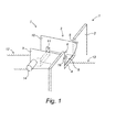
- Fig. 1 shows a perspective view of a flow weir 1 according to the present invention.
- the flow weir 1 comprises a weir wall 2 with a flow passage 3 that is defined by an overflow edge 4 and side edges 5, 6.
- the flow weir 1 further comprises a flow weir 7 that substantially consists of a sealing plate 8 that is connected fixedly to the weir wall 2.
- the sealing plate 8 has a width that is slightly smaller than the width of the passage 3.
- two cheek plates 9, 10 have been provided.
- Said cheek plates 9, 10 are interconnected by means of an overflow edge 11.
- the cheek plates 9, 10 and the overflow edge 11 are able to rotate about a hinge 17 (as shown in Fig.
- a floating body 15 (schematically shown in fig. 2A, 2B , 3A, 3B , 4A and 4B ) has been connected to cheek plate 10.
- Floating bodies 14, 15 have preferably been provided with a water inlet and exit so as to be able to enter ballast into the floating body and to remove it therefrom, respectively.
- the carrying capacity may be adapted, such that the overflow edge's 11 position with respect to the upstream water body's water level 12 may be adapted and, as a consequence, the flow that is passed by said flow weir.
- the fixed part of the flow weir also with reference to all remaining figures, consists of a frame 27 and a sealing plate 8.
- Frame 27 comprises two side posts, a bottom sill, a middle sill and a top sill.
- Said complete frame is constructed on a back plate (for example made of a synthetic material) and is connected with side posts of said frame and connected around a passage 3 of an existing weir wall or a weir wall construction 2.
- Said side posts and bottom sill of said frame are provided with sealing rubber 30 that provides for a sealing between the frame and the outside of the floating part (that is, cheek plates 9, 10 and pivot tube 17).
- the sealing rubber 30 may be incorporated in a container or holder that is connected to said frame parts.
- Said containers or holders may be made of synthetic material.
- Said holders as provided in the side posts also comprise bearing for the pivot tube 17.
- the sealing plate 8 is connected. Same is provided with a sealing rubber 23 surrounding said complete sealing plate (at four sides thereof), providing a sealing between said sealing plate 8 and the cheek plates 9, 10 and the pivot tube 17 that are directed towards the sealing plate. At its bottom side, the sealing plate 8 is provided with struts 19, preventing bending of said flow plate (i.e., said sealing plate) by means of water pressure.
- the flow weir is, at its upstream side, connected with said floating bodies, opposing the flow direction of the water.
- Construction is preferably obtained by a weir wall construction 2 made of wood, concrete or steel comprising a recess 4, 5 and 6, the floating part of the weir, which protrudes behind said frame, being able to freely move through said recess, further comprising recesses for limitation stop 16.
- the complete construction can be connected with a frame to the weir wall by means of bolts.
- the sealing along the sealing plate 8 can be obtained with usually applied sealings 23 (as shown in Fig. 2A, 2B , 3A, 3B , 4A and 4B ).
- Fig. 1 shows a stop 16 connected to cheek plate 9 and abutting against weir wall 2 when flow weir 7 pivots about hinge 17 (see Fig. 2A ), as flow weir 7 moves along with a descending water level 12.
- the cheek plate 9 may comprise a stop 18 (not shown in Fig. 1 , shown in Fig. 2A, 2B , 3A, 3B , 4A and 4B ) at the other side of the weir wall 2, abutting against the other side of the weir wall 2 when the flow weir 7 moves along with the ascending water level 12.
- the cheek plate 10 may comprise similar stoppers 16, 18.
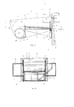
- Fig. 2A shows a schematic side view of flow weir 1 according to Fig. 1 .
- Water flows over overflow edge 11 from upstream water level 12 via sealing plate 8 and passage 3 in weir wall 2 towards downstream water level 13.
- Sealing plate 8 is supported by struts or gusset plates 19 being connected to weir wall. As a result, sealing plate 8 is firmly connected which prevents any deformation and torsion of sealing plate 8.
- cheek plates 9, 10 are interconnected through connection plate 20.
- the shape of connection plate 20 is similar to the radius from pivot shaft 17.
- curved plate 20 or connection plate 20 will abut against sealing plate 8 at every position of flow weir 1.
- the said hinge is on the one hand (directly or indirectly) fixedly connected to weir wall 2 and on the other hand to cheek plates 9, 10.
- cheek plates 9, 10 may be interconnected by means of a connection rod 21.
- Stop 16 may also be constructed by means of a connection rod such that both ends thereof are positioned within recesses in cheek plates 9, 10, wherein both ends function as stoppers 16.
- stoppers 18 may be constructed as a connection rod.
- Floating bodies 14, 15 may be connected to cheek plates 9, 10 respectively.
- the floating bodies may be filled with water as ballast.
- ballast Such aims at adapting the buoyancy of said flow weir 7 to a desired flow rate.
- a higher ballast ensures that the flow weir 7 will be positioned deeper in the upstream water body, and as a consequence the overflow edge 11 will be deeper in the water level 11 and a higher flow rate will be passed through.
- Both floating bodies 14, 15 can be interconnected hydraulically, in the sense of communicating vessels, by means of a conduit 22.
- Fig. 3B shows a partial front view of the embodiment according to Fig. 3A . This embodiment differs from the embodiment according to Fig.
- Floating part of the embodiment in accordance with Fig. 2A, 2B , 3A, 3B , and 4A, 4B consists of two cheek plates 9, 10, a stabilizing floating body 28, two ballast floating bodies 14, 15, a weir plate 24, a curved plate 20, a pivot shaft 17, three spacers 16, 18, 21 and two compensators 29. Furthermore, as shown in Fig. 2B , 3B and 4B three passages 31, 32, 33 are provided in floating bodies 9, 10. Passages 32, 33 serve as vents, whereas passage 31 serves as passage for filling and/or removing ballast.
- passages 32, 33 When filling ballast, for example water, through passage 31, passages 32, 33 will be opened for removing air from floating bodies 28, 14, 15. Passages 31, 32, 33 can be closed after filling ballast has been ended.
- at least one of the passages 32, 33 may be connected to an air compressor of the like. The air filled into the floating bodies will displace ballast through said duct to passage 31.
- a single compressor can be connected to one of said passages 32, 33.
- a pump may be connected to said passage 31 whereas passages 32, 33 serve as vents.
- the stabilizing floating body 28, curved plate 20, pivot tube 17, three spacers and an optional weir plate 24 are provided.
- two controllable ballast floating bodies 14, 15 with passages 31, 32, 33 have been provided.
- Ballast floating bodies 14, 15 are interconnected through stabilizing floating body 28 and commonly provide a compartment.
- the flow weir comprises a weir plate 24 that is positioned between the overflow edge 11 and opening 3.
- Weir plate 24 is sealingly connected to cheek plates 9, 10 all around, and also to curved plate 20 and hinge 17.
- Sealing plate 8 is sealingly beared against curved plate 20 all around, and also to cheek plates 9, 10 and hinge 17.
- a passage 25 has been provided near hinge 17 for accommodating pressure differences between space 26 and the environment.
- Stop 18 abuts against a frame 27, connected to weir wall. According to a further embodiment, stop 18 may abut against weir wall 2.
- Fig. 3A shows an overflow edge 11 protruding from a floating body 27 positioned between cheek plates 9, 10.
- Floating body 27 may be left out, depending on the required buoyancy the floating bodies 14, 15 can provide.
- overflow edge 11 as shown in Fig. 3A may be left out.
- the end of weir plate 24 may serve as overflow edge.
- the embodiment as shown in Fig. 3A and 3B may be adapted, for example by extending weir plate 24 from hinge 17 towards curved plate 20, instead of towards a further position as shown in the present embodiment.
- Fig. 4A shows a side view of an embodiment according to Fig. 3A wherein flow weir takes a position een positie due to a lower upstream water level than was the case in Fig. 3A .
- Weir plate 24 is supported on sealing plate 8.
- stop 16 is supported against frame 27 that is connected to the weir wall.
- stop 16 could be supported against weir wall 2.
- Fig. 4B analogously shows the embodiment according to Fig. 3B .
- the weir's floating part moves along an ascending radius about a pivot point. This movement will be limited by a most forward spacer 18 which protrudes at both sides to such extend through said cheek plates that it also functions as a restrictor.
- ballast is filled into control ballast floating bodies 14, 15, such that a desired overflow height (and a corresponding flow rate) is obtained. Due to the fact that an equilibrium is reached, the weir will follow the upstream water level 12 and provide a constant flow rate within the control area limited by spacers 16, 18 that also serve as restrictors of said control area.
- Stabilizing floating body 28 ensures a stable floating of the weir and ensures that it substantially will not exhibit any bobbing due to billowing.
- the weir's response time depends on the force required to overcome the friction of sealing rubbers 23, 30. Said friction is minimized by providing said rubbers with a special coating and/or applying a tread with a low coefficient of friction.
- Providing the floating bodies with ballast may be obtained manually by opening passage or fill opening 32 and vent vap 33 on ballast floating body and filling water through fill opening 32 in ballast floating body 15 (by means of a watering can, a bucker or a submersible pump).
- fill opening 32 and drain opening 31 are opened and air pressure is applied on the water in the floating bodies through the fill opening 32, a compressor may be used as well as a mouth piece connected to said fill opening and said compressor, with the consequence that the water will be drained from the ballast floating body through drain conduit and drain opening 31.
- floating bodies are deaerated and the openings are closed.
- the ballast's torque will be different in every different position of the ballast floating body, and as a consequence a (minimum) deviation from the flow rate will be obtained.
- two compensators 29 may be used, probably comprising simple weights.
- the invention provides the advantage that a simple flow weir is obtained that can be connected to an existing weir wall in a simple way.
- a fixed part comprising frame parts 27, sealing plate 8 and struts 19 can be connected to the weir wall around the passage in the weir wall.
- the moving part can be positioned, said moving part comprising cheek plates 9, 10, overflow edge 11 and floating bodies 14, 15, 28.
- the hinge may be connected to the fixed frame.
- the complete construction, that is fixed part and moving part may be constructed as a prefab element and be connected as such to the weir wall. Because the position of the overflow edge is determined by the floating bodies alone, the overflow edge will always be positioned at a fixed position with respect to the upstream water level.
- a minimum and maximum position of said overflow edge may be obtained by providing stoppers on said cheek plates, which abut against the weir wall's side edges or against frame parts and as a result will limit the maximum deflection of the weir's moving part.
- the sealing plate 8 provides the advantage that there is no water below the weir plate 24. As a matter of fact, a water level below the weir plate 24 would provide a lifting force on the weir plate and as a consequence the overflow edge's position with respect to the upstream water level would not be constant upon varying upstream water levels.
- the ballast floating bodies 14, 15 are provided at both sides of the cheek plates, such that the water flow is not hindered. It is also preferred, especially when applying barrel shaped floating bodies, that the centre point of said floating bodies is positioned near the upstream water level, which imposes a minimum influence on the floating body's torque that is exerted when the weir rotates along pivot shaft.
- the stabilizing floating body 28 ensures that billowing has little influence on the position of the flow weir in the water.
- plate 24 may comprise protruding baffles.
- Said baffles may be positioned perpendicularly from said plate 24.
- Said baffles may preferably be positioned parallel to said pivot shaft and/or the overflow edge.
- Plate 24 may function as a fishway.
- the baffles may comprise synthetic material, metal, or any other material that can suitably be used for the said purpose.
- the overflow edge may have a same height with respect to the plate 24, as the baffles.
- the baffles' height may increase or even decrease from the overflow edge towards the pivot shaft.
- the invention also relates to every combination of features that have been described independently from each other.
Landscapes
- Engineering & Computer Science (AREA)
- General Engineering & Computer Science (AREA)
- Structural Engineering (AREA)
- Mechanical Engineering (AREA)
- Civil Engineering (AREA)
- Life Sciences & Earth Sciences (AREA)
- Marine Sciences & Fisheries (AREA)
- Barrages (AREA)
Applications Claiming Priority (1)
| Application Number | Priority Date | Filing Date | Title |
|---|---|---|---|
| NL2006999A NL2006999C2 (nl) | 2011-06-27 | 2011-06-27 | Debietstuw. |
Publications (2)
| Publication Number | Publication Date |
|---|---|
| EP2557231A2 true EP2557231A2 (de) | 2013-02-13 |
| EP2557231A3 EP2557231A3 (de) | 2013-04-10 |
Family
ID=46397043
Family Applications (1)
| Application Number | Title | Priority Date | Filing Date |
|---|---|---|---|
| EP12173695.3A Withdrawn EP2557231A3 (de) | 2011-06-27 | 2012-06-26 | Wehranlage |
Country Status (2)
| Country | Link |
|---|---|
| EP (1) | EP2557231A3 (de) |
| NL (1) | NL2006999C2 (de) |
Cited By (3)
| Publication number | Priority date | Publication date | Assignee | Title |
|---|---|---|---|---|
| FR3003582A1 (fr) * | 2013-03-21 | 2014-09-26 | Christian Jacquemin | Passe a poissons flottante. |
| CN110894715A (zh) * | 2019-11-21 | 2020-03-20 | 中国电建集团华东勘测设计研究院有限公司 | 一种装配式鱼道伸缩缝的止水结构及其施工方法 |
| DE112022000155B4 (de) | 2021-03-29 | 2024-10-31 | China Three Gorges Corporation | Pufferfischkanal, der mit reduziertem Schaden für Hochwassernotentlastungen geeignet ist, und Pufferverfahren |
Citations (1)
| Publication number | Priority date | Publication date | Assignee | Title |
|---|---|---|---|---|
| US5139364A (en) | 1989-11-06 | 1992-08-18 | Nagasaki-Ken | Automatic swing fishway apparatus |
Family Cites Families (2)
| Publication number | Priority date | Publication date | Assignee | Title |
|---|---|---|---|---|
| GB2299920A (en) * | 1995-04-20 | 1996-10-23 | Water Power Dev Ltd | Floating fish pass |
| GB9810192D0 (en) * | 1998-05-14 | 1998-07-08 | Timms Cyril A | Self-regulating weirs and fishways |
-
2011
- 2011-06-27 NL NL2006999A patent/NL2006999C2/nl not_active IP Right Cessation
-
2012
- 2012-06-26 EP EP12173695.3A patent/EP2557231A3/de not_active Withdrawn
Patent Citations (1)
| Publication number | Priority date | Publication date | Assignee | Title |
|---|---|---|---|---|
| US5139364A (en) | 1989-11-06 | 1992-08-18 | Nagasaki-Ken | Automatic swing fishway apparatus |
Cited By (3)
| Publication number | Priority date | Publication date | Assignee | Title |
|---|---|---|---|---|
| FR3003582A1 (fr) * | 2013-03-21 | 2014-09-26 | Christian Jacquemin | Passe a poissons flottante. |
| CN110894715A (zh) * | 2019-11-21 | 2020-03-20 | 中国电建集团华东勘测设计研究院有限公司 | 一种装配式鱼道伸缩缝的止水结构及其施工方法 |
| DE112022000155B4 (de) | 2021-03-29 | 2024-10-31 | China Three Gorges Corporation | Pufferfischkanal, der mit reduziertem Schaden für Hochwassernotentlastungen geeignet ist, und Pufferverfahren |
Also Published As
| Publication number | Publication date |
|---|---|
| NL2006999C2 (nl) | 2013-01-02 |
| EP2557231A3 (de) | 2013-04-10 |
Similar Documents
| Publication | Publication Date | Title |
|---|---|---|
| CA2045139C (en) | Automatic swing fishway apparatus | |
| EP2557231A2 (de) | Wehranlage | |
| WO2005012660A8 (en) | Liquid control structure | |
| US4877352A (en) | Method and apparatus for control of an upstream water level | |
| KR20150134854A (ko) | 수문의 수평유지장치를 구비한 유압실린더 개폐 방식의 수문장치 | |
| CN105256770B (zh) | 变配重可控水力自动定轴翻板闸门 | |
| US4456119A (en) | Device for elevating a liquid | |
| CN209100088U (zh) | 一种隧道施工用过断层破碎带排水装置 | |
| CN1079467C (zh) | 水力浮动式转矩平衡重升船机 | |
| US11479943B2 (en) | Buoyant mechanical liquid level control | |
| US3665714A (en) | Canal check gate | |
| RU2609952C1 (ru) | Вакуумная дренажная система | |
| JP2935699B1 (ja) | 浮力利用の自動越流堰 | |
| EP3339648B1 (de) | Flüssigkeitspumpe mit einer luftansaugpumpe und, zwischen den zwei pumpen, einem durch schwimmer betätigten ventil | |
| CN214939914U (zh) | 射流式气浮门 | |
| SU918937A1 (ru) | Регул тор уровн верхнего бьефа | |
| KR102132956B1 (ko) | 부력식 스윙도교 | |
| CN215886389U (zh) | 自动走水闸 | |
| US3665715A (en) | Canal check gate apparatus | |
| CN205100174U (zh) | 变配重可控水力自动定轴翻板闸门 | |
| WO2006058937A1 (es) | Dispositivo de regulación de la descarga para descargadores de cisternas | |
| CN203821336U (zh) | 扇形可调卧式闸门 | |
| CN217808730U (zh) | 一种虾油桶装分装装置 | |
| JP2582620B2 (ja) | 自動操作装置を備えた上流水位調節ゲート | |
| CN111994219B (zh) | 一种基于水利施工的漂浮式可调浮力的施工平台 |
Legal Events
| Date | Code | Title | Description |
|---|---|---|---|
| PUAI | Public reference made under article 153(3) epc to a published international application that has entered the european phase |
Free format text: ORIGINAL CODE: 0009012 |
|
| AK | Designated contracting states |
Kind code of ref document: A2 Designated state(s): AL AT BE BG CH CY CZ DE DK EE ES FI FR GB GR HR HU IE IS IT LI LT LU LV MC MK MT NL NO PL PT RO RS SE SI SK SM TR |
|
| AX | Request for extension of the european patent |
Extension state: BA ME |
|
| PUAL | Search report despatched |
Free format text: ORIGINAL CODE: 0009013 |
|
| AK | Designated contracting states |
Kind code of ref document: A3 Designated state(s): AL AT BE BG CH CY CZ DE DK EE ES FI FR GB GR HR HU IE IS IT LI LT LU LV MC MK MT NL NO PL PT RO RS SE SI SK SM TR |
|
| AX | Request for extension of the european patent |
Extension state: BA ME |
|
| RIC1 | Information provided on ipc code assigned before grant |
Ipc: E02B 7/40 20060101ALI20130305BHEP Ipc: E02B 8/08 20060101ALI20130305BHEP Ipc: E02B 7/20 20060101AFI20130305BHEP |
|
| STAA | Information on the status of an ep patent application or granted ep patent |
Free format text: STATUS: THE APPLICATION IS DEEMED TO BE WITHDRAWN |
|
| 18D | Application deemed to be withdrawn |
Effective date: 20131011 |