EP2557251A2 - Elément de revêtement - Google Patents
Elément de revêtement Download PDFInfo
- Publication number
- EP2557251A2 EP2557251A2 EP12179770A EP12179770A EP2557251A2 EP 2557251 A2 EP2557251 A2 EP 2557251A2 EP 12179770 A EP12179770 A EP 12179770A EP 12179770 A EP12179770 A EP 12179770A EP 2557251 A2 EP2557251 A2 EP 2557251A2
- Authority
- EP
- European Patent Office
- Prior art keywords
- plates
- line
- cladding element
- lines
- element according
- Prior art date
- Legal status (The legal status is an assumption and is not a legal conclusion. Google has not performed a legal analysis and makes no representation as to the accuracy of the status listed.)
- Withdrawn
Links
Images






Classifications
-
- E—FIXED CONSTRUCTIONS
- E04—BUILDING
- E04F—FINISHING WORK ON BUILDINGS, e.g. STAIRS, FLOORS
- E04F13/00—Coverings or linings, e.g. for walls or ceilings
- E04F13/07—Coverings or linings, e.g. for walls or ceilings composed of covering or lining elements; Sub-structures therefor; Fastening means therefor
- E04F13/08—Coverings or linings, e.g. for walls or ceilings composed of covering or lining elements; Sub-structures therefor; Fastening means therefor composed of a plurality of similar covering or lining elements
- E04F13/0871—Coverings or linings, e.g. for walls or ceilings composed of covering or lining elements; Sub-structures therefor; Fastening means therefor composed of a plurality of similar covering or lining elements having an ornamental or specially shaped visible surface
-
- E—FIXED CONSTRUCTIONS
- E04—BUILDING
- E04F—FINISHING WORK ON BUILDINGS, e.g. STAIRS, FLOORS
- E04F13/00—Coverings or linings, e.g. for walls or ceilings
- E04F13/07—Coverings or linings, e.g. for walls or ceilings composed of covering or lining elements; Sub-structures therefor; Fastening means therefor
- E04F13/08—Coverings or linings, e.g. for walls or ceilings composed of covering or lining elements; Sub-structures therefor; Fastening means therefor composed of a plurality of similar covering or lining elements
- E04F13/12—Coverings or linings, e.g. for walls or ceilings composed of covering or lining elements; Sub-structures therefor; Fastening means therefor composed of a plurality of similar covering or lining elements of metal or with an outer layer of metal or enameled metal
Definitions
- the invention relates to a cladding element composed of individual plates.
- the butt joint When panels are assembled into a larger area, the butt joint is visible as a dividing line between the panels. If the panels are provided with a surface structure, the butt joint between the individual panels may interfere with the pattern imprinted or printed on the panels or the structure of the surface.
- the joint between adjacent plates is designed so that the course of the dividing line forms an element of the structure of the surface of the plates, so that when the plates are assembled to a larger area, the visual impression of a uniform, seamless surface is formed ,
- the edges of the panels are designed according to the line structure, so that the joint line between two adjoining panels forms an element of the existing line structure.
- the surfaces may be provided with a structure by means of which the dividing lines between the plates appear as an element of the structure.
- a line structure can be printed on the plates, applied by a foil or applied by etching if the plates are made of metal.
- the invention thus relates to a cladding element, which is composed of a plurality of individual plates, wherein the individual plates have on their surface a structure containing a line-shaped element, and wherein the edges of the plates a the have line-shaped element corresponding shape, so that the separation or impact line between adjacent plates forms an element of the line structure on the plate surface.
- Such a cladding element can be used in many ways, for example, for a visually seamless ceiling, wherein the individual plates may be made of metal.
- the individual plates are attached to a support structure that they can be dismantled so that the space behind the suspended ceiling is accessible for assembly or maintenance work.
- Fig. 1 shows a section of a large-scale, plate-shaped cladding element 1, which in this embodiment has a wavy line structure 2 on the visible side and is composed of individual, adjacent plates 3, 3 '.
- This wavy line structure 2 on the individual plates 3 and 3 ' may be formed by embossing on the plate surface or by printing on a flat surface.
- the butt joint 3a between the adjacent plates 3 and 3 ' is wave-shaped in the same way as the line structure 2, so that the wave-shaped butt joint 3a forms an element of the surface structure 2.
- This embodiment is particularly suitable for structures on the Plate surface suitable having a deviating from a straight line line structure.
- the structure 2 is preferably at least partially embossed or deformation of the surface of the individual plates 3, 3 ', so that the wave-shaped line structure 2 in Fig. 1 in the form of ribs or grooves on the plates 3, 3 'is formed.
- Fig. 2 schematically shows cross sections through the butt joint 3a between two adjacent plates 3 and 3 ', wherein the line structure on the visible side in Fig. 2a is formed by a cross-sectionally U-shaped recess 4.
- the edge of the plates is each provided with a shoulder 4a, so that the abutting plates form a U-shaped recess or groove 4 at the joint line 3a as a line structure through the grooves 4 is formed on the remaining surface.
- Fig. 2b shows a V-shaped recess 4 on the plates 3, 3 'to form a line structure 2, wherein at the joint line 3a, the edges of the adjacent plates at 4b are only chamfered to form the V-shaped line structure 4 together.
- Fig. 2c shows an embodiment in which the line structure 2 on the surface of the plates 3, 3 'is formed by elevations in the form of ribs 5.
- the edges of the adjacent plates each have a half rib 5a, so that in adjacent plates 3, 3 'results in a complete rib shape 5, as formed on the remaining surface of the plates.
- the line structure on the surface of the plates can also be formed by a combination of grooves 4 and elevations or ribs 5.
- Fig. 3 shows a polygonal line structure 2, which forms adjacent fields 2a with six straight sides.
- a recess 6 is formed in this embodiment, wherein in each recess 6, a hole 7 is provided, into which a fastening screw 10 can be used.
- the edges 3a of the plates 3, 3 'of which the lining element 1 is composed are formed by the delimiting lines of the hexagons, so that adjacent plates 3, 3' mesh with one another similar to a toothing with the edges.
- the joint line 3a is in this case, for example Fig. 2a formed, wherein the side lines of the hexagons 2a also form a groove 4.
- Such a surface element 1 after Fig. 3 Due to its surface structure, it can be used as a soundproofing cladding element.
- the individual plates 3, 3 ' may be made of sheet metal, which may have a thickness of, for example, 0.3 to 2 mm.
- a support member to which the cladding element 1 and the plates 3 are attached.
- the attachment can be done in various ways, for example, by magnetic technology.
- Fig. 6 shows in section a surface structure of a plate 3, which is formed of adjacent recesses 3.1 and intermediate elevations 3.2.
- a sandwich construction may be provided in which on the back of the plate 3, a flat plate 8 made of metal in good heat conductive contact is applied, so that on the back of the plate 8 a heating - or cooling coil can be attached and the smooth surface of the flat plate 8 ensures good heat transfer to the structured plate 3.
- a different perforation For example, around the in Fig. 3 reproduced holes 7 may be formed a smaller perforation in order to better absorb a certain frequency range of the sound can.
- Various types of perforations of the cladding elements or plates 3 can be provided, wherein perforations of different sizes can also be provided.
- Fig. 4 and 5 show modified embodiments of the surface structuring.
- Fig. 4a shows schematically the view of a line structure 2 with parallel and intersecting lines bounding square fields.
- rectangular or square recesses 7 ' are formed alternately in diagonal rows.
- the provided with a recess 7 'fields can be raised and have pyramidally inclined surface sections, while the intermediate fields can be designed flat.
- the butt joint runs along a straight line along the edges of the juxtaposed rectangles, whereby it is also possible to form the butt joint in the manner of a toothing between adjacent plates, as shown at the left edge in FIG Fig. 4a at 3a is interpreted.
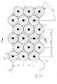
- Fig. 5a shows the view of a surface structure with round fields, each having a hole 7 in the middle.
- Fig. 5b shows a sectional view of the plate after Fig. 5a ,
- the individual round fields are formed recessed by embossing similar to the embodiment according to Fig. 3
- Fig. 5c shows a bead 9, which encloses the individual round fields and the in Fig. 5a reproduced line structure 2 forms.
- the edges of the plates 3, 3 ' are provided with a half bead 9, so that abutting plate edges 3a a whole bead 9 after Fig. 5c form.
- the described surface structures essentially show a uniform pattern. However, it is also possible to design the line structure in such a way that unequal distances of the individual line elements result. Also, the grooves resulting in the line structure or ribs of different sizes. According to a further embodiment, it is possible to form the line structure not continuously, but with interruptions, wherein the joint line 3a forms an element of such a structure provided with interruptions.
- the surface elements can be fixed by gluing on a substrate. If an optically seamless ceiling structure is provided, the individual plates are preferably removably fastened by screws, clip elements or other fastening elements to a support structure.
- the holes 7 in Fig. 3 and 5 be used for inserting screws or fasteners that are screwed into a non-illustrated holding element, such as a mounting rail.
- the heads of the screws 10 or clip elements can, as Fig. 7 shows, with a central recess 10a be designed so that they do not affect the structure of the surface of the surface element and are barely visible.
- Fig. 7 shows in a plan view and in a sectional view of a screw with a cup-shaped head part 10b, in the middle of the recess 10a is formed corresponding to a hole 7 in the other recesses.
- this recess 10a is designed as a hexagon or the like, so that a tool can be used for twisting.
- the radius of curvature of the cup-shaped head portion 10b is to the radius of curvature of the recess 6 or 3.2 in the embodiment according to Fig. 3 or 6 customized.
- the edges can be designed or provided with an additional element that the adjacent plates are held in a plane.
- an overlap with the adjacent plate in the joint area can be provided on one side of the plates.
- a skirt can be provided, which is adapted to one side of the line structure of the surface corresponding to the edge of a single plate 3 and on the opposite side has a straight boundary line for connection to a wall or the like.
- a line pattern is printed on the smooth plates 3, 3 'or applied by a film, through which the line of intersection between the individual plates as an element by printing or by a foil applied structure appears.
- the structure can also be etched on the surface of the plates.
- the printed structure can also be formed in different colors.
- the line resulting from the dividing line between two plates may be colored red and the line structure printed on the plates may be rendered in red or in other colors.
- a line structure can be printed, which makes the dividing lines 3a between the perforated plates appear as an element of the printed line structure.
- the printed line structure can also give an uneven pattern and it does not necessarily have to be aligned with the existing dividing lines 3a between the plates.
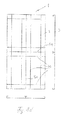
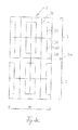
- Fig. 8 shows in a view of a cladding element 1 of composite panels 3 embodiments of a printed, embossed or etched structure for laminating the dividing lines 3a, wherein for clarity a side view of the cladding element 1 is reproduced, which reveals the size of the plates 3, with angled edge portions abut each other.
- Fig. 8a shows a surface element 1, which is composed of four rectangular plates 3, so that there are bump lines or separation lines 3a.
- intersecting lines 30 are printed on each plate, applied by a foil, or formed by etching or by embossing, so that through this structure 30th of intersecting lines, the dividing lines 3a between adjacent plates 3 give an element of the overall structure on the surface element 1.
- the applied structure is such that one of the intersecting lines 30 of the structure is shortened at 30 '.
- the dividing line 3a appear as part of the structure.
- Fig. 8c shows a modified embodiment of the structure according to Fig. 8b , in which Fig. 8c a combination of structures in Fig. 8a and 8b reproduces.
- Fig. 8d shows a structure applied to the plates 3 structure of lines 40 which is parallel to the edges and the dividing lines 3a between them appear as a structural element.
- Fig. 8e shows a structure in which the angled lines 50 in conjunction with the intersecting lines 30 of FIG Fig. 8a are applied, so that an overall structure of the cladding element 1 of intersecting lines 3a, 30 with interposed rectangles from the lines 50 results. Also in this embodiment, the dividing lines 3a appear between the four plates 3 as an element of the structure of the lining element 1.
- Fig. 8f shows a modification of the structure Fig.
- Fig. 8g shows a structure based on the structure Fig. 8a , wherein obliquely extending lines 60 are provided in connection with the lines crossing in the middle of a rectangular plate 30, and at the intersection of the oblique lines 60 there is in each case a line of the structure running parallel to the edges of the plate. Characterized in that the applied structure by the larger number of lines 30 and 60 acts more dense, the dividing lines 3a between the four rectangular plates are no longer recognizable as dividing lines.
- Fig. 9 a section of a structure on a surface element 1, which is composed of diamond-shaped plates 3, so that a rhombic structure of the dividing lines 3a results.
- a line 70 can be applied between opposite corner points of the plates 3, which does not let the dividing lines 3a optically emerge.
- connecting lines are applied to make the structure of the cladding element 1 denser and thereby make the parting lines 3a appear as an element of the structure.
- the described design can be provided not only in flat plates, but also in curved plates, which form a curved cladding element in the assembled state.
Landscapes
- Engineering & Computer Science (AREA)
- Architecture (AREA)
- Civil Engineering (AREA)
- Structural Engineering (AREA)
- Finishing Walls (AREA)
- Linear Motors (AREA)
Applications Claiming Priority (1)
| Application Number | Priority Date | Filing Date | Title |
|---|---|---|---|
| DE201110109924 DE102011109924A1 (de) | 2011-08-10 | 2011-08-10 | Verkleidungselement |
Publications (2)
| Publication Number | Publication Date |
|---|---|
| EP2557251A2 true EP2557251A2 (fr) | 2013-02-13 |
| EP2557251A3 EP2557251A3 (fr) | 2014-03-19 |
Family
ID=46880558
Family Applications (1)
| Application Number | Title | Priority Date | Filing Date |
|---|---|---|---|
| EP12179770.8A Withdrawn EP2557251A3 (fr) | 2011-08-10 | 2012-08-09 | Elément de revêtement |
Country Status (2)
| Country | Link |
|---|---|
| EP (1) | EP2557251A3 (fr) |
| DE (1) | DE102011109924A1 (fr) |
Cited By (1)
| Publication number | Priority date | Publication date | Assignee | Title |
|---|---|---|---|---|
| WO2022148532A1 (fr) * | 2021-01-05 | 2022-07-14 | Durlum Group Gmbh | Élément de placage, placage, système de guidage de personnes et utilisation d'un élément de placage |
Family Cites Families (5)
| Publication number | Priority date | Publication date | Assignee | Title |
|---|---|---|---|---|
| FR1150222A (fr) * | 1955-06-16 | 1958-01-09 | Servais Werke A G | Plaque, carreau ou article analogue |
| DE1659601A1 (de) * | 1967-11-14 | 1971-01-28 | Jakob Braun | Verlegeplatte |
| US6667109B1 (en) * | 2002-09-23 | 2003-12-23 | Style Solutions, Incorporated | Two-piece decorative medallion |
| AT505298B1 (de) * | 2007-04-19 | 2008-12-15 | Karl Ing Kleebinder | Plattenförmiges verkleidungselement für eine mauer und mauerverkleidung |
| AU2011100232A4 (en) * | 2011-03-01 | 2011-03-31 | Nichiha Corporation | Construction structure of wall surface |
-
2011
- 2011-08-10 DE DE201110109924 patent/DE102011109924A1/de not_active Withdrawn
-
2012
- 2012-08-09 EP EP12179770.8A patent/EP2557251A3/fr not_active Withdrawn
Non-Patent Citations (1)
| Title |
|---|
| None |
Cited By (1)
| Publication number | Priority date | Publication date | Assignee | Title |
|---|---|---|---|---|
| WO2022148532A1 (fr) * | 2021-01-05 | 2022-07-14 | Durlum Group Gmbh | Élément de placage, placage, système de guidage de personnes et utilisation d'un élément de placage |
Also Published As
| Publication number | Publication date |
|---|---|
| EP2557251A3 (fr) | 2014-03-19 |
| DE102011109924A1 (de) | 2013-02-14 |
Similar Documents
| Publication | Publication Date | Title |
|---|---|---|
| EP0504629B1 (fr) | Elément absorbant le son en forme de panneau, et dispositif absorbant le son | |
| EP1631728B1 (fr) | Rail profile et procede de realisation d'un rail profile | |
| DE10259307A1 (de) | Flächiges Metallelement und Profilelement | |
| EP2557251A2 (fr) | Elément de revêtement | |
| DE202007012261U1 (de) | Wärmetauscher | |
| DE2110318C3 (de) | Mosaik-Schaltbild | |
| DE19640128A1 (de) | Bodenbelag-Element | |
| WO2004072405A1 (fr) | Sol | |
| EP2568466B1 (fr) | Dispositif d'éclairage | |
| DE202008016451U1 (de) | Schallschutzwandelement | |
| EP2055455A1 (fr) | Procédé de fabrication de lamelles pour planchers | |
| DE10147645A1 (de) | Schallabschirmelement und Verfahren zur Herstellung | |
| AT401950B (de) | Aus nebeneinanderliegend angeordneten blechbahnen bestehende dacheindeckung | |
| DE2203909C2 (de) | Bauwerksverkleidung | |
| DE3029664C2 (de) | Unterdecke | |
| DE202005012459U1 (de) | Deckenelement für abgehängte Decken | |
| DE20112577U1 (de) | Lösbarer und wiederverwendungsfähiger Abstandshalter für das Verlegen von plattenförmigen Wand- und Bodenbekleidungselementen | |
| DE19831094C2 (de) | Deckenkonstruktion für eine Profilrasterdecke | |
| DE102023120313A1 (de) | Verkleidungsplatte | |
| DE102021208733A1 (de) | Staubschutzplatte zur Reduzierung von Bremsgeräuschen und Bremssystem mit einem Staubschutzblech | |
| DE102023120314A1 (de) | Verkleidungsplatte | |
| DE29619923U1 (de) | Wand- und Bodenbelag | |
| DE202015004914U1 (de) | Erdankerplatte | |
| DE202004013301U1 (de) | Fußmatte | |
| EP3911800A1 (fr) | Pavé présentant une structuration périphérique et pavage posé à l'aide de ce dernier |
Legal Events
| Date | Code | Title | Description |
|---|---|---|---|
| PUAI | Public reference made under article 153(3) epc to a published international application that has entered the european phase |
Free format text: ORIGINAL CODE: 0009012 |
|
| AK | Designated contracting states |
Kind code of ref document: A2 Designated state(s): AL AT BE BG CH CY CZ DE DK EE ES FI FR GB GR HR HU IE IS IT LI LT LU LV MC MK MT NL NO PL PT RO RS SE SI SK SM TR |
|
| AX | Request for extension of the european patent |
Extension state: BA ME |
|
| RIN1 | Information on inventor provided before grant (corrected) |
Inventor name: KIERMAIER, ALOIS |
|
| PUAL | Search report despatched |
Free format text: ORIGINAL CODE: 0009013 |
|
| AK | Designated contracting states |
Kind code of ref document: A3 Designated state(s): AL AT BE BG CH CY CZ DE DK EE ES FI FR GB GR HR HU IE IS IT LI LT LU LV MC MK MT NL NO PL PT RO RS SE SI SK SM TR |
|
| AX | Request for extension of the european patent |
Extension state: BA ME |
|
| RIC1 | Information provided on ipc code assigned before grant |
Ipc: E04F 13/08 20060101AFI20140211BHEP Ipc: E04F 13/12 20060101ALI20140211BHEP |
|
| STAA | Information on the status of an ep patent application or granted ep patent |
Free format text: STATUS: THE APPLICATION IS DEEMED TO BE WITHDRAWN |
|
| 18D | Application deemed to be withdrawn |
Effective date: 20140920 |