EP2557328A2 - Dispositif de roulement de libération dýembrayage - Google Patents
Dispositif de roulement de libération dýembrayage Download PDFInfo
- Publication number
- EP2557328A2 EP2557328A2 EP12177413A EP12177413A EP2557328A2 EP 2557328 A2 EP2557328 A2 EP 2557328A2 EP 12177413 A EP12177413 A EP 12177413A EP 12177413 A EP12177413 A EP 12177413A EP 2557328 A2 EP2557328 A2 EP 2557328A2
- Authority
- EP
- European Patent Office
- Prior art keywords
- movable sleeve
- clutch release
- release bearing
- outer periphery
- radially
- Prior art date
- Legal status (The legal status is an assumption and is not a legal conclusion. Google has not performed a legal analysis and makes no representation as to the accuracy of the status listed.)
- Withdrawn
Links
- 230000005540 biological transmission Effects 0.000 description 14
- 230000004323 axial length Effects 0.000 description 12
- 230000008878 coupling Effects 0.000 description 5
- 238000010168 coupling process Methods 0.000 description 5
- 238000005859 coupling reaction Methods 0.000 description 5
- 238000005096 rolling process Methods 0.000 description 4
- 238000001746 injection moulding Methods 0.000 description 3
- 230000002093 peripheral effect Effects 0.000 description 3
- 229920003002 synthetic resin Polymers 0.000 description 3
- 239000000057 synthetic resin Substances 0.000 description 3
- 239000000463 material Substances 0.000 description 2
- 239000002184 metal Substances 0.000 description 2
- 230000000717 retained effect Effects 0.000 description 2
- 230000015572 biosynthetic process Effects 0.000 description 1
- 230000009977 dual effect Effects 0.000 description 1
- 230000000694 effects Effects 0.000 description 1
Images



Classifications
-
- F—MECHANICAL ENGINEERING; LIGHTING; HEATING; WEAPONS; BLASTING
- F16—ENGINEERING ELEMENTS AND UNITS; GENERAL MEASURES FOR PRODUCING AND MAINTAINING EFFECTIVE FUNCTIONING OF MACHINES OR INSTALLATIONS; THERMAL INSULATION IN GENERAL
- F16D—COUPLINGS FOR TRANSMITTING ROTATION; CLUTCHES; BRAKES
- F16D23/00—Details of mechanically-actuated clutches not specific for one distinct type
- F16D23/12—Mechanical clutch-actuating mechanisms arranged outside the clutch as such
- F16D23/14—Clutch-actuating sleeves or bearings; Actuating members directly connected to clutch-actuating sleeves or bearings
-
- F—MECHANICAL ENGINEERING; LIGHTING; HEATING; WEAPONS; BLASTING
- F16—ENGINEERING ELEMENTS AND UNITS; GENERAL MEASURES FOR PRODUCING AND MAINTAINING EFFECTIVE FUNCTIONING OF MACHINES OR INSTALLATIONS; THERMAL INSULATION IN GENERAL
- F16D—COUPLINGS FOR TRANSMITTING ROTATION; CLUTCHES; BRAKES
- F16D23/00—Details of mechanically-actuated clutches not specific for one distinct type
- F16D23/12—Mechanical clutch-actuating mechanisms arranged outside the clutch as such
- F16D23/14—Clutch-actuating sleeves or bearings; Actuating members directly connected to clutch-actuating sleeves or bearings
- F16D23/148—Guide-sleeve receiving the clutch release bearing
-
- F—MECHANICAL ENGINEERING; LIGHTING; HEATING; WEAPONS; BLASTING
- F16—ENGINEERING ELEMENTS AND UNITS; GENERAL MEASURES FOR PRODUCING AND MAINTAINING EFFECTIVE FUNCTIONING OF MACHINES OR INSTALLATIONS; THERMAL INSULATION IN GENERAL
- F16D—COUPLINGS FOR TRANSMITTING ROTATION; CLUTCHES; BRAKES
- F16D21/00—Systems comprising a plurality of actuated clutches
- F16D21/02—Systems comprising a plurality of actuated clutches for interconnecting three or more shafts or other transmission members in different ways
- F16D21/06—Systems comprising a plurality of actuated clutches for interconnecting three or more shafts or other transmission members in different ways at least two driving shafts or two driven shafts being concentric
Definitions
- the invention relates to a clutch release bearing device that is employed in a dual clutch transmission (hereinafter, simply referred to as "DCT").
- DCT dual clutch transmission
- a conventional clutch release bearing device employed in a dry DCT is described in, for example, Japanese Patent Application Publication No. 2010-156402 ( JP 2010-156402 A ).
- the conventional clutch release bearing device employed in a dry DCT includes a first movable sleeve 210, a first clutch release bearing 240, a second movable sleeve 250, and a second clutch release bearing 270.
- the first movable sleeve 210 is arranged on the outer periphery of a retainer 9 so as to be slidable in the axial direction.
- the first clutch release bearing 240 is fitted to a first cover member 230.
- the first cover member 230 is arranged in front of a flange 210a (on the right side of the flange 210a in FIG. 5 ) formed at one end side of the first movable sleeve 210.
- the first clutch release bearing 240 actuates a first diaphragm spring (not shown).
- the second movable sleeve 250 is fitted to the outer periphery of the first movable sleeve 210 so as to be slidable in the axial direction.
- the second clutch release bearing 270 is directly fitted to the front side of the second movable sleeve 250.
- the second movable sleeve 250 is fitted to a second cover member 260.
- the second clutch release bearing 270 actuates a second diaphragm spring (not shown).
- a first sliding portion 245 and a second sliding portion 246 are formed on the outer periphery of the first movable sleeve 210 at portions located behind the flange 210a (on the left side of the flange 210a in FIG. 5 ).
- the first sliding portion 245 slidingly guides the second movable sleeve 250 relative to the first movable sleeve 210 in the axial direction.
- the second sliding portion 246 slidingly guides the second movable sleeve 250 in the axial direction.
- the first clutch release bearing 240 is arranged in front of the flange 210a of the first movable sleeve 210 via the first cover member 230, and the first sliding portion 245 and the second sliding portion 246 for the second movable sleeve 250 are formed behind the flange 210a. Therefore, a length L1' of a portion of the first movable sleeve 210 behind the flange 210a is equal to or slightly longer than the sum of an axial length L2' of the second movable sleeve 250, an axial length L3' of the first sliding portion 245 and an axial length L4' of the second sliding portion 246. Thus, an axial length L' of the clutch release bearing device becomes long.
- An aspect of the invention relates to a clutch release bearing device that includes: a first movable sleeve that is slidably fitted to an outer periphery of a retainer, and that is slid by a first release fork in an axial direction; a first clutch release bearing that is fitted to the first movable sleeve, and that actuates a first diaphragm spring; a guide cylinder that is fixedly arranged on an outer periphery of the first movable sleeve so as to be movable together with the first movable sleeve; a second movable sleeve that is slidably fitted to an outer periphery of the guide cylinder, and that is slid by a second release fork in the axial direction; and a second clutch release bearing that is fitted to the second movable sleeve, and that actuates a second diaphragm spring.
- An extended cylindrical portion that accommodates the first clutch release bearing is formed at an end portion of the guide cylinder, which faces the first diaphragm spring.
- a first sliding portion and a second sliding portion are formed on the outer periphery of the guide cylinder including the extended cylindrical portion.
- the second sliding portion slidingly guides the second movable sleeve in the axial direction.
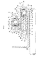
- a clutch release bearing device employed in a dry DCT includes a first movable sleeve 10, a first clutch release bearing 30, a guide cylinder 40, a second movable sleeve 50 and a second clutch release bearing 70.
- the first movable sleeve 10 is arranged between a first release fork 5 and a first diaphragm spring 7.
- the second movable sleeve 50 is arranged between a second release fork 6 and a second diaphragm spring 8.
- the first movable sleeve 10 is formed into a cylindrical shape having a bore diameter slightly larger than the outside diameter of a retainer 9, by subjecting a synthetic resin material to injection molding.
- the first movable sleeve 10 is fitted to the outer periphery of the retainer 9 so as to be slidable in the axial direction.
- spaces 13 are formed at a radially middle portion with a coupling portion 14 left at the center in the axial direction. Formation of the spaces 13 reduces the weight of the first movable sleeve 10, and prevents deformation due to shrinkage after the injection molding.
- annular radially-inner side contact portions 11 are formed near respective axial end portions of the inner periphery of the first movable sleeve 10.
- the radially-inner side contact portions 11 slidably contact the outer periphery of the retainer 9.
- a portion of the inner periphery of the first movable sleeve 10 other than the radially-inner side contact portions 11 is larger in diameter than each of the radially-inner side contact portions 11, and is held so as not to be in contact with the outer periphery of the retainer 9.
- annular radially-outer side contact portions 12 are formed near respective axial end portions of the outer periphery of the first movable sleeve 10.
- the radially-outer side contact portions 12 are press-fitted to and in contact with the inner periphery of the guide cylinder 40 (described in detail below).
- a portion of the outer periphery of the first movable sleeve 10 other than the radially-outer side contact portions 12 is smaller in diameter than each of the radially-outer side contact portions 12, and is held so as not to be in contact with the inner periphery of the guide cylinder 40.
- the retainer 9 has a cylindrical shape, and extends from a transmission case (not shown) of the dry DCT.
- a cylindrical first power transmission shaft 3 is arranged in the cylindrical retainer 9.
- a second power transmission shaft 4 is passed through the center portion of the first power transmission shaft 3.
- the first power transmission shaft 3 is connected to an output shaft side of an engine via a first clutch mechanism (not shown) such that torque is transmittable through the first power transmission shaft 3.
- the second power transmission shaft 4 is connected to the output shaft side of the engine via a second clutch mechanism (not shown) such that torque is transmittable through the second power transmission shaft 4.
- the first clutch release bearing 30 includes an outer ring 31, an inner ring 35 and rolling elements (balls in FIG. 1 ) 32.
- the rolling elements 32 are rollably arranged between these outer ring 31 and inner ring 35, and are retained by a cage 33.
- the first clutch release bearing 30 is fitted to one end portion (end portion closer to the first diaphragm spring 7) of the first movable sleeve 10 via a first cover member 20.
- the first cover member 20 has a fixing cylindrical portion 21, an annular portion 22 and a radially-outer side cylindrical portion 23.
- the fixing cylindrical portion 21 is press-fitted to the large-diameter-side inner periphery, which defines the space 13 at one end side of the first movable sleeve 10.
- the annular portion 22 is formed in an annular shape and extends radially outward from the outer periphery of one end portion of the fixing cylindrical portion 21 along one end face of the first movable sleeve 10.
- the radially-outer side cylindrical portion 23 has a cylindrical shape, and extends from the radially-outer end of the annular portion 22.
- the outside diameter of the radially-outer side cylindrical portion 23 is slightly smaller than the outside diameter of the first movable sleeve 10.
- the outer ring 31 of the first clutch release bearing 30 is press-fitted to the inner periphery of the radially-outer side cylindrical portion 23.
- a pushing portion 36 is formed at one end of the inner ring 35 of the first clutch release bearing 30. The pushing portion 36 pushes a radially-inner side portion of the first diaphragm spring 7.
- the guide cylinder 40 is formed by forming a metal sheet into a cylindrical shape, and is fixedly arranged on the outer periphery of the first movable sleeve 10 over the entire axial length of the first movable sleeve 10 so as to be movable together with the first movable sleeve 10.
- An extended cylindrical portion 42 is formed at one end portion of the guide cylinder 40, which faces the first diaphragm spring 7.
- the extended cylindrical portion 42 accommodates the first clutch release bearing 30 together with the first cover member 20.
- a first link portion 41 is formed at the other end portion of the guide cylinder 40, which faces the first release fork 5.
- the first link portion 41 is coupled to the first release fork 5.
- the first link portion 41 has an annular portion 41a and a coupling portion 41b.
- the annular portion 41a is formed in an annular shape, and extends radially inward from the end portion of the guide cylinder 40, which faces the first release fork 5, so as to be in contact with the end face of the first movable sleeve 10.
- the first link portion 41 is bent such that the coupling portion 41b extends from the radially-inner end of the annular portion 41a so as to be coupled to the first release fork 5. The movement of the first release fork 5 is transmitted to the first movable sleeve 10 via the first link portion 41.
- the second movable sleeve 50 is fitted to the outer periphery of the guide cylinder 40.
- a first sliding portion 45 and a second sliding portion 46 are formed on the outer periphery of the guide cylinder 40 including the extended cylindrical portion 42.
- the first sliding portion 45 slidingly guides the second movable sleeve 50 relative to the first movable sleeve 10 in the axial direction.
- an axial length (cylinder length) L1 of the guide cylinder 40 including the extended cylindrical portion 42 is equal to or slightly longer than the sum of an axial length L2 of the second movable sleeve 50, an axial length L3 of the first sliding portion 45 and an axial length L4 of the second sliding portion 46.
- the second movable sleeve 50 is formed into a cylindrical shape having a bore diameter equal to or slightly larger than the outside diameter of the guide cylinder 40 by subjecting a synthetic resin material to injection molding.
- the second movable sleeve 50 is fitted to the outer periphery of the guide cylinder 40 so as to be slidable in the axial direction.
- a second link portion 55 and a second cover member 60 are fixed to the outer periphery of the second movable sleeve 50, at a position near the axial center of the second movable sleeve 50.
- the second link portion 55 is coupled to the second release fork 6.
- the second clutch release bearing 70 is fitted to the second cover member 60.
- the second link portion 55 has a fixing cylindrical portion 56, an annular portion 57 and a coupling portion 58.
- the fixing cylindrical portion 56 is fixedly embedded in an outer peripheral portion of the second movable sleeve 50.
- the annular portion 57 is formed in an annular shape, and extends radially outward from one end of the fixing cylindrical portion 56.
- the second link 55 is bent such that the coupling portion 58 extends from the radially-outer end of the annular portion 57 so as to be coupled to the second release fork 6. The movement of the second release fork 6 is transmitted to the second movable sleeve 50 via the second link portion 55.
- the second cover member 60 has a fixing cylindrical portion 61, an annular portion 62 and a radially-outer side cylindrical portion 63.
- the fixing cylindrical portion 61 is fixedly embedded in the outer peripheral portion of the second movable sleeve 50 while being fitted to the outer periphery of the fixing cylindrical portion 56 of the second link portion 55.
- the annular portion 62 is formed in an annular shape, and extends radially outward from the outer periphery of one end portion of the fixing cylindrical portion 61 along the annular portion 57 of the second link portion 55.
- the radially-outer side cylindrical portion 63 is formed in a cylindrical shape, and extends from the radially-outer end of the annular portion 62.
- the second clutch release bearing 70 includes an outer ring 71, an inner ring 75 and rolling elements (balls in FIG. 1 ) 72.
- the rolling elements 72 are rollably arranged between the outer ring 71 and the inner ring 75, and are retained by a cage 73.
- the outer ring 71 of the second clutch release bearing 70 is press-fitted to the inner periphery of the radially-outer side cylindrical portion 63 of the second cover member 60.
- a pushing portion 76 is formed at one end of the inner ring 75 of the second clutch release bearing 70. The pushing portion 76 pushes a radially-inner side portion of the second diaphragm spring 8.
- the clutch release bearing device employed in a dry DCT according to the first embodiment is configured as described above. Therefore, as shown in FIG. 2 , when the first movable sleeve 10 together with the first link portion 41 is slid by the first release fork 5 on the outer periphery of the retainer 9 in the axial direction and is placed at an actuating position with the second movable sleeve 50 arranged at a standby position, the radially-inner side portion of the first diaphragm spring 7 is pushed by the pushing portion 36 of the inner ring 35 of the first clutch release bearing 30. Thus, the first clutch mechanism (not shown) is placed in a connected state, and torque is transmitted from the output shaft side of the engine to the first power transmission shaft 3.
- the first clutch release bearing 30 is accommodated in the extended cylindrical portion 42 of the guide cylinder 40 that is fixedly arranged on the outer periphery of the first movable sleeve 10 so as to be movable together with the first movable sleeve 10, and the first sliding portion 45 and the second sliding portion 46 are formed on the outer periphery of the guide cylinder 40 including the extended cylindrical portion 42.
- the axial length L of the clutch release bearing device is reduced by an amount corresponding to the axial length of the first clutch release bearing 30 that is accommodated in the extended cylindrical portion 42 of the guide cylinder 40 (see FIG. 1 ), in comparison with a conventional art, as shown in FIG.
- a first clutch release bearing 240 is arranged in front of a flange 210a formed at one end side of a first movable sleeve 210 and a first sliding portion 245 and a second sliding portion 246 are formed behind the flange 210a.
- the annular radially-inner side contact portions 11 formed in the inner periphery of the first movable sleeve 10 at the positions near the respective axial end portions slidably contact the outer periphery of the retainer 9.
- the portion of the inner periphery of the first movable sleeve 10, other than radially-inner side contact portions 11, is formed so as to be larger in diameter than each radially-inner side contact portion 11. Thus, this portion is held so as not to be in contact with the outer periphery of the retainer 9.
- the first movable sleeve 10 slides over the outer periphery of the retainer 9 in the axial direction, it is possible to suppress tilting of the first movable sleeve 10 with respect to the axial direction of the retainer 9. As a result, the first movable sleeve 10 is smoothly slid over the outer periphery of the retainer 9 in the axial direction.
- the annular radially-outer side contact portions 12 formed in the outer periphery of the first movable sleeve 10 at the positions near the respective axial end portions are press-fitted to and in contact with the inner periphery of the guide cylinder 40.
- the portion of the outer periphery of the first movable sleeve 10, other than the radially-outer side contact portions 12, is formed so as to be smaller in diameter than each radially-outer side contact portion 12.
- this portion is held so as not to be in contact with the inner periphery of the guide cylinder 40. Therefore, when the guide cylinder 40 is fixedly press-fitted to the outer periphery of the first movable sleeve 10, it is possible to suppress tilting of the guide cylinder 40 with respect to the axial direction of the first movable sleeve 10. As a result, the second movable sleeve 50 is smoothly slid over the outer periphery of the guide cylinder 40 in the axial direction.
- the guide cylinder 40 is made of metal, it is possible to reduce the sliding resistance of the second movable sleeve 50 in comparison with the case where the guide cylinder 40 is made of synthetic resin.
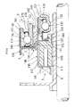
- a clutch release bearing device As shown in FIG. 4 , in the second embodiment, a first clutch release bearing 130 is fitted to a first movable sleeve 110 so as to be movable in the radial direction to provide an aligning function, and a second clutch release bearing 170 is fitted to a second movable sleeve 150 so as to be movable in the radial direction to provided an aligning function. That is, an annular portion 122 of a first cover member 120 is fitted to a support portion 115 formed at one end portion of the first movable sleeve 110 via a first aligning spring 180 so as to be movable in the radial direction.
- the first aligning spring 180 is formed of a coned disc spring.
- an outer ring 131 of the first clutch release bearing 130 is press-fitted to a radially-outer side cylindrical portion 123 of the first cover member 120.
- an outer ring 171 of the second clutch release bearing 170 is fitted to a radially-outer side cylindrical portion 163 of a second cover member 160 that is fixed to the outer periphery of the second movable sleeve 150 so as to be movable in the radial direction.
- a spring receiving portion 165 that is formed in an annular shape and that extends radially inward is formed at the distal end of the radially-outer side cylindrical portion 163.
- a second aligning spring 181 formed of a wave spring washer is interposed between the end face of the outer ring 171 and the spring receiving portion 165.
- annular radially-inner side contact portions 111 are formed in the inner periphery of the first movable sleeve 110 at the positions near the respective axial end portions.
- the radially-inner side contact portions 111 slidably contact the outer periphery of the retainer 9.
- a portion of the inner periphery of the first movable sleeve 110, other than the radially-inner side contact portions 111, is larger in diameter than each radially-inner side contact portion 111, and is held so as not to be in contact with the outer periphery of the retainer 9.
- annular radially-outer side contact portions 112 are formed in the outer periphery of the first movable sleeve 110 at the positions near the respective axial end portions.
- the radially-outer side contact portions 112 are press-fitted to the inner periphery of the guide cylinder 140.
- a portion of the outer periphery of the first movable sleeve 110, other than the radially-outer side contact portions 112, is smaller in diameter than each radially-outer side contact portion 112, and is held so as not to be in contact with the inner periphery of the guide cylinder 140.
- an extended cylindrical portion 142 is formed at one end portion of the guide cylinder 140, which faces the first diaphragm spring 7.
- the extended cylindrical portion 142 accommodates the first clutch release bearing 130 together with the first cover member 120.
- a first link portion 141 is formed at the other end portion of the guide cylinder 140, which faces the first release fork 5.
- the first link portion 141 is coupled to the first release fork 5.
- a first sliding portion 145 and a second sliding portion 146 are formed on the outer periphery of the guide cylinder 140 including the extended cylindrical portion 142.
- a second link portion 155 together with a second cover member 160 is fixed to the outer peripheral portion of the second movable sleeve 150.
- the second link portion 155 is coupled to the second release fork 6.
- the thus configured clutch release bearing device has similar operations and advantageous effects to those of the first embodiment.
- the first clutch release bearing 130 together with the first cover member 120 is supported by the first aligning spring 180 so as to be movable in the radial direction with respect to the first movable sleeve 110.
- the second clutch release bearing 170 together with the second cover member 160 is supported by the second aligning spring 181 so as to be movable in the radial direction with respect to the second movable sleeve 150.
- an aligning function is possible to provide an aligning function.
- the pushing portions 36, 76 (136, 176) that push the first and second diaphragm springs 7, 8 are formed at the end portions of the inner rings 35, 75 (135, 175) of the first and second clutch release bearings 30, 70 (130, 170), respectively.
- pushing portions that that push the first and second diaphragm springs 7, 8 may be formed at the end portions of the outer rings 31, 71 (131, 171) of the first and second clutch release bearings 30, 70 (130, 170), respectively.
- the inner rings 35, 75 (135, 175) of the first and second clutch release bearings 30, 70 (130, 170) are fitted to the first and second cover members 20, 60 (120, 160), respectively.
Landscapes
- Engineering & Computer Science (AREA)
- General Engineering & Computer Science (AREA)
- Mechanical Engineering (AREA)
- Mechanical Operated Clutches (AREA)
Applications Claiming Priority (1)
| Application Number | Priority Date | Filing Date | Title |
|---|---|---|---|
| JP2011173691A JP2013036553A (ja) | 2011-08-09 | 2011-08-09 | クラッチレリーズ軸受装置 |
Publications (2)
| Publication Number | Publication Date |
|---|---|
| EP2557328A2 true EP2557328A2 (fr) | 2013-02-13 |
| EP2557328A3 EP2557328A3 (fr) | 2013-12-11 |
Family
ID=46548314
Family Applications (1)
| Application Number | Title | Priority Date | Filing Date |
|---|---|---|---|
| EP12177413.7A Withdrawn EP2557328A3 (fr) | 2011-08-09 | 2012-07-23 | Dispositif de roulement de libération dýembrayage |
Country Status (3)
| Country | Link |
|---|---|
| EP (1) | EP2557328A3 (fr) |
| JP (1) | JP2013036553A (fr) |
| CN (1) | CN102954123A (fr) |
Families Citing this family (2)
| Publication number | Priority date | Publication date | Assignee | Title |
|---|---|---|---|---|
| CN104565103B (zh) * | 2013-10-24 | 2017-02-15 | 北汽福田汽车股份有限公司 | 一种分离副缸和分离轴承机构及拉式离合器总成 |
| KR101856363B1 (ko) * | 2016-09-30 | 2018-05-09 | 주식회사평화발레오 | 클러치 베어링 구조 |
Citations (1)
| Publication number | Priority date | Publication date | Assignee | Title |
|---|---|---|---|---|
| JP2010156402A (ja) | 2008-12-26 | 2010-07-15 | Nsk Ltd | クラッチレリーズ軸受装置 |
Family Cites Families (2)
| Publication number | Priority date | Publication date | Assignee | Title |
|---|---|---|---|---|
| JP4930786B2 (ja) * | 2007-07-19 | 2012-05-16 | 日本精工株式会社 | クラッチレリーズ軸受装置 |
| JP5131183B2 (ja) * | 2008-12-26 | 2013-01-30 | 日本精工株式会社 | クラッチレリーズ軸受装置 |
-
2011
- 2011-08-09 JP JP2011173691A patent/JP2013036553A/ja not_active Withdrawn
-
2012
- 2012-06-28 CN CN2012102222619A patent/CN102954123A/zh active Pending
- 2012-07-23 EP EP12177413.7A patent/EP2557328A3/fr not_active Withdrawn
Patent Citations (1)
| Publication number | Priority date | Publication date | Assignee | Title |
|---|---|---|---|---|
| JP2010156402A (ja) | 2008-12-26 | 2010-07-15 | Nsk Ltd | クラッチレリーズ軸受装置 |
Also Published As
| Publication number | Publication date |
|---|---|
| EP2557328A3 (fr) | 2013-12-11 |
| JP2013036553A (ja) | 2013-02-21 |
| CN102954123A (zh) | 2013-03-06 |
Similar Documents
| Publication | Publication Date | Title |
|---|---|---|
| US8459426B2 (en) | Synchronizing device for transmission | |
| US10767705B2 (en) | Propeller shaft | |
| US10670085B2 (en) | Automatic clutch device | |
| US8469168B2 (en) | Synchronizing device for transmission | |
| US20100193321A1 (en) | Clutch actuation system | |
| EP2221509A2 (fr) | Transmission de véhicule à moteur | |
| JP2011047481A (ja) | ワンウェイクラッチ | |
| US20160348740A1 (en) | Rotation transmission device | |
| US20170122386A1 (en) | Freewheel and freewheel arrangement comprising such a freewheel | |
| EP3124816B1 (fr) | Dispositif de transmission de rotation | |
| US20120279818A1 (en) | Synchronizing device for manual transmission | |
| EP2557328A2 (fr) | Dispositif de roulement de libération dýembrayage | |
| US20090071788A1 (en) | One-way clutch | |
| KR101141016B1 (ko) | 더블클러치 | |
| CN106989116B (zh) | 用于摩擦离合器的操纵系统和用于组装操纵系统的方法 | |
| JP5131183B2 (ja) | クラッチレリーズ軸受装置 | |
| US20180223917A1 (en) | Automatic clutch device | |
| US7721613B2 (en) | Method of mounting a retaining ring on an electric starter shaft comprising a starter drive assembly and corresponding starter | |
| KR101856363B1 (ko) | 클러치 베어링 구조 | |
| CN104364543A (zh) | 双离合器装置 | |
| JP2010156402A (ja) | クラッチレリーズ軸受装置 | |
| JP5200946B2 (ja) | クラッチレリーズ軸受装置 | |
| JP2012052621A (ja) | クラッチレリーズ軸受装置 | |
| JP2014114893A (ja) | クラッチレリーズ軸受装置 | |
| US9989106B2 (en) | Clutch release bearing device and motor vehicle equipped with such a bearing |
Legal Events
| Date | Code | Title | Description |
|---|---|---|---|
| PUAI | Public reference made under article 153(3) epc to a published international application that has entered the european phase |
Free format text: ORIGINAL CODE: 0009012 |
|
| AK | Designated contracting states |
Kind code of ref document: A2 Designated state(s): AL AT BE BG CH CY CZ DE DK EE ES FI FR GB GR HR HU IE IS IT LI LT LU LV MC MK MT NL NO PL PT RO RS SE SI SK SM TR |
|
| AX | Request for extension of the european patent |
Extension state: BA ME |
|
| PUAL | Search report despatched |
Free format text: ORIGINAL CODE: 0009013 |
|
| AK | Designated contracting states |
Kind code of ref document: A3 Designated state(s): AL AT BE BG CH CY CZ DE DK EE ES FI FR GB GR HR HU IE IS IT LI LT LU LV MC MK MT NL NO PL PT RO RS SE SI SK SM TR |
|
| AX | Request for extension of the european patent |
Extension state: BA ME |
|
| RIC1 | Information provided on ipc code assigned before grant |
Ipc: F16D 21/06 20060101AFI20131104BHEP Ipc: F16D 23/14 20060101ALI20131104BHEP |
|
| STAA | Information on the status of an ep patent application or granted ep patent |
Free format text: STATUS: THE APPLICATION IS DEEMED TO BE WITHDRAWN |
|
| 18D | Application deemed to be withdrawn |
Effective date: 20140612 |