EP2557364A2 - Dispositif de fixation d'un radiateur - Google Patents
Dispositif de fixation d'un radiateur Download PDFInfo
- Publication number
- EP2557364A2 EP2557364A2 EP12003904A EP12003904A EP2557364A2 EP 2557364 A2 EP2557364 A2 EP 2557364A2 EP 12003904 A EP12003904 A EP 12003904A EP 12003904 A EP12003904 A EP 12003904A EP 2557364 A2 EP2557364 A2 EP 2557364A2
- Authority
- EP
- European Patent Office
- Prior art keywords
- radiator
- console
- latching element
- projection
- locking element
- Prior art date
- Legal status (The legal status is an assumption and is not a legal conclusion. Google has not performed a legal analysis and makes no representation as to the accuracy of the status listed.)
- Withdrawn
Links
- 238000009434 installation Methods 0.000 claims abstract description 10
- 238000010438 heat treatment Methods 0.000 claims description 8
- 239000000463 material Substances 0.000 claims description 6
- 230000008719 thickening Effects 0.000 claims description 3
- 230000001105 regulatory effect Effects 0.000 claims 1
- 238000004519 manufacturing process Methods 0.000 description 4
- 230000006378 damage Effects 0.000 description 2
- 230000001419 dependent effect Effects 0.000 description 2
- 230000000694 effects Effects 0.000 description 2
- 229930040373 Paraformaldehyde Natural products 0.000 description 1
- 208000027418 Wounds and injury Diseases 0.000 description 1
- 238000010521 absorption reaction Methods 0.000 description 1
- 230000004075 alteration Effects 0.000 description 1
- 210000000078 claw Anatomy 0.000 description 1
- 238000010276 construction Methods 0.000 description 1
- 238000006073 displacement reaction Methods 0.000 description 1
- 210000003746 feather Anatomy 0.000 description 1
- 208000014674 injury Diseases 0.000 description 1
- 239000002184 metal Substances 0.000 description 1
- 238000012986 modification Methods 0.000 description 1
- 230000004048 modification Effects 0.000 description 1
- -1 polyoxymethylene Polymers 0.000 description 1
- 229920006324 polyoxymethylene Polymers 0.000 description 1
- 238000004080 punching Methods 0.000 description 1
Images


Classifications
-
- F—MECHANICAL ENGINEERING; LIGHTING; HEATING; WEAPONS; BLASTING
- F24—HEATING; RANGES; VENTILATING
- F24D—DOMESTIC- OR SPACE-HEATING SYSTEMS, e.g. CENTRAL HEATING SYSTEMS; DOMESTIC HOT-WATER SUPPLY SYSTEMS; ELEMENTS OR COMPONENTS THEREFOR
- F24D19/00—Details
- F24D19/02—Arrangement of mountings or supports for radiators
- F24D19/022—Constructional details of supporting means for radiators
- F24D19/023—Radiators having fixed suspension means for connecting the radiator to the support means
-
- F—MECHANICAL ENGINEERING; LIGHTING; HEATING; WEAPONS; BLASTING
- F24—HEATING; RANGES; VENTILATING
- F24D—DOMESTIC- OR SPACE-HEATING SYSTEMS, e.g. CENTRAL HEATING SYSTEMS; DOMESTIC HOT-WATER SUPPLY SYSTEMS; ELEMENTS OR COMPONENTS THEREFOR
- F24D19/00—Details
- F24D19/02—Arrangement of mountings or supports for radiators
- F24D19/0203—Types of supporting means
- F24D19/0216—Supporting means having a rail
-
- F—MECHANICAL ENGINEERING; LIGHTING; HEATING; WEAPONS; BLASTING
- F24—HEATING; RANGES; VENTILATING
- F24D—DOMESTIC- OR SPACE-HEATING SYSTEMS, e.g. CENTRAL HEATING SYSTEMS; DOMESTIC HOT-WATER SUPPLY SYSTEMS; ELEMENTS OR COMPONENTS THEREFOR
- F24D19/00—Details
- F24D19/02—Arrangement of mountings or supports for radiators
- F24D19/024—Functioning details of supporting means for radiators
- F24D19/0273—Radiators fixed in order to prevent undesired detachment
- F24D19/0286—Radiators fixed using a spring
Definitions
- the invention relates to a device for supporting a radiator, in particular a provided with one or more fasteners, such as tabs, radiator, on an object, such as a wall, the specified in claim 1.
- a device for supporting a radiator in particular a provided with one or more fasteners, such as tabs, radiator, on an object, such as a wall, the specified in claim 1.
- Art Such devices are already widely used.
- Such a device is used for example in the DE 196 04 933 A 1 described.
- This document describes a holding claw for fixing radiators to a console, wherein an upper holder is provided which has a claw-like holding part at its free end. This is provided with a spring which is designed as an elastic flag.
- a disadvantage of this arrangement is that many components are used in the region of the upper holder, which makes the device correspondingly expensive. To assemble the device, a special tool is necessary and the assembly itself takes some time.
- the claw-like holding part may be arranged only on the upper holder and not on the lower holder. The device described in the document does not withstand the forces which a lower holder must receive.
- brackets for radiators should now meet the VDI standard 6036, which relates to the absorption of forces, etc.
- the object of the invention is therefore to further develop a device of the type mentioned, which avoids the disadvantages known from the prior art, meets the requirements of the VDI standard and, moreover, is inexpensive and easy to manufacture.
- This task will solved by the characterizing features of claim 1, which has the following special significance.
- the locking element has a mounting state in which the radiator can be mounted and brought in its installation position and a disassembly state in which the radiator from its installation position can be removed and removed from the device.
- the spring is anxious to bring the locking element in its assembled state.
- a stop is provided, which cooperates with a counter-stop located on the console to define the mounting state.
- a projection is provided on the locking element, which cooperates with a counter-projection on the console to define the disassembly state.
- the locking element can be arranged both at the upper and at the lower holding means, depending on your preference and application.
- the device according to the invention also meets the requirements of the above-mentioned VDI standard, in particular, which corresponds to the lift-out protection and lift-off protection.
- the locking element can be brought into its disassembly state only with the aid of a tool. This prevents the disassembly state from being accidentally caused, which could cause the radiator to fall out and cause personal injury or property damage. In particular, in children who play or crawl around in the apartment, it can not easily happen that the locking element is accidentally brought into the disassembled state, because it is held by a child for a toy. The risk of accidents is thereby significantly minimized.
- the locking element itself is mountable without the use of tools on the console in a further preferred embodiment.
- the production costs are further reduced.
- the installation of the locking element on the console can be done so quickly and easily, possibly even only when the intended installation of the radiator on site, since no special knowledge or tools for the installation of the locking element are necessary.
- the latching element is arranged in the region of the lower holding means, while in the upper holding means, a part of the heating element, in particular a fastening tab, can be suspended.
- the upper holding means has a recess, which is preferably U-shaped.
- the console is designed as an L-shaped rail.
- the two legs of the rail are then formed differently deep. Point both legs corresponding receptacles, it can be considered depending on the application, which of the two legs of the rail is mounted on the wall and on which the locking element is arranged. This makes it possible to adjust the distance between the radiator and the wall.
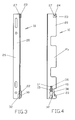
- the Fig. 1 . 3 and 4 show a device according to the invention.
- the console 10 is formed as a continuous rail 20.
- a continuous rail 20 may thus, but need not be provided to realize the invention.
- the rail 20 is designed in its profile substantially L-shaped and has a first leg 25 and a second leg 26.
- the latching element 30 can be arranged only in the receptacle 21 on the first leg 25 of the rail 20.
- the second leg 26 is for mounting on the object, such as a wall.
- both legs 25, 26 such that they each have a receptacle 21 for the latching element 30 as well as means to be fastened to the object. Characterized in that the two legs 25, 26 are configured differently deep, then the distance between the radiator and object by rotating the rail and the use of the respective leg 25, 26 can be varied.
- an upper holding means 23 is provided, which each has a U-shaped recess 24.
- the radiator for example, with him on attachment tabs be hung. Only then must the radiator with its lower portion with the locking element 30 are brought into operative connection. This brings the already explained advantages.
- the upper holding means 23 has a plastic lining 27. This serves the sound decoupling between console 10 and radiator. Since the console 10 is usually, but not necessarily, made of metal, it is possible to avoid that noises between radiator and console 10 are transmitted.
- the latching element 30 in order to effect a sound decoupling between radiator and console 10 in this area, too.
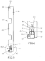
- the locking element 30 is in its assembled state 30.1, as well as off Fig. 2 closer.
- a recess 31 is arranged, in which the radiator with its lower edge of a fastening device, such as a tab or the like, can be introduced.
- the latching element 30 has a stop 33 which rests against a counter stop 11 located on the console 10, as a result of which the latching element 30 can not be lost from the console 10 in the assembled state 30.1.
- the spring 32 pushes the locking element 30 in the illustrated figures upwards, so that the stop 33 and the counter-stop 11 are in operative connection with each other.
- the stop 33 is arranged on the tab 40 and indeed in its end region 41.
- FIGS. 5 and 6 now show the locking element 30 in the disassembled state 30.2.
- the locking element 30 has been pressed down, so to speak, until the projection 34 is in engagement with the counter-projection 12 on the bracket 10.
- the recess 31 has also been pressed down thereby, so that the heating body is no longer arranged in the recess 31. Rather, he is in this embodiment only of the upper holding means 23, which are also formed here as U-shaped recesses 24, held, since it is hooked into this recess 24.
- the locking element 30 Since the transfer of the locking element 30 from the mounting state 30.1 in the disassembled state 30.2 is against the force of the spring 32 and since the locking element 30 at a built-in radiator on the back, which faces the object, the locking element 30 is not alone by hand be transferred to the dismantling state 30.2. Rather, this is a tool necessary, such as a conventional screwdriver. Of course, a corresponding special tool can be used to transfer the locking element 30 in its disassembled state 30.2, in particular to make the locking element 30 in hard to reach places, such as in corners of a room, accessible and operable accordingly.
- the stop 33 and the projection 34 are located at the same place on the locking element 30 and here at the end portion 41 of the tab 40.
- the counter-stop 11 and the counter-projection 12 are on the bracket 10 in different openings 14, 15 arranged. As a result, the mounting state 30.1 and the disassembly state 30.2 are easily definable.
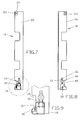
- the function of mounting a radiator in the in the Fig. 1 to 6 shown device, explain the Fig. 7 to 9 , As already mentioned, it is first hung radiator in the or as a U-shaped recesses 24 upper holding means 23. Thereafter, the radiator is pressed with its lower portion against the locking element 30. This has an inclined surface 35, wherein upon pressing the heater against this inclined surface 35, the locking element 30 is pressed against the force of the spring 32 downward. If the latching element 30 is pressed down far enough, the heating element can engage in the recess 31 with its fastening device or its tab. By the force of the spring 32, the locking element 30 is then pushed back up until the stop 33 of the locking element 30th abuts the counter-stop 11 on the console 10.
- this design serves as a lift-out protection and lift-off protection, as it is demanded over and over again, eg by the already mentioned VDI standard.
- the latching element 30 has a cam 36, which is also located in the end region 41 of the tab 40. Like that Fig. 7 to 9 can be seen, the locking element 30 is pressed down as far as the cam 36 comes to rest on the console 10, whereby a contact point 13 is formed. This prevents that the locking element 30 slips down from the console 10.
- the contact point 13 is also located here in the first opening 14 in the console 10 and that in the same first opening 14 on which the counter-shock 11 is disposed, but elsewhere in the first opening 14. Through the two openings 14, 15 can counter-stop 11, counter-projection 12 and contact point 13 on the console 10 easily and inexpensively. Usually, they can simply be punched out of the material of the console 10.
- the spring 32 is shown, which is designed here as an elastic flag.
- the spring 32 is made of a plastic material which has sufficient elasticity.
- polyoxymethylene has proven itself. Other materials are conceivable. It is important that the plastic material has good sliding properties and sufficient elasticity.
- the cam 36 It is designed as a thickening 42 in the end portion 41 of the tab 40. In addition, it has a chamfer 37. This is important when the locking element 30 is to be transferred from its mounting state 30.1 in the disassembled state 30.2. Namely, the locking element 30 from Fig. 10 downwards loaded, so the attachment point 13 slides on the bracket 10 on the chamfer 37 of the cam 36 until the cam 36 no longer comes to rest on the console 10. Rather, the area is then reached at which the projection 34 comes into operative connection with the counter-projection 12 on the bracket 10. This ensures that on the one hand a certain amount of force is necessary to transfer the locking element 30 in its disassembled state 30.2, but that on the other hand, this transfer can also easily vonstatten.
- stop 33 and the projection 34 are formed by the same element. This is virtually the back of the cam 36 in the end portion 41 of the tab 40th
- Fig. 11 is clearly visible that the locking element 30 has an undercut portion 38.
- this undercut area 38 are in Fig. 2 shown edges 17 of the opening 16 of the console 10 can be engaged behind.
- the component having the undercut portion 38 of the locking element 30 is first guided through the opening 16 in the console 10. Thereafter, the locking element 30 is moved in the opening 16 down.
- the undercut portion 38 engages behind the edges 17 of the opening 16.
- a second embodiment of the invention shows Fig. 12 ,
- the peculiarity here is that the recess 19 in the trained as a rail 20 console 10 has a standardized size.
- conventional radiators which are provided with tabs
- different tab heights are common, namely, for example, 20 mm, 25 mm and 40 mm.
- the recess 19 In order to prevent accidental slipping out of the tab of the radiator out of the recess 31, the recess 19 must normally have a height adapted to the tab height.
- the invention proposes in this embodiment, to use an adapter 50. This regulates the height of the recess 19 for the different heights of the corresponding fastening straps.
- the adapter 50 preferably on differently shaped ends 51 which are releasably fastened in different directions on the bracket 10 to take into account the different heights of Edelméperlaschen. It is particularly advantageous here to releasably secure the adapter 50 to the console 10 by means of a clip or latching connection 52.
- the console 10 may have a punched-18 for this purpose.
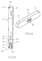
- FIG. 13 A possible construction of an adapter 50 is in Fig. 13 shown.
- the two ends 51 of the adapter 50 are provided for different heights of the radiator tabs, for example, 20 mm and 25 mm.
- the latching connection 52 is arranged eccentrically on the adapter 50, so that depending on the mounting direction of the adapter 50 extends far into the recess 19 and makes the same console 10 for different heights Edelgroperlaschen used. If a heater with particularly high straps, for example, 40 mm, then installed, the adapter 50 is omitted entirely.
Landscapes
- Engineering & Computer Science (AREA)
- Physics & Mathematics (AREA)
- Thermal Sciences (AREA)
- Chemical & Material Sciences (AREA)
- Combustion & Propulsion (AREA)
- Mechanical Engineering (AREA)
- General Engineering & Computer Science (AREA)
- Vehicle Step Arrangements And Article Storage (AREA)
- Connection Of Plates (AREA)
- Insertion Pins And Rivets (AREA)
Applications Claiming Priority (1)
| Application Number | Priority Date | Filing Date | Title |
|---|---|---|---|
| DE201120104109 DE202011104109U1 (de) | 2011-08-05 | 2011-08-05 | Vorrichtung zur Halterung eines Heizkörpers |
Publications (2)
| Publication Number | Publication Date |
|---|---|
| EP2557364A2 true EP2557364A2 (fr) | 2013-02-13 |
| EP2557364A3 EP2557364A3 (fr) | 2018-04-04 |
Family
ID=46275652
Family Applications (1)
| Application Number | Title | Priority Date | Filing Date |
|---|---|---|---|
| EP12003904.5A Withdrawn EP2557364A3 (fr) | 2011-08-05 | 2012-05-18 | Dispositif de fixation d'un radiateur |
Country Status (2)
| Country | Link |
|---|---|
| EP (1) | EP2557364A3 (fr) |
| DE (1) | DE202011104109U1 (fr) |
Families Citing this family (1)
| Publication number | Priority date | Publication date | Assignee | Title |
|---|---|---|---|---|
| BE1021775B1 (nl) * | 2013-10-17 | 2016-01-18 | Rofix Nv, Naamloze Vennootschap | Montagebeugel en montageset voor het bevestigen van een verwarmingselement aan een wand of dergelijke en verwarmingselement voorzien van zo een montageset |
Citations (1)
| Publication number | Priority date | Publication date | Assignee | Title |
|---|---|---|---|---|
| DE19604933A1 (de) | 1996-02-10 | 1997-08-14 | Wemefa Horst Christopeit Gmbh | Haltepratze, insbesondere für eine Konsole zum Befestigen von Heizkörpern |
Family Cites Families (4)
| Publication number | Priority date | Publication date | Assignee | Title |
|---|---|---|---|---|
| BE1006605A6 (nl) * | 1993-01-19 | 1994-10-25 | Rofix Nv | Ophanginrichting voor aan een muur of wand te bevestigen verwarmingsradiatoren. |
| DE4401128C2 (de) * | 1994-01-17 | 1997-07-17 | Gottbehuet Hans Gerd Gmbh | Wandkonsole für die Montage und Demontage eines Heizkörpers |
| EP0733867B1 (fr) * | 1995-03-24 | 1999-12-15 | GIACOMINI S.p.A. | Dispositif pour monter un radiateur contre un mur |
| DE29601329U1 (de) * | 1996-01-26 | 1997-05-28 | Sigarth Ab, Hillerstorp | Vorrichtung zum Befestigen von Gegenständen, wie Heizkörpern an einer Wand |
-
2011
- 2011-08-05 DE DE201120104109 patent/DE202011104109U1/de not_active Expired - Lifetime
-
2012
- 2012-05-18 EP EP12003904.5A patent/EP2557364A3/fr not_active Withdrawn
Patent Citations (1)
| Publication number | Priority date | Publication date | Assignee | Title |
|---|---|---|---|---|
| DE19604933A1 (de) | 1996-02-10 | 1997-08-14 | Wemefa Horst Christopeit Gmbh | Haltepratze, insbesondere für eine Konsole zum Befestigen von Heizkörpern |
Also Published As
| Publication number | Publication date |
|---|---|
| EP2557364A3 (fr) | 2018-04-04 |
| DE202011104109U1 (de) | 2012-11-13 |
Similar Documents
| Publication | Publication Date | Title |
|---|---|---|
| DE202011101112U1 (de) | Befestigungsvorrichtung | |
| EP2881597A1 (fr) | Dispositif de fixation pour câbles | |
| AT13201U1 (de) | Möbelteil mit einer drehmomentübertragenden Welle | |
| AT513109A1 (de) | Schublade | |
| WO2016012081A1 (fr) | Dispositif de fixation d'un rail de montage | |
| EP2566729B1 (fr) | Moteur d'essuie-glace avec élément de désaccouplement | |
| DE102009024813A1 (de) | Befestigungsschelle | |
| DE202010007139U1 (de) | Vorrichtung zur Befestigung eines Moduls zur Nutzung von Sonnenenergie | |
| EP2557364A2 (fr) | Dispositif de fixation d'un radiateur | |
| EP2682681B1 (fr) | Dispositif de fixation pour fixer un corps de refroidissement ou de chauffage | |
| EP2532982B1 (fr) | Dispositif de fixation d'un radiateur maintenu par des attaches de suspension dans une console pourvue d'encoches de réception | |
| AT509757B1 (de) | Vorrichtung zum haltern eines plattenheizkörpers | |
| AT514704B1 (de) | Montagekeil | |
| DE102009010679A1 (de) | Vorhangsystem und Haltevorrichtung für ein Vorhangsystem | |
| DE102015000490A1 (de) | Befestigungselement | |
| EP3095949A1 (fr) | Dispositif de fixation d'un boîtier d'une plinthe d'étanchéité | |
| DE102014115639B4 (de) | Türdichtungssystem | |
| DE9409822U1 (de) | Vorrichtung zur Sicherung der Stoßverbindung von Kabelkanälen mit U-Profilquerschnitt | |
| EP3325744B1 (fr) | Procédé de démontage d'un mécanisme de guidage pour porte coulissante | |
| DE10008685B4 (de) | Aushebesicherung für eine Heizkörperkonsole | |
| DE19828233A1 (de) | Wandkonsole | |
| EP3026983B1 (fr) | Élément de liaison destiné à être intégré à deux éléments de boîtier et agencement de deux éléments de boîtier | |
| DE102007043441A1 (de) | Schlauchstutzen und Schlauchkupplung | |
| EP2620712B1 (fr) | Système anti-levage pour une console | |
| DE102018204087B3 (de) | Türantriebssystem sowie Verfahren zur Montage eines Türantriebssystems an einer Tür |
Legal Events
| Date | Code | Title | Description |
|---|---|---|---|
| PUAI | Public reference made under article 153(3) epc to a published international application that has entered the european phase |
Free format text: ORIGINAL CODE: 0009012 |
|
| AK | Designated contracting states |
Kind code of ref document: A2 Designated state(s): AL AT BE BG CH CY CZ DE DK EE ES FI FR GB GR HR HU IE IS IT LI LT LU LV MC MK MT NL NO PL PT RO RS SE SI SK SM TR |
|
| AX | Request for extension of the european patent |
Extension state: BA ME |
|
| PUAL | Search report despatched |
Free format text: ORIGINAL CODE: 0009013 |
|
| AK | Designated contracting states |
Kind code of ref document: A3 Designated state(s): AL AT BE BG CH CY CZ DE DK EE ES FI FR GB GR HR HU IE IS IT LI LT LU LV MC MK MT NL NO PL PT RO RS SE SI SK SM TR |
|
| AX | Request for extension of the european patent |
Extension state: BA ME |
|
| RIC1 | Information provided on ipc code assigned before grant |
Ipc: F24D 19/02 20060101AFI20180223BHEP |
|
| RBV | Designated contracting states (corrected) |
Designated state(s): AL AT BE BG CH CY CZ DE DK EE ES FI FR GB GR HR HU IE IS IT LI LT LU LV MC MK MT NL NO PL PT RO RS SE SI SK SM TR |
|
| 17P | Request for examination filed |
Effective date: 20180912 |
|
| 17Q | First examination report despatched |
Effective date: 20191001 |
|
| STAA | Information on the status of an ep patent application or granted ep patent |
Free format text: STATUS: THE APPLICATION HAS BEEN WITHDRAWN |
|
| 18W | Application withdrawn |
Effective date: 20191205 |