EP2557539A2 - Bildverarbeitungsvorrichtung, Bildverarbeitungsverfahren und Bildverarbeitungsprogramm - Google Patents
Bildverarbeitungsvorrichtung, Bildverarbeitungsverfahren und Bildverarbeitungsprogramm Download PDFInfo
- Publication number
- EP2557539A2 EP2557539A2 EP12005461A EP12005461A EP2557539A2 EP 2557539 A2 EP2557539 A2 EP 2557539A2 EP 12005461 A EP12005461 A EP 12005461A EP 12005461 A EP12005461 A EP 12005461A EP 2557539 A2 EP2557539 A2 EP 2557539A2
- Authority
- EP
- European Patent Office
- Prior art keywords
- image
- digest
- region
- images
- image processing
- Prior art date
- Legal status (The legal status is an assumption and is not a legal conclusion. Google has not performed a legal analysis and makes no representation as to the accuracy of the status listed.)
- Granted
Links
Images


Classifications
-
- G—PHYSICS
- G06—COMPUTING OR CALCULATING; COUNTING
- G06T—IMAGE DATA PROCESSING OR GENERATION, IN GENERAL
- G06T7/00—Image analysis
- G06T7/20—Analysis of motion
- G06T7/246—Analysis of motion using feature-based methods, e.g. the tracking of corners or segments
-
- G—PHYSICS
- G06—COMPUTING OR CALCULATING; COUNTING
- G06V—IMAGE OR VIDEO RECOGNITION OR UNDERSTANDING
- G06V10/00—Arrangements for image or video recognition or understanding
- G06V10/20—Image preprocessing
- G06V10/26—Segmentation of patterns in the image field; Cutting or merging of image elements to establish the pattern region, e.g. clustering-based techniques; Detection of occlusion
- G06V10/267—Segmentation of patterns in the image field; Cutting or merging of image elements to establish the pattern region, e.g. clustering-based techniques; Detection of occlusion by performing operations on regions, e.g. growing, shrinking or watersheds
-
- G—PHYSICS
- G06—COMPUTING OR CALCULATING; COUNTING
- G06V—IMAGE OR VIDEO RECOGNITION OR UNDERSTANDING
- G06V10/00—Arrangements for image or video recognition or understanding
- G06V10/40—Extraction of image or video features
- G06V10/56—Extraction of image or video features relating to colour
-
- G—PHYSICS
- G06—COMPUTING OR CALCULATING; COUNTING
- G06V—IMAGE OR VIDEO RECOGNITION OR UNDERSTANDING
- G06V20/00—Scenes; Scene-specific elements
- G06V20/40—Scenes; Scene-specific elements in video content
- G06V20/46—Extracting features or characteristics from the video content, e.g. video fingerprints, representative shots or key frames
- G06V20/47—Detecting features for summarising video content
-
- G—PHYSICS
- G06—COMPUTING OR CALCULATING; COUNTING
- G06T—IMAGE DATA PROCESSING OR GENERATION, IN GENERAL
- G06T2207/00—Indexing scheme for image analysis or image enhancement
- G06T2207/10—Image acquisition modality
- G06T2207/10016—Video; Image sequence
-
- G—PHYSICS
- G06—COMPUTING OR CALCULATING; COUNTING
- G06T—IMAGE DATA PROCESSING OR GENERATION, IN GENERAL
- G06T2207/00—Indexing scheme for image analysis or image enhancement
- G06T2207/10—Image acquisition modality
- G06T2207/10024—Color image
-
- G—PHYSICS
- G06—COMPUTING OR CALCULATING; COUNTING
- G06T—IMAGE DATA PROCESSING OR GENERATION, IN GENERAL
- G06T2207/00—Indexing scheme for image analysis or image enhancement
- G06T2207/10—Image acquisition modality
- G06T2207/10068—Endoscopic image
-
- G—PHYSICS
- G06—COMPUTING OR CALCULATING; COUNTING
- G06T—IMAGE DATA PROCESSING OR GENERATION, IN GENERAL
- G06T2207/00—Indexing scheme for image analysis or image enhancement
- G06T2207/30—Subject of image; Context of image processing
- G06T2207/30004—Biomedical image processing
- G06T2207/30028—Colon; Small intestine
-
- G—PHYSICS
- G06—COMPUTING OR CALCULATING; COUNTING
- G06V—IMAGE OR VIDEO RECOGNITION OR UNDERSTANDING
- G06V40/00—Recognition of biometric, human-related or animal-related patterns in image or video data
- G06V40/10—Human or animal bodies, e.g. vehicle occupants or pedestrians; Body parts, e.g. hands
- G06V40/12—Fingerprints or palmprints
- G06V40/1365—Matching; Classification
Definitions
- the present invention relates to an image processing apparatus, an image processing method, and an image processing program that detect a digest image obtained by abstracting a series of images captured in time series.
- imaging is performed for about eight hours at an imaging frame rate of 2 to 4 frames/sec., for example.
- an imaging frame rate of 2 to 4 frames/sec., for example.
- These images may include a redundant scene which is obtained as a result of depicting the same imaging target in a plurality of frames due to continuous imaging performed when the capsule endoscope remains in one place for a while, for example. For this reason, to efficiently evaluate a series of images, it is important to detect a digest image representing a digest of these images.
- WO 2008/041401 discloses an image processing apparatus that extracts an image from a series of continuous images, in which an amount of change between continuous images is calculated in time series, and a predetermined number of images which are arranged in decreasing order of change amount are extracted from the series of images as images including a scene to be detected.
- such a digest image is used for medical diagnosis. Therefore, information should not be missed and there is a demand for high coverage characteristic that allows extensive recognition of information included in a series of images.
- the coverage characteristic of a digest image is not taken into consideration in the conventional technique of detecting a digest image.
- the present invention has been made in view of the above-mentioned circumstances, and has an object to provide an image processing apparatus, an image processing method, and an image processing program that enable detection of a digest image of high coverage characteristic from a series of images captured in time series.
- An image processing apparatus includes: a corresponding region connecting unit (110) that connects regions that depict the same target between a series of images captured in time series, thereby sets at least one connected region; a connected region feature data calculation unit (120, 210) that calculates feature data of the connected region; a digest index value calculation unit (130, 320, 330) that calculates a digest index value corresponding to a degree at which the target depicted in the series of images is aggregated in each image of the series of images, based on the feature data; and a digest image detector (140) that detects a digest image based on the digest index value.
- An image processing method includes: a corresponding region connecting step (S102) of connecting regions depicting the same target among a series of images captured in time series, thereby setting at least one connected region; a connected region feature data calculation step (S103) of calculating feature data of the connected region; a digest index value calculation step (S104) of calculating a digest index value corresponding to a degree at which targets depicted in the series of images are aggregated in each image of the series of images, based on the feature data; and a digest image detection step (S105) of detecting a digest image based on the digest index value.
- An image processing program causes a computer to execute: a corresponding region connecting step (S102) of connecting regions depicting the same target among a series of images captured in time series, thereby setting at least one connected region; a connected region feature data calculation step (S103) of calculating feature data of the connected region; a digest index value calculation step (S104) of calculating a digest index value corresponding to a degree at which targets depicted in the series of images are aggregated in each image of the series of images, based on the feature data; and a digest image detection step (S105) of detecting a digest image based on the digest index value.
- the images to be subjected to image processing in the following embodiments are color images having pixel levels (pixel values) respectively corresponding to color components of R (red), G (green), and B (blue) at positions of pixels, for example.
- the present invention is not limited to the images of the inside of a lumen, but can also be widely applied to the case of detecting a digest image from a series of images obtained by other typical image obtaining apparatuses.
- connect means setting a plurality of regions or pixels as at least one group, by labeling for example, and the term “connected region” means a group consisting of a plurality of regions that depict the same target between a series of images captured in time series in the following embodiments.
- FIG. 1 is a block diagram illustrating a configuration of an image processing apparatus according to a first embodiment of the present invention.
- An image processing apparatus 1 illustrated in FIG. 1 includes a control unit 10 that controls the overall operation of the image processing apparatus 1; an image obtaining unit 20 that obtains image data corresponding to a series of images (hereinafter, referred to also as "time-series images") which are captured in time series by a medical observation apparatus such as a capsule endoscope; an input unit 30 that receives an input signal externally provided; a display unit 40 that performs various kinds of display; a recording unit 50 that records the image data obtained by the image obtaining unit 20 and various programs; and a calculator 100 that executes predetermined image processing on the image data.
- a control unit 10 that controls the overall operation of the image processing apparatus 1
- an image obtaining unit 20 that obtains image data corresponding to a series of images (hereinafter, referred to also as "time-series images") which are captured in time series by a medical observation apparatus such as a
- the control unit 10 is implemented by hardware such as a CPU, and reads various programs stored in the recording unit 50 to transfer an instruction or data to each of units, which constitute the image processing apparatus 1, according to the image data received from the image obtaining unit 20 or an actuating signal received from the input unit 30, for example, thereby controlling the overall operation of the image processing apparatus 1 in an integrated manner.
- the image obtaining unit 20 is appropriately formed according to a mode of a system including the medical observation apparatus.
- the medical observation apparatus is a capsule endoscope and when a portable recording medium is used to deliver the image data from the medical observation apparatus, the image obtaining unit 20 is formed of a reader device which is detachably mounted with the recording medium and which reads the stored image data representing images of the inside of a lumen.
- the image obtaining unit 20 is formed of a communication device or the like to be connected to the server, and obtains the image data representing the images of the inside of a lumen through data communication with the server.
- the image obtaining unit 20 may be formed of an interface device or the like that receives an image signal through a cable from the medical observation apparatus such as an endoscope.
- the input unit 30 is implemented by an input device, such as a keyboard, a mouse, a touch panel, or various switches, for example, and outputs the received input signal to the control unit 10.
- an input device such as a keyboard, a mouse, a touch panel, or various switches, for example, and outputs the received input signal to the control unit 10.
- the display unit 40 is implemented by a display device such as an LCD or an EL display, and displays various screens including the images of the inside of a lumen, under the control of the control unit 10.
- the recording unit 50 is implemented by various IC memories such as flash memories which can be updated and recorded, such as a ROM and a RAM, a hard disk to be built in or connected with a data communication terminal, an information recording medium, such as a CD-ROM, a reading device that reads the recording medium, and the like.
- the recording unit 50 stores the image data representing the images of the inside of a lumen, which are obtained by the image obtaining unit 20, as well as programs for causing the image processing apparatus 1 to operate and for causing the image processing apparatus 1 to execute various functions, data used during the execution of these programs, and the like.
- the recording unit 50 stores an image processing program 51 for executing processing of detecting a digest image from time-series images.
- the calculator 100 is implemented by hardware such as a CPU, and reads the image processing program 51 to thereby perform image processing on the image data corresponding to the time-series images, and performs various calculation processes for detecting a digest image from the time-series images.
- the calculator 100 includes a corresponding region connecting unit 110 that connects regions depicting the same target among a series of time-series images, thereby sets at least one connected region; a connected region feature data calculation unit 120 that calculates feature data of each connected region; a digest index value calculation unit 130 that calculates a digest index value based on the feature data; a digest image detector 140 that detects a digest image based on the digest index value; and a repetition controller 150 that controls repetition of processing in each of the digest index value calculation unit 130 and the digest image detector 140.
- a corresponding region connecting unit 110 that connects regions depicting the same target among a series of time-series images, thereby sets at least one connected region
- a connected region feature data calculation unit 120 that calculates feature data of each connected region
- a digest index value calculation unit 130 that calculates a digest index value based on the feature data
- a digest image detector 140 that detects a digest image based on the digest index value
- a repetition controller 150 that controls repetition of processing in each of the digest index
- the corresponding region connecting unit 110 includes a region correlating unit 111 that correlates regions included in each image among the images continuous in time series, and connects the regions depicting the same target in each image and between images based on the correlation result. More specifically, the region correlating unit 111 includes an optical flow calculation unit 111a that calculates an optical flow between the images that are continuous in time series, and correlates the regions between the images based on the optical flow.
- the connected region feature data calculation unit 120 includes a connected region volume calculation unit 121 that calculates the volume of each connected region which is the sum of the number of pixels included in each connected region. The volume of each connected region is used as the feature data.
- the digest index value calculated by the digest index value calculation unit 130 corresponds to a degree at which the targets depicted in the time-series images are aggregated in each image among the time-series images.
- the digest index value calculation unit 130 includes a feature data sum calculation unit 131 that calculates, for each image, the sum of the feature data of each connected region included in each image, and the sum of the feature data is used as the digest index value.
- the repetition controller 150 includes a digest image number calculation unit 151 that calculates the number of detected digest images, and controls repetition of processing in each of the digest index value calculation unit 130 and the digest image detector 140 according to the number of digest images.
- FIG. 2 is a flowchart illustrating the processing executed by the image processing apparatus 1.
- step S101 the image obtaining unit 20 obtains a series of images of the inside of a lumen (hereinafter referred to simply as "images") which are obtained by capturing images of the inside of a lumen of a subject in times series, and stores the obtained images in the recording unit 50.
- the calculator 100 sequentially reads the images to be subjected to image processing from the recording unit 50.
- the corresponding region connecting unit 110 connects pixels depicting the same target in a plurality of images.
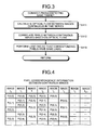
- FIG. 3 is a flowchart illustrating details of the processing (step S102) of connecting the pixels depicting the same target.
- the optical flow calculation unit 111a calculates the optical flow between the images that are continuous in time series.
- the term "optical flow” herein described refers to vector data representing a shift amount obtained by correlating the same targets in two images captured at different times.
- the optical flow is calculated using a well-known optical flow calculation method (more specifically, block matching method or a gradient method) with respect to a G component in a pixel value of the image of the inside of a lumen (see: CG-ARTS Society, "Digital Image Processing," pages 243 to 245 )).
- the optical flow may be calculated using a well-known technique such as Lucas-Kanade tracking (see: B. D. Lucas and T. Kanade, "An Iterative Image Registration Technique with an Application to Stereo Vision," Proceedings of the 7th International Joint Conference on Artificial Intelligence, pages 674-679, 1981 ).
- the G component is used because the G component is close to the light absorbing band of blood and thus is excellent in representation of configuration information of an image of the inside of a lumen, such as pathology, mucosa, a boundary between contents, and the like.
- the G component instead of the G component, other color components (R component or B component) of pixel values, and values secondarily calculated from the pixel values by well-known conversion, specifically, luminance, color difference (YCbCr conversion), hue, chroma, brightness (HSI conversion), color ratio, and the like may also be used.
- the region correlating unit 111 correlates the pixels between the continuous images based on the optical flow. Specifically, the following processing is carried out. That is, the region correlating unit 111 obtains a corresponding coordinate (x t1 , y t1 ) (where x t1 and y t1 are real numbers) in the subsequent image in time series with respect to a pixel coordinate (x t0 , y t0 ) (where x t0 and y t0 are natural numbers) of the previous image in times series based on the optical flow, and also obtains a corresponding coordinate (x t0 ', y t0 ') (where x t0 ' and y t0 ' are real numbers) in the previous image in time series with respect to a pixel coordinate (x t1 ', y t1 ') (where x t1 ' and y t1 ' are natural numbers) in the subsequent image in time series. Then
- the region correlating unit 111 correlates a predetermined number of pixels in one image, the coordinate of which is closer to the pixel coordinate, with the pixel coordinate. Then, the other pixels are assumed as pixels of a target portion which is not depicted in the other image while being depicted in one image, and thus the other pixels are not correlated.
- the coordinates are not necessarily correlated in one-to-one correspondence. This is because the images may be enlarged or reduced depending on the distance between the capsule endoscope and the imaging target (for example, a mucosa surface) or the angle.
- the correspondence in the forward direction in time series (the coordinate of the subsequent image corresponding to the pixel of the previous image) and the correspondence in the opposite direction (the coordinate of the previous image corresponding to the pixel of the subsequent image) are detected so as to increase the reliability of the corresponding coordinates. Note that in the first embodiment, only the correspondence in one of the forward direction and the opposite direction in time series may be detected.
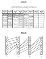
- FIG. 4 is a table illustrating an example of pixel correspondence information between continuous images.
- P (x, y) represents a pixel located at a coordinate (x, y) in each image.
- This pixel correspondence information indicates that pixels written in adjacent rows (for example, a pixel P (0, 1) of an image I 0 and P (0, 1) and P (0, 2) of an image I 1 ) are corresponding pixels in adjacent columns. Note that the case where one of the adjacent rows in the adjacent columns is blank indicates that there is no corresponding pixel.
- the corresponding region connecting unit 110 performs labeling so that the corresponding pixels have the same label. More specifically, the corresponding region connecting unit 110 first sets a label value, which is set to a certain pixel, to all corresponding pixels based on the pixel correspondence information. Next, a new label value is set to pixels with no label value set thereto, and the same processing described above is carried out. Such processing is sequentially repeated, thereby performing labeling on all the pixels. Furthermore, the corresponding region connecting unit 110 sets the aggregation of the pixels having the same label value set thereto, as the connected region of the pixels depicting the same target.
- FIG. 5 is a table illustrating an example of results (connected region labeling information) of labeling based on the pixel correspondence information illustrated in FIG. 4 .
- each value shown next to a colon following each pixel P (x, y) represents a label value set to the pixel P (x, y).
- FIG. 6 is a model diagram illustrating regions of pixels connected as a result of labeling processing in four images I 0 to I 3 that are continuous in time series.
- pixels P 00 to P 07 , P 10 to P 17 , P 20 to P 27 , and P 30 to P 37 which are included in the images I 0 to I 3 are one-dimensionally represented by pixel columns as a simulation.
- pixels connected by a line are the pixels constituting one connected region.
- steps S111 to S113 description has been made of the case where the processing (pixel correspondence processing and pixel connection processing) for each pixel is executed, the same processing may be performed for each small region including a plurality of pixels.
- each image is divided into small regions in advance based on the edge strength or the like.
- a technique using a ridge of edge strength as a boundary for example, see WO 2006/080239
- watershed algorithm see: Luc Vincent and Pierre Soille, "Watersheds in Digital Spaces: An Efficient Algorithm Based on Immersion Simulations," IEEE Transactions on Pattern Analysis and Machine Intelligence, Vol. 13, No. 6, pp. 583-598, June 1991 ), and the like may be used.
- the connected region feature data calculation unit 120 calculates feature data of each connected region. More specifically, the connected region volume calculation unit 121 calculates the sum of the number of pixels included in each connected region as the connected region volume. The connected region feature data calculation unit 120 uses the connected region volume as the feature data of each connected region.
- FIG. 7 is a model diagram illustrating results of calculating the feature data with respect to each connected region illustrated in FIG. 6 .
- Each encircled value illustrated in FIG. 7 represents feature data (connected region volume in the first embodiment) of each connected region (connected region including pixels connected by a line on which a circle is located).
- the volume (the number of pixels) of the connected region including the pixel P 07 of the image I 0 , the pixel P 14 of the image I 1 , and the pixels P 20 and P 21 of the image I 2 is "4.”
- the digest index value calculation unit 130 calculates the digest index value of each image based on the feature data of the connected region. More specifically, the feature data sum calculation unit 131 calculates, for each image, the sum of the feature data of each connected region included in each image. The sum of the feature data of each connected region is used as the digest index value.
- a digest index value E(I n ) of the image In is given by the following expression (1).
- E I n ⁇ F L i
- the right side represents the sum of feature data F(L i ) (which is the connected region volume in the first embodiment) of a connected region L i to which a label value "i" included in the image In is set.
- the digest index value E(I n ) is given by the following expressions.
- E I 0 F L 1 + F L 2 + F L 3 + F L 5 + ...
- E I 1 F L 1 + F L 2 + F L 4 + F L 5 + ...
- E I 2 F L 1 + F L 2 + F L 4 + ...
- E I 3 F L 2 + F L 4 + F L 6 + ...
- the digest image detector 140 detects an image having a maximum digest index value as a digest image. This is because an image having a larger digest index value, which is obtained by the calculation method described above, is considered to be an image in which the targets depicted in time-series images are more aggregated. For example, the image I 1 whose digest index value E(I n ) is maximum (24) among the four images is detected as the digest image from the images I 0 to I 3 illustrated in FIG. 7 .
- FIG. 8 is a model diagram illustrating relations between the digest index values and the aggregation of the time-series images.
- the pixels included in the image I 1 and the pixels in the other images I 0 , I 2 , and I 3 corresponding to these pixels are shaded.
- the pixels in the image I 1 correspond to the most pixels in the images I 0 and I 2 . That is, the image I 1 includes the most part of the targets depicted in the images I 0 and I 2 , and thus it can be said that the targets depicted in the time-series images I 0 to I 3 are most aggregated.
- step S106 the digest image number calculation unit 151 of the repetition controller 150 calculates the number of detected digest images (detected number).
- the repetition controller 150 determines whether the number of digest images reaches a predetermined value.
- a predetermined value a desired number can be preliminarily set by a user.
- step S107 When the number does not reach the predetermined value (step S107: No), the repetition controller 150 recognizes the target corresponding to the connected region included in the detected digest image, as the detected target, and sets the feature data of the connected region of the digest image to zero (step S108). After that, the processing returns to step S104. In this case, the processing (steps S104 and S105 and subsequent steps) for undetected targets in each of the digest index value calculation unit 130 and the digest image detector 140 is repeatedly executed.
- the reason that the digest image of high coverage characteristic for the targets depicted in the time series images can be detected by such repetition processing will be described with reference to FIG. 9 .
- the feature data of the connected region included in the image I 1 which is detected as the digest image, is set to zero. Further, all pixels corresponding to the pixels within the image I 1 , that is, the pixels depicting the targets aggregated in the digest image are shaded. Thus, it is apparent that the image I 3 depicting the most part of uncovered targets is desirably subsequently detected as the digest image.
- the image I 3 having the largest (7) digest index value E(I n ) is determined as the digest image to be subsequently detected (step S105 after the repetition). This also matches the concept illustrated in the model diagram of FIG. 9 .
- the digest image of high coverage characteristic for the targets depicted in the time-series images can be detected by further repeating such processing.
- step S107 when the number of digest images reaches the predetermined value (step S107: Yes), the processing shifts to step S109.
- the calculator 100 outputs the detection result of the digest image to the display unit 40 and stores the detection result in the recording unit 50. After that, the processing of the image processing apparatus 1 ends.
- the connected region is obtained by connecting the regions depicting the same target in the time-series images, and the digest images in which the targets depicted in the time-series images are aggregated are sequentially detected based on the sum of the volumes of the connected regions included in each image, thereby enabling detection of the digest image of high coverage characteristic for the diagnosis target.
- the repetition controller 150 repeatedly executes the processing in each of the digest index value calculation unit 130 and the digest image detector 140.
- the digest image of high coverage characteristic can be detected also by at least one processing in each of the digest index value calculation unit 130 and the digest image detector 140.
- An image processing apparatus includes a repetition controller 160 including a coverage calculation unit 161, instead of the repetition controller 150 illustrated in FIG. 1 .
- the coverage calculation unit 161 calculates the coverage of the targets depicted in the time-series images covered by the detected digest image.
- the repetition controller 160 controls repetition of the processing in each of the digest index value calculation unit 130 and the digest image detector 140 according to this coverage.
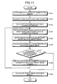
- FIG. 11 is a flowchart illustrating the processing executed by the image processing apparatus according to the first modified example.
- the processing in steps S101 to S105, S108, and S109 is similar to that of the first embodiment.
- step S126 the coverage calculation unit 161 calculates a coverage C R by the detected digest image by using the following expression (2).
- C R the sum of feature data of connected areas existing in a digest image the sum of feature data of all connected areas
- step S127 the repetition controller 160 determines whether the coverage C R thus calculated is equal to or greater than a predetermined value.
- a predetermined value can be preliminarily set by the user.
- step S127 No
- the repetition controller 160 sets the feature data of the connected region included in the detected digest image to zero (step S108). After that, the processing returns to step S104. In this case, the processing (steps S104 and S105 and subsequent steps) in each of the digest index value calculation unit 130 and the digest image detector 140 is repeatedly executed.
- step S127: Yes when the coverage is equal to or greater than the predetermined value (step S127: Yes), the processing shifts to step S109.
- the coverage by the detected digest image is calculated simultaneously with the detection of the digest image, and the control for repetition of the processing is executed according to the coverage, thereby enabling detection of the digest image having a predetermined coverage or more.
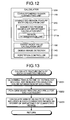
- FIG. 12 is a block diagram illustrating a configuration of a calculator included in an image processing apparatus according to the second embodiment. Note that the configurations and operations other than the calculator of the image processing apparatus according to the second embodiment are similar to those illustrated in FIG. 1 .
- a calculator 200 illustrated in FIG. 12 includes a connected region feature data calculation unit 210 including a connected region degree-of-importance calculation unit 211, instead of the connected region feature data calculation unit 120 illustrated in FIG. 1 .
- the configurations and operations of the other components are similar to those of the first embodiment.
- the connected region degree-of-importance calculation unit 211 includes a region determination unit 211a that determines each region in each image of a series of time-series images so as to, for example, classify the regions depending on the degree of importance in diagnosis, and calculates the degree of importance of each connected region based on the determination result.
- the connected region feature data calculation unit 210 uses the calculated degree of importance as the feature data of the connected region.
- the region determination unit 211a determines each region in each image as one of a region to be detected (detection target region), a region to be examined (examination target region), and a region unnecessary for examination (non-examination-target region).
- the region to be detected corresponds to a pathology portion
- the region to be examined corresponds to a mucosal region
- the region unnecessary for examination corresponds to a non-mucosal region.
- step S103 processing executed by the image processing apparatus according to the second embodiment.
- FIG. 13 is a flowchart illustrating the processing of calculating feature data of each connected region which is executed by the connected region feature data calculation unit 210.
- the region determination unit 211a determines each of the pixels as one of the categories of pathology, mucosa, and non-mucosa, based on color information of each pixel (step S201). Note that various well-known methods may be employed as the method of determining the categories (pathology, mucosa, non-mucosa, and the like) of the pixels of the images of the inside of a lumen based on the color information.
- an image is divided into regions by hierarchically classifying images of the inside of a lumen based on a value of a specific waveform component (for example, R component) of each pixel within the images of the inside of the lumen;
- the pixel feature data for example, values of R, G, and B components of the pixels, and values of luminance, color difference, hue, chroma, brightness, color ratio, and the like which are secondarily calculated based on these components
- the cluster of a pathology portion is discriminated by comparing each cluster with a predetermined cluster discrimination criterion; and the pixel belonging to the cluster of the pathology portion are specified as a pathology pixel (see Japanese Laid-open Patent Publication No. 2010-113616 ).
- the connected region degree-of-importance calculation unit 211 performs weighting on each pixel for each category. This weighting is set such that the pathology pixel has the highest weight; the mucosa pixel has the second highest weight; and the non-mucosa pixel has the lowest weight. This is because the degree of importance of pixels to be covered in the digest image is determined such that the pathology pixel has the highest degree of importance, the mucosa pixel has the second highest degree of importance, and the non-mucosa pixel has the lowest degree of importance.
- a weight 2 is set to the pathology pixel; a weight 1 is set to the mucosa pixel; and a weight 0 is set to the non-mucosa pixel.
- the connected region degree-of-importance calculation unit 211 calculates the sum of the weights of the pixels included in each connected region as the degree of importance of connected region. This degree of importance of connected region is used as the feature data in the case of calculating the digest index value of each image (step S104).
- the degree of importance is taken into consideration based on the discrimination results of the regions (the detection target region, the examination target region, and the non-examination-target region) to which the pixels in each image belong. This enables detection of the digest image of high coverage characteristic for the important diagnosis target depicted in the time-series images.
- pixels are discriminated by the processing for each pixel in the second embodiment, but the same processing may be carried out for each small region including a plurality of pixels.
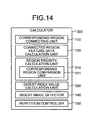
- FIG. 14 is a block diagram illustrating a configuration of a calculator included in an image processing apparatus according to the third embodiment. Note that the configurations and operations other than the calculator of the image processing apparatus according to the third embodiment are similar to those illustrated in FIG. 1 .
- a calculator 300 illustrated in FIG. 14 further includes a region priority calculation unit 310 added to the calculator 100 illustrated in FIG. 1 , and also includes a digest index value calculation unit 320 instead of the digest index value calculation unit 130 illustrated in FIG. 1 .
- the configurations and operations of the other components are similar to those of the first embodiment.
- the region priority calculation unit 310 calculates a priority of detection of digest images based on the visibility with respect to the regions in each image of a series of time-series images. More specifically, the region priority calculation unit 310 includes a corresponding region comparison unit 311 that compares regions belonging to the same connected region between different images, and calculates the priority described above based on the comparison result of the corresponding region comparison unit 311.
- the digest index value calculation unit 320 calculates the digest index value based on the priority calculated by the region priority calculation unit 310 and the region feature data calculated by the connected region feature data calculation unit 120.
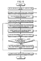
- FIG. 15 is a flowchart illustrating the processing executed by the image processing apparatus according to the third embodiment.
- the processing in steps S101 to S103 and S105 to S109 are similar to those of the first embodiment.
- step S301 subsequent to step S103 the region priority calculation unit 310 calculates the priority based on the visibility with respect to the regions in each image.
- FIG. 16 is a flowchart illustrating details of the processing of calculating the priority based on the visibility (step S301).
- step S311 the corresponding region comparison unit 311 compares the areas of each region included in the same connected region (hereinafter referred to as "comparison target region") between different images.
- FIG. 17 is a model diagram illustrating an example of comparing the areas of comparison target regions. In FIG. 17 , attention is paid to one connected region included in the different images I 0 to I 2 , and the comparison target regions (pixels) included in the connected region are shaded.
- S(I n ) normalized so that the maximum area of the comparison target regions becomes 1
- the corresponding region comparison unit 311 calculates the area index value for all the connected regions as the target, thereby obtaining the area index value for each region included in the same connected region in each image.
- the corresponding region comparison unit 311 compares the positions of the comparison target regions in each image between different images.
- the corresponding region comparison unit 311 calculates the position index value that becomes closer to 1 as the comparison target region approaches the center of the image, by using the following expression (3) based on a barycentric coordinate (x g , y g ) of the comparison target region and a central coordinate (x c , y c ) of the image.
- position index value 1 - x g - x c 2 + y g - y c 2 x c 2 + y c 2
- the corresponding region comparison unit 311 calculates the position index value for all connected regions as the target, thereby obtaining the position index value for each region included in the same connected region in each image.
- the corresponding region comparison unit 311 compares noise amounts of the comparison target regions in each image between different images.
- comparison target regions having smaller noise amounts have higher visibility.
- the noise that lowers the visibility includes high-frequency component noise having a predetermined frequency or higher. Therefore, the corresponding region comparison unit 311 performs processing of a well-known high-pass filter (see: CG-ARTS Society, "Digital Image Processing," pp. 133 to 136 ) on each pixel within the comparison target region, and calculates an average value within the comparison target region of the output values (pixel values) obtained after the high-pass filter processing, as the amount of noise.
- a well-known high-pass filter see: CG-ARTS Society, "Digital Image Processing," pp. 133 to 136
- the corresponding region comparison unit 311 calculates the noise amount index value which becomes closer to 1 as the noise amount of the comparison target region decreases, by using the following expression (4).
- noise amount index value 1 - N - min N max N - min N
- N represents the amount of noise of the comparison target region which is a target of calculating the noise amount index value
- max(N) represents a maximum noise amount of the comparison target region included in the same connected region
- min(N) represents a minimum noise amount of the comparison target region included in the same connected region.
- the corresponding region comparison unit 311 calculates the noise amount index value for all connected regions as the target, thereby obtaining the noise amount index value for each region included in the same connected region in each image.
- the corresponding region comparison unit 311 compares resolutions of the comparison target regions in each image between different images.
- comparison target regions having higher resolutions have higher visibility.
- the resolution becomes higher when the number of higher-frequency components, except for high-frequency components corresponding to noise, is large, that is, when the number of intermediate frequency components is large. Therefore, the corresponding region comparison unit 311 performs processing of a well-known bandpass filter (see: CG-ARTS Society, "Digital Image Processing," p. 136) on each pixel within the comparison target region, and calculates the average value within the comparison target region of the output values (pixel values) obtained after the bandpass filter processing, as the resolution evaluation amount.
- a desired value is preliminarily set by the user as an intermediate frequency component to be extracted by a bandpass filter.
- the corresponding region comparison unit 311 calculates the resolution index value which becomes closer to 1 as the resolution evaluation amount of the comparison target region increases, by using the following expression (5).
- resolution index value R - min R max R - min R
- R represents a resolution evaluation amount of the comparison target region which is a target of calculating the resolution index value
- max(R) represents a maximum resolution evaluation amount of the comparison target region included in the same connected region
- min(R) represents a minimum resolution evaluation amount of the comparison target region included in the same connected region.
- the corresponding region comparison unit 311 calculates the resolution index value for all connected regions as the target, thereby obtaining the resolution index value for each region included in the same connected region in each image.
- step S315 the corresponding region comparison unit 311 compares the brightness of the comparison target region in each image.
- the corresponding region comparison unit 311 calculates an average luminance value of the comparison target region.
- a brightness index value which becomes closer to 1 as the brightness of the comparison target region becomes closer to a predetermined range is calculated by using the following expression (6). Note that a desired range is preliminarily set by the user as the range of the brightness.
- brightness index value ⁇ v min_th : 0 ⁇ V ⁇ min_ th 1 : min_ th ⁇ V ⁇ max_ th - V - max ⁇ V max ⁇ V - max_ th : max_ th ⁇ V ⁇ max ⁇ V
- V represents an average luminance value of the comparison target region which is a target of calculating the brightness index value
- min_th represents a lower-limit luminance value in consideration of the visibility
- max_th represents an upper-limit luminance value in consideration of the visibility
- maxV represents an upper limit value of the luminance value that can be taken.
- the corresponding region comparison unit 311 calculates the brightness index value for all connected regions as the target, thereby obtaining the brightness index value for each region included in the same connected region in each image.
- step S316 the region priority calculation unit 310 calculates the priority of each comparison target region based on the comparison results of the area, position, noise amount, resolution, and brightness. This priority is given by the following expression (7).
- Priority W A ⁇ area index value + W P ⁇ position index value + W W ⁇ noise amount index value + W R ⁇ resolution index value + W V ⁇ brightness index value
- W A , W P , W N , W R , and W V respectively represent weights on index values of area, position, noise amount, resolution, and brightness, and satisfy the following expression (8).
- W A + W P + W N + W R + W V 1
- step S302 the digest index value calculation unit 320 calculates the digest index value of each image based on the priority and the feature data of the connected region. Specifically, the average value of the priorities of the pixels included in the connected region having feature data other than zero is calculated for each image. As a result, when a larger number of regions having high priorities are present in each image, the digest index value becomes higher.
- the digest index value in consideration of the priority based on the visibility of each region in each image is calculated, and the digest image is detected based on this digest index value. This enables detection of the digest image which has excellent visibility with respect to the diagnosis target depicted in the time-series images and in which the coverage characteristic is taken into consideration.
- An image processing apparatus includes a digest index value calculation unit 330 including a weighting priority average calculation unit 331, instead of the digest index value calculation unit 320 illustrated in FIG. 14 .
- the weighting priority average calculation unit 331 calculates the priority based on the visibility with respect to the comparison target region in each image in step S301 illustrated in FIG. 15 , and then calculates the weighting priority by multiplying the priority calculated for pixels included in each image by the feature data of the connected region including the pixels. Further, the weighting priority average calculation unit 331 calculates, for each image, the average value of the weighting priorities of the pixels included in each image. This average value of the weighting priorities is used as the digest index value.
- weighting is performed by multiplying the priority based on the visibility of the region in each image by the feature data of the connected region, thereby enabling detection of the digest image having excellent visibility with respect to the diagnosis target depicted in the time-series images and having further improved coverage characteristic.
- pixels are discriminated by the processing for each pixel in the third embodiment and the second modified example, but the same processing may be performed for each small region including a plurality of pixels.
- the image processing apparatuses according to the first to third embodiments and the modified examples thereof described above can be implemented by causing a computer system, such as a personal computer or a work station, to execute an image processing program stored in a recording medium. Further, such a computer system may be used to be connected to a device, such as another computer system or a server, through a public line such as a local area network/wide area network (LAN/WAN) or the Internet.
- LAN/WAN local area network/wide area network
- the image processing apparatuses according to the first to third embodiments may be configured to obtain image data representing images of the inside of a lumen through these networks, output the results of image processing to various output devices (a viewer, a printer, and the like) connected through these networks, or store the results of image processing in a storage device (a recording medium and a reading device for reading the reading medium, and the like) connected through these networks.
- the index value representing the degree of aggregation of targets depicted in time-series images is calculated based on the feature data of each connected region set by correlating the regions depicting the same target among a series of images captured in time series, and a digest image is detected based on the index value. This enables detection of the digest image of high coverage characteristic for the targets depicted in the series of images.
Landscapes
- Engineering & Computer Science (AREA)
- Physics & Mathematics (AREA)
- General Physics & Mathematics (AREA)
- Multimedia (AREA)
- Theoretical Computer Science (AREA)
- Computer Vision & Pattern Recognition (AREA)
- Endoscopes (AREA)
- Image Analysis (AREA)
- Television Signal Processing For Recording (AREA)
- Image Processing (AREA)
Applications Claiming Priority (1)
| Application Number | Priority Date | Filing Date | Title |
|---|---|---|---|
| JP2011167268A JP5784404B2 (ja) | 2011-07-29 | 2011-07-29 | 画像処理装置、画像処理方法、及び画像処理プログラム |
Publications (3)
| Publication Number | Publication Date |
|---|---|
| EP2557539A2 true EP2557539A2 (de) | 2013-02-13 |
| EP2557539A3 EP2557539A3 (de) | 2016-09-07 |
| EP2557539B1 EP2557539B1 (de) | 2019-03-13 |
Family
ID=46875608
Family Applications (1)
| Application Number | Title | Priority Date | Filing Date |
|---|---|---|---|
| EP12005461.4A Active EP2557539B1 (de) | 2011-07-29 | 2012-07-26 | Bildverarbeitungsvorrichtung, Bildverarbeitungsverfahren und Bildverarbeitungsprogramm |
Country Status (4)
| Country | Link |
|---|---|
| US (1) | US9773185B2 (de) |
| EP (1) | EP2557539B1 (de) |
| JP (1) | JP5784404B2 (de) |
| CN (1) | CN103177437B (de) |
Cited By (1)
| Publication number | Priority date | Publication date | Assignee | Title |
|---|---|---|---|---|
| CN105142493A (zh) * | 2013-08-30 | 2015-12-09 | 奥林巴斯株式会社 | 图像管理装置 |
Families Citing this family (12)
| Publication number | Priority date | Publication date | Assignee | Title |
|---|---|---|---|---|
| WO2011135573A1 (en) * | 2010-04-28 | 2011-11-03 | Given Imaging Ltd. | System and method for displaying portions of in-vivo images |
| KR101704982B1 (ko) * | 2013-07-29 | 2017-02-08 | 제이에프이 스틸 가부시키가이샤 | 이상 검지 방법 및 고로 조업 방법 |
| US9342881B1 (en) * | 2013-12-31 | 2016-05-17 | Given Imaging Ltd. | System and method for automatic detection of in vivo polyps in video sequences |
| JP5937286B1 (ja) * | 2014-09-29 | 2016-06-22 | オリンパス株式会社 | 画像処理装置、画像処理方法、及び画像処理プログラム |
| FR3027727B1 (fr) * | 2014-10-22 | 2016-12-09 | Socomec Sa | Chambre de coupure d'arc electrique |
| JP6058240B1 (ja) * | 2015-04-27 | 2017-01-11 | オリンパス株式会社 | 画像解析装置、画像解析システム、画像解析装置の作動方法 |
| CN110770760B (zh) | 2017-05-19 | 2024-01-12 | 渊慧科技有限公司 | 视觉交互网络系统及其方法、训练方法和计算机存储介质 |
| WO2019078237A1 (ja) | 2017-10-18 | 2019-04-25 | 富士フイルム株式会社 | 医療画像処理装置、内視鏡システム、診断支援装置、並びに医療業務支援装置 |
| CN113038868B (zh) * | 2018-11-14 | 2024-10-11 | 富士胶片株式会社 | 医疗图像处理系统 |
| TWI703348B (zh) * | 2018-12-06 | 2020-09-01 | 宏達國際電子股份有限公司 | 影像處理系統及影像處理方法 |
| US10799090B1 (en) | 2019-06-13 | 2020-10-13 | Verb Surgical Inc. | Method and system for automatically turning on/off a light source for an endoscope during a surgery |
| JP7348845B2 (ja) * | 2020-01-09 | 2023-09-21 | 富士フイルムヘルスケア株式会社 | 超音波診断装置およびプログラム |
Citations (2)
| Publication number | Priority date | Publication date | Assignee | Title |
|---|---|---|---|---|
| WO2006080239A1 (ja) | 2005-01-31 | 2006-08-03 | Olympus Corporation | 画像処理装置、顕微鏡システム、及び領域特定プログラム |
| WO2008041401A1 (fr) | 2006-10-02 | 2008-04-10 | Olympus Corporation | Dispositif, procédé et programme de traitement d'image |
Family Cites Families (16)
| Publication number | Priority date | Publication date | Assignee | Title |
|---|---|---|---|---|
| JP2000261741A (ja) * | 1999-03-04 | 2000-09-22 | Nippon Hoso Kyokai <Nhk> | 静止画抽出装置および静止画抽出のためのプログラム記憶媒体 |
| US7043474B2 (en) * | 2002-04-15 | 2006-05-09 | International Business Machines Corporation | System and method for measuring image similarity based on semantic meaning |
| JP4418400B2 (ja) * | 2005-05-20 | 2010-02-17 | オリンパスメディカルシステムズ株式会社 | 画像表示装置 |
| JP4921858B2 (ja) * | 2006-06-07 | 2012-04-25 | オリンパス株式会社 | 画像処理装置および画像処理プログラム |
| JP5121204B2 (ja) * | 2006-10-11 | 2013-01-16 | オリンパス株式会社 | 画像処理装置、画像処理方法、および画像処理プログラム |
| EP2157790A4 (de) * | 2007-06-21 | 2012-06-20 | Olympus Corp | Bildanzeigeeinrichtung und bildanzeigeprogramm |
| JP4959445B2 (ja) * | 2007-07-04 | 2012-06-20 | オリンパス株式会社 | 画像処理装置および画像処理プログラム |
| WO2009005141A1 (ja) * | 2007-07-05 | 2009-01-08 | Nec Corporation | 物体領域検出装置、物体領域検出システム、物体領域検出方法及びプログラム |
| JP5203648B2 (ja) * | 2007-07-20 | 2013-06-05 | オリンパス株式会社 | 画像抽出装置および画像抽出プログラム |
| JP5191240B2 (ja) * | 2008-01-09 | 2013-05-08 | オリンパス株式会社 | シーン変化検出装置およびシーン変化検出プログラム |
| JP5374135B2 (ja) * | 2008-12-16 | 2013-12-25 | オリンパス株式会社 | 画像処理装置、画像処理装置の作動方法および画像処理プログラム |
| JP5457688B2 (ja) * | 2009-02-04 | 2014-04-02 | オリンパス株式会社 | 画像処理装置、画像処理プログラムおよび画像処理方法 |
| JP5533861B2 (ja) * | 2009-04-30 | 2014-06-25 | ソニー株式会社 | 表示制御装置、表示制御方法、及び、プログラム |
| JP5214533B2 (ja) * | 2009-05-21 | 2013-06-19 | 富士フイルム株式会社 | 人物追跡方法、人物追跡装置および人物追跡プログラム |
| JP5220705B2 (ja) * | 2009-07-23 | 2013-06-26 | オリンパス株式会社 | 画像処理装置、画像処理プログラムおよび画像処理方法 |
| US8611621B2 (en) * | 2010-09-08 | 2013-12-17 | Given Imaging Ltd. | System and method for automatic detection of in vivo contraction video sequences |
-
2011
- 2011-07-29 JP JP2011167268A patent/JP5784404B2/ja active Active
-
2012
- 2012-07-18 US US13/551,798 patent/US9773185B2/en active Active
- 2012-07-26 EP EP12005461.4A patent/EP2557539B1/de active Active
- 2012-07-26 CN CN201210262749.4A patent/CN103177437B/zh active Active
Patent Citations (2)
| Publication number | Priority date | Publication date | Assignee | Title |
|---|---|---|---|---|
| WO2006080239A1 (ja) | 2005-01-31 | 2006-08-03 | Olympus Corporation | 画像処理装置、顕微鏡システム、及び領域特定プログラム |
| WO2008041401A1 (fr) | 2006-10-02 | 2008-04-10 | Olympus Corporation | Dispositif, procédé et programme de traitement d'image |
Non-Patent Citations (3)
| Title |
|---|
| "Digital Image Processing", pages: 243 - 245 |
| B. D. LUCAS; T. KANADE: "An Iterative Image Registration Technique with an Application to Stereo Vision", PROCEEDINGS OF THE 7TH INTERNATIONAL JOINT CONFERENCE ON ARTIFICIAL INTELLIGENCE, 1981, pages 674 - 679, XP001032964 |
| LUC VINCENT; PIERRE SOILLE: "Watersheds in Digital Spaces: An Efficient Algorithm Based on Immersion Simulations", IEEE TRANSACTIONS ON PATTERN ANALYSIS AND MACHINE INTELLIGENCE, vol. 13, no. 6, June 1991 (1991-06-01), pages 583 - 598, XP000949356, DOI: doi:10.1109/34.87344 |
Cited By (1)
| Publication number | Priority date | Publication date | Assignee | Title |
|---|---|---|---|---|
| CN105142493A (zh) * | 2013-08-30 | 2015-12-09 | 奥林巴斯株式会社 | 图像管理装置 |
Also Published As
| Publication number | Publication date |
|---|---|
| JP2013030105A (ja) | 2013-02-07 |
| EP2557539B1 (de) | 2019-03-13 |
| US20130028470A1 (en) | 2013-01-31 |
| US9773185B2 (en) | 2017-09-26 |
| CN103177437A (zh) | 2013-06-26 |
| JP5784404B2 (ja) | 2015-09-24 |
| CN103177437B (zh) | 2018-01-02 |
| EP2557539A3 (de) | 2016-09-07 |
Similar Documents
| Publication | Publication Date | Title |
|---|---|---|
| EP2557539B1 (de) | Bildverarbeitungsvorrichtung, Bildverarbeitungsverfahren und Bildverarbeitungsprogramm | |
| CN111524137B (zh) | 基于图像识别的细胞识别计数方法、装置和计算机设备 | |
| EP2523165B1 (de) | Bildverarbeitungsverfahren und Bildverarbeitungsvorrichtung | |
| CN101084527B (zh) | 用于处理视频数据的方法及系统 | |
| CN103957771B (zh) | 图像处理装置和图像处理方法 | |
| JP5851160B2 (ja) | 画像処理装置、画像処理装置の作動方法、及び画像処理プログラム | |
| CN107835654A (zh) | 图像处理装置、图像处理方法和图像处理程序 | |
| JP5830295B2 (ja) | 画像処理装置、画像処理装置の作動方法、及び画像処理プログラム | |
| US8682048B2 (en) | Image processing device, image processing method, computer-readable recording device | |
| CN112149620A (zh) | 基于无锚点的自然场景文字区域检测模型的构建方法 | |
| KR102430946B1 (ko) | 소장 정결도를 진단하는 시스템 및 방법 | |
| CN108022252A (zh) | 图像处理设备和方法 | |
| CN109271848B (zh) | 一种人脸检测方法及人脸检测装置、存储介质 | |
| US20210209755A1 (en) | Automatic lesion border selection based on morphology and color features | |
| JP2012192051A (ja) | 画像処理装置、画像処理方法、及び画像処理プログラム | |
| CN113096080A (zh) | 图像分析方法及系统 | |
| KR20230095801A (ko) | 인공지능 기반의 병리영상 암 병변 맞춤형 위치 표시 방법 및 시스템 | |
| CN105787928A (zh) | 基于视觉模糊度的模糊眼底图像自动检测与筛查方法 | |
| CN116682576A (zh) | 一种基于双层图卷积神经网络的肝癌病理预后系统及装置 | |
| CN120375373A (zh) | 一种基于多模型投票的医学影像自动标注方法及系统 | |
| Kaur et al. | Kidney tumor detection and classification using convolutional neural network architecture | |
| CN116721438A (zh) | 一种基于多模态的步态识别方法、装置、设备及存储介质 | |
| CN117893413A (zh) | 基于图像增强的车载终端人机交互方法 | |
| CN112288768B (zh) | 一种结肠镜图像序列肠息肉区域的跟踪初始化决策系统 | |
| CN117173698A (zh) | 一种远程辅助的血细胞智能识别方法、装置及储存介质 |
Legal Events
| Date | Code | Title | Description |
|---|---|---|---|
| PUAI | Public reference made under article 153(3) epc to a published international application that has entered the european phase |
Free format text: ORIGINAL CODE: 0009012 |
|
| AK | Designated contracting states |
Kind code of ref document: A2 Designated state(s): AL AT BE BG CH CY CZ DE DK EE ES FI FR GB GR HR HU IE IS IT LI LT LU LV MC MK MT NL NO PL PT RO RS SE SI SK SM TR |
|
| AX | Request for extension of the european patent |
Extension state: BA ME |
|
| PUAL | Search report despatched |
Free format text: ORIGINAL CODE: 0009013 |
|
| RAP1 | Party data changed (applicant data changed or rights of an application transferred) |
Owner name: OLYMPUS CORPORATION |
|
| AK | Designated contracting states |
Kind code of ref document: A3 Designated state(s): AL AT BE BG CH CY CZ DE DK EE ES FI FR GB GR HR HU IE IS IT LI LT LU LV MC MK MT NL NO PL PT RO RS SE SI SK SM TR |
|
| AX | Request for extension of the european patent |
Extension state: BA ME |
|
| RIC1 | Information provided on ipc code assigned before grant |
Ipc: G06K 9/46 20060101ALI20160803BHEP Ipc: G06K 9/34 20060101ALI20160803BHEP Ipc: G06K 9/00 20060101ALI20160803BHEP Ipc: G06T 7/20 20060101AFI20160803BHEP |
|
| RAP1 | Party data changed (applicant data changed or rights of an application transferred) |
Owner name: OLYMPUS CORPORATION |
|
| RAP1 | Party data changed (applicant data changed or rights of an application transferred) |
Owner name: OLYMPUS CORPORATION |
|
| RIN1 | Information on inventor provided before grant (corrected) |
Inventor name: KANDA, YAMATO |
|
| STAA | Information on the status of an ep patent application or granted ep patent |
Free format text: STATUS: REQUEST FOR EXAMINATION WAS MADE |
|
| 17P | Request for examination filed |
Effective date: 20170220 |
|
| RBV | Designated contracting states (corrected) |
Designated state(s): AL AT BE BG CH CY CZ DE DK EE ES FI FR GB GR HR HU IE IS IT LI LT LU LV MC MK MT NL NO PL PT RO RS SE SI SK SM TR |
|
| GRAP | Despatch of communication of intention to grant a patent |
Free format text: ORIGINAL CODE: EPIDOSNIGR1 |
|
| STAA | Information on the status of an ep patent application or granted ep patent |
Free format text: STATUS: GRANT OF PATENT IS INTENDED |
|
| RIC1 | Information provided on ipc code assigned before grant |
Ipc: G06K 9/32 20060101ALI20180913BHEP Ipc: G06T 7/246 20170101ALI20180913BHEP Ipc: G06K 9/46 20060101ALI20180913BHEP Ipc: G06K 9/00 20060101ALI20180913BHEP Ipc: G06T 7/20 20060101AFI20180913BHEP Ipc: G06K 9/34 20060101ALI20180913BHEP |
|
| INTG | Intention to grant announced |
Effective date: 20181016 |
|
| GRAS | Grant fee paid |
Free format text: ORIGINAL CODE: EPIDOSNIGR3 |
|
| GRAA | (expected) grant |
Free format text: ORIGINAL CODE: 0009210 |
|
| STAA | Information on the status of an ep patent application or granted ep patent |
Free format text: STATUS: THE PATENT HAS BEEN GRANTED |
|
| RIC1 | Information provided on ipc code assigned before grant |
Ipc: G06T 7/246 20170101ALI20180913BHEP Ipc: G06T 7/20 20170101AFI20180913BHEP Ipc: G06K 9/00 20060101ALI20180913BHEP Ipc: G06K 9/46 20060101ALI20180913BHEP Ipc: G06K 9/32 20060101ALI20180913BHEP Ipc: G06K 9/34 20060101ALI20180913BHEP |
|
| AK | Designated contracting states |
Kind code of ref document: B1 Designated state(s): AL AT BE BG CH CY CZ DE DK EE ES FI FR GB GR HR HU IE IS IT LI LT LU LV MC MK MT NL NO PL PT RO RS SE SI SK SM TR |
|
| REG | Reference to a national code |
Ref country code: GB Ref legal event code: FG4D |
|
| REG | Reference to a national code |
Ref country code: CH Ref legal event code: EP Ref country code: AT Ref legal event code: REF Ref document number: 1108735 Country of ref document: AT Kind code of ref document: T Effective date: 20190315 |
|
| REG | Reference to a national code |
Ref country code: IE Ref legal event code: FG4D |
|
| REG | Reference to a national code |
Ref country code: DE Ref legal event code: R096 Ref document number: 602012057641 Country of ref document: DE |
|
| REG | Reference to a national code |
Ref country code: NL Ref legal event code: MP Effective date: 20190313 |
|
| REG | Reference to a national code |
Ref country code: LT Ref legal event code: MG4D |
|
| PG25 | Lapsed in a contracting state [announced via postgrant information from national office to epo] |
Ref country code: SE Free format text: LAPSE BECAUSE OF FAILURE TO SUBMIT A TRANSLATION OF THE DESCRIPTION OR TO PAY THE FEE WITHIN THE PRESCRIBED TIME-LIMIT Effective date: 20190313 Ref country code: FI Free format text: LAPSE BECAUSE OF FAILURE TO SUBMIT A TRANSLATION OF THE DESCRIPTION OR TO PAY THE FEE WITHIN THE PRESCRIBED TIME-LIMIT Effective date: 20190313 Ref country code: NO Free format text: LAPSE BECAUSE OF FAILURE TO SUBMIT A TRANSLATION OF THE DESCRIPTION OR TO PAY THE FEE WITHIN THE PRESCRIBED TIME-LIMIT Effective date: 20190613 Ref country code: LT Free format text: LAPSE BECAUSE OF FAILURE TO SUBMIT A TRANSLATION OF THE DESCRIPTION OR TO PAY THE FEE WITHIN THE PRESCRIBED TIME-LIMIT Effective date: 20190313 |
|
| PG25 | Lapsed in a contracting state [announced via postgrant information from national office to epo] |
Ref country code: GR Free format text: LAPSE BECAUSE OF FAILURE TO SUBMIT A TRANSLATION OF THE DESCRIPTION OR TO PAY THE FEE WITHIN THE PRESCRIBED TIME-LIMIT Effective date: 20190614 Ref country code: BG Free format text: LAPSE BECAUSE OF FAILURE TO SUBMIT A TRANSLATION OF THE DESCRIPTION OR TO PAY THE FEE WITHIN THE PRESCRIBED TIME-LIMIT Effective date: 20190613 Ref country code: HR Free format text: LAPSE BECAUSE OF FAILURE TO SUBMIT A TRANSLATION OF THE DESCRIPTION OR TO PAY THE FEE WITHIN THE PRESCRIBED TIME-LIMIT Effective date: 20190313 Ref country code: NL Free format text: LAPSE BECAUSE OF FAILURE TO SUBMIT A TRANSLATION OF THE DESCRIPTION OR TO PAY THE FEE WITHIN THE PRESCRIBED TIME-LIMIT Effective date: 20190313 Ref country code: LV Free format text: LAPSE BECAUSE OF FAILURE TO SUBMIT A TRANSLATION OF THE DESCRIPTION OR TO PAY THE FEE WITHIN THE PRESCRIBED TIME-LIMIT Effective date: 20190313 Ref country code: RS Free format text: LAPSE BECAUSE OF FAILURE TO SUBMIT A TRANSLATION OF THE DESCRIPTION OR TO PAY THE FEE WITHIN THE PRESCRIBED TIME-LIMIT Effective date: 20190313 |
|
| REG | Reference to a national code |
Ref country code: AT Ref legal event code: MK05 Ref document number: 1108735 Country of ref document: AT Kind code of ref document: T Effective date: 20190313 |
|
| PG25 | Lapsed in a contracting state [announced via postgrant information from national office to epo] |
Ref country code: IT Free format text: LAPSE BECAUSE OF FAILURE TO SUBMIT A TRANSLATION OF THE DESCRIPTION OR TO PAY THE FEE WITHIN THE PRESCRIBED TIME-LIMIT Effective date: 20190313 Ref country code: SK Free format text: LAPSE BECAUSE OF FAILURE TO SUBMIT A TRANSLATION OF THE DESCRIPTION OR TO PAY THE FEE WITHIN THE PRESCRIBED TIME-LIMIT Effective date: 20190313 Ref country code: RO Free format text: LAPSE BECAUSE OF FAILURE TO SUBMIT A TRANSLATION OF THE DESCRIPTION OR TO PAY THE FEE WITHIN THE PRESCRIBED TIME-LIMIT Effective date: 20190313 Ref country code: CZ Free format text: LAPSE BECAUSE OF FAILURE TO SUBMIT A TRANSLATION OF THE DESCRIPTION OR TO PAY THE FEE WITHIN THE PRESCRIBED TIME-LIMIT Effective date: 20190313 Ref country code: EE Free format text: LAPSE BECAUSE OF FAILURE TO SUBMIT A TRANSLATION OF THE DESCRIPTION OR TO PAY THE FEE WITHIN THE PRESCRIBED TIME-LIMIT Effective date: 20190313 Ref country code: ES Free format text: LAPSE BECAUSE OF FAILURE TO SUBMIT A TRANSLATION OF THE DESCRIPTION OR TO PAY THE FEE WITHIN THE PRESCRIBED TIME-LIMIT Effective date: 20190313 Ref country code: AL Free format text: LAPSE BECAUSE OF FAILURE TO SUBMIT A TRANSLATION OF THE DESCRIPTION OR TO PAY THE FEE WITHIN THE PRESCRIBED TIME-LIMIT Effective date: 20190313 Ref country code: PT Free format text: LAPSE BECAUSE OF FAILURE TO SUBMIT A TRANSLATION OF THE DESCRIPTION OR TO PAY THE FEE WITHIN THE PRESCRIBED TIME-LIMIT Effective date: 20190713 |
|
| PG25 | Lapsed in a contracting state [announced via postgrant information from national office to epo] |
Ref country code: SM Free format text: LAPSE BECAUSE OF FAILURE TO SUBMIT A TRANSLATION OF THE DESCRIPTION OR TO PAY THE FEE WITHIN THE PRESCRIBED TIME-LIMIT Effective date: 20190313 Ref country code: PL Free format text: LAPSE BECAUSE OF FAILURE TO SUBMIT A TRANSLATION OF THE DESCRIPTION OR TO PAY THE FEE WITHIN THE PRESCRIBED TIME-LIMIT Effective date: 20190313 |
|
| REG | Reference to a national code |
Ref country code: DE Ref legal event code: R097 Ref document number: 602012057641 Country of ref document: DE |
|
| PG25 | Lapsed in a contracting state [announced via postgrant information from national office to epo] |
Ref country code: AT Free format text: LAPSE BECAUSE OF FAILURE TO SUBMIT A TRANSLATION OF THE DESCRIPTION OR TO PAY THE FEE WITHIN THE PRESCRIBED TIME-LIMIT Effective date: 20190313 Ref country code: IS Free format text: LAPSE BECAUSE OF FAILURE TO SUBMIT A TRANSLATION OF THE DESCRIPTION OR TO PAY THE FEE WITHIN THE PRESCRIBED TIME-LIMIT Effective date: 20190713 |
|
| PLBE | No opposition filed within time limit |
Free format text: ORIGINAL CODE: 0009261 |
|
| STAA | Information on the status of an ep patent application or granted ep patent |
Free format text: STATUS: NO OPPOSITION FILED WITHIN TIME LIMIT |
|
| PG25 | Lapsed in a contracting state [announced via postgrant information from national office to epo] |
Ref country code: DK Free format text: LAPSE BECAUSE OF FAILURE TO SUBMIT A TRANSLATION OF THE DESCRIPTION OR TO PAY THE FEE WITHIN THE PRESCRIBED TIME-LIMIT Effective date: 20190313 |
|
| 26N | No opposition filed |
Effective date: 20191216 |
|
| PG25 | Lapsed in a contracting state [announced via postgrant information from national office to epo] |
Ref country code: SI Free format text: LAPSE BECAUSE OF FAILURE TO SUBMIT A TRANSLATION OF THE DESCRIPTION OR TO PAY THE FEE WITHIN THE PRESCRIBED TIME-LIMIT Effective date: 20190313 Ref country code: MC Free format text: LAPSE BECAUSE OF FAILURE TO SUBMIT A TRANSLATION OF THE DESCRIPTION OR TO PAY THE FEE WITHIN THE PRESCRIBED TIME-LIMIT Effective date: 20190313 |
|
| REG | Reference to a national code |
Ref country code: CH Ref legal event code: PL |
|
| GBPC | Gb: european patent ceased through non-payment of renewal fee |
Effective date: 20190726 |
|
| PG25 | Lapsed in a contracting state [announced via postgrant information from national office to epo] |
Ref country code: TR Free format text: LAPSE BECAUSE OF FAILURE TO SUBMIT A TRANSLATION OF THE DESCRIPTION OR TO PAY THE FEE WITHIN THE PRESCRIBED TIME-LIMIT Effective date: 20190313 |
|
| REG | Reference to a national code |
Ref country code: BE Ref legal event code: MM Effective date: 20190731 |
|
| PG25 | Lapsed in a contracting state [announced via postgrant information from national office to epo] |
Ref country code: GB Free format text: LAPSE BECAUSE OF NON-PAYMENT OF DUE FEES Effective date: 20190726 |
|
| PG25 | Lapsed in a contracting state [announced via postgrant information from national office to epo] |
Ref country code: LI Free format text: LAPSE BECAUSE OF NON-PAYMENT OF DUE FEES Effective date: 20190731 Ref country code: BE Free format text: LAPSE BECAUSE OF NON-PAYMENT OF DUE FEES Effective date: 20190731 Ref country code: LU Free format text: LAPSE BECAUSE OF NON-PAYMENT OF DUE FEES Effective date: 20190726 Ref country code: CH Free format text: LAPSE BECAUSE OF NON-PAYMENT OF DUE FEES Effective date: 20190731 |
|
| PG25 | Lapsed in a contracting state [announced via postgrant information from national office to epo] |
Ref country code: FR Free format text: LAPSE BECAUSE OF NON-PAYMENT OF DUE FEES Effective date: 20190731 |
|
| PG25 | Lapsed in a contracting state [announced via postgrant information from national office to epo] |
Ref country code: IE Free format text: LAPSE BECAUSE OF NON-PAYMENT OF DUE FEES Effective date: 20190726 |
|
| PG25 | Lapsed in a contracting state [announced via postgrant information from national office to epo] |
Ref country code: CY Free format text: LAPSE BECAUSE OF FAILURE TO SUBMIT A TRANSLATION OF THE DESCRIPTION OR TO PAY THE FEE WITHIN THE PRESCRIBED TIME-LIMIT Effective date: 20190313 |
|
| PG25 | Lapsed in a contracting state [announced via postgrant information from national office to epo] |
Ref country code: MT Free format text: LAPSE BECAUSE OF FAILURE TO SUBMIT A TRANSLATION OF THE DESCRIPTION OR TO PAY THE FEE WITHIN THE PRESCRIBED TIME-LIMIT Effective date: 20190313 Ref country code: HU Free format text: LAPSE BECAUSE OF FAILURE TO SUBMIT A TRANSLATION OF THE DESCRIPTION OR TO PAY THE FEE WITHIN THE PRESCRIBED TIME-LIMIT; INVALID AB INITIO Effective date: 20120726 |
|
| PG25 | Lapsed in a contracting state [announced via postgrant information from national office to epo] |
Ref country code: MK Free format text: LAPSE BECAUSE OF FAILURE TO SUBMIT A TRANSLATION OF THE DESCRIPTION OR TO PAY THE FEE WITHIN THE PRESCRIBED TIME-LIMIT Effective date: 20190313 |
|
| P01 | Opt-out of the competence of the unified patent court (upc) registered |
Effective date: 20230528 |
|
| PGFP | Annual fee paid to national office [announced via postgrant information from national office to epo] |
Ref country code: DE Payment date: 20250722 Year of fee payment: 14 |