EP2557580B1 - Schalter - Google Patents
Schalter Download PDFInfo
- Publication number
- EP2557580B1 EP2557580B1 EP12004725.3A EP12004725A EP2557580B1 EP 2557580 B1 EP2557580 B1 EP 2557580B1 EP 12004725 A EP12004725 A EP 12004725A EP 2557580 B1 EP2557580 B1 EP 2557580B1
- Authority
- EP
- European Patent Office
- Prior art keywords
- main body
- terminal
- wall
- movable contact
- passage
- Prior art date
- Legal status (The legal status is an assumption and is not a legal conclusion. Google has not performed a legal analysis and makes no representation as to the accuracy of the status listed.)
- Active
Links
Images




Classifications
-
- H—ELECTRICITY
- H01—ELECTRIC ELEMENTS
- H01H—ELECTRIC SWITCHES; RELAYS; SELECTORS; EMERGENCY PROTECTIVE DEVICES
- H01H9/00—Details of switching devices, not covered by groups H01H1/00 - H01H7/00
- H01H9/02—Bases, casings, or covers
- H01H9/04—Dustproof, splashproof, drip-proof, waterproof, or flameproof casings
-
- H—ELECTRICITY
- H01—ELECTRIC ELEMENTS
- H01H—ELECTRIC SWITCHES; RELAYS; SELECTORS; EMERGENCY PROTECTIVE DEVICES
- H01H9/00—Details of switching devices, not covered by groups H01H1/00 - H01H7/00
- H01H9/02—Bases, casings, or covers
- H01H9/06—Casing of switch constituted by a handle serving a purpose other than the actuation of the switch, e.g. by the handle of a vacuum cleaner
-
- H—ELECTRICITY
- H01—ELECTRIC ELEMENTS
- H01H—ELECTRIC SWITCHES; RELAYS; SELECTORS; EMERGENCY PROTECTIVE DEVICES
- H01H1/00—Contacts
- H01H1/58—Electric connections to or between contacts; Terminals
- H01H1/5855—Electric connections to or between contacts; Terminals characterised by the use of a wire clamping screw or nut
Definitions
- the present invention relates to a switch which is installed in a grip of power tool or the like and can start the power tool when a user pulls in the switch with the fingers.
- Japanese Patent Application Laid-Open No. 2005-93347 discloses a switch which prevents dust from entering the inside of a main body thereof by employing a structure in which a fixed contact thereof is insert-molded.
- this switch is disadvantageous in that the manufacturing cost increases due to the insert molding.
- the method of spreading a large amount of grease is also likely to be disadvantageous because the production cost increases due to an increase in the number of manufacturing processes and operation failure occurs due to the grease adhering to the contacts inside the housing.
- US 3268700 A discloses a switch according to the preamble of claim 1.
- the present invention has been made in view of the above-mentioned conventional problems and an object of the invention is to provide a switch that reduces manufacturing cost by no use of a special structure and has an excellent dustproof performance by preventing dust from entering from a terminal hole.
- a switch including: a plurality of terminals fixed to a main body; a movable contact piece that is supported on the main body in a manner of being displaced between a non-conduction position where the terminals are not connected to each other and a conduction position where the terminals are connected to each other; and a contact actuating member that is accommodated in the main body and displaces the movable contact piece from the non-conduction position to the conduction position by using external pressing force
- the main body includes an opening that communicates with the outside, a partition wall formed between the opening and the movable contact piece, a barrier wall formed above the partition wall, and a passage formed by an end portion of the barrier wall and an opposite wall that is opposite the end portion of the barrier wall, the partition wall crosses the passage
- the terminal includes a connection portion that is connected to a conductor that passes through the opening and a blocking portion that is bent from the connection
- the partition wall crosses the passage, a sectional area of a route of entry of dust from the opening to the inside of the switch is minimized and the blocking portion of the terminal blocks up the route of entry, an excellent dustproof performance can be obtained. Moreover, since the terminal needs not have a special structure, the manufacturing cost can be reduced.
- the partition wall may include a guide groove used to spread a viscous material between the terminal and the partition wall.
- a gap between the partition wall and the terminal can be sealed. Accordingly, dust can be prevented from entering the inside of the main body.
- the viscous material is spread only between the partition wall and the terminal, the amount of the viscous material spread for dustproof can be saved, and therefore the manufacturing cost can be reduced.
- the switch includes a cover that covers the main body, wherein the main body further includes a reinforcement portion that fixes the cover in between the barrier wall and the movable contact piece, and a reinforcement portion-side passage formed by the reinforcement portion and the an opposite wall that is opposite the reinforcement portion, and the blocking portion of the terminal blocks up the reinforcement portion-side passage.
- the blocking portion blocks up the reinforcement portion-side passage, two places, i.e., the passage and the reinforcement portion-side passage, are blocked up. Therefore, dust from the opening is prevented from entering the inside, resulting in a further improvement in a dustproof performance.
- the main body includes a protrusion provided between the barrier wall and the movable contact piece, wherein the terminal has a bent portion that is bent from the blocking portion on the opposite side of the connection portion of the terminal, and the bent portion is locked to the protrusion.
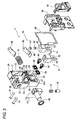
- the switch 11 includes: a main body 21 (See Fig. 3 ) with an opening on the front side; and a cover 46 to cover the main body 21.
- a switch assembly 50 to be described later is accommodated in the interior space of the main body 21.
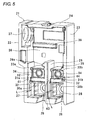
- the main body 21 includes a front frame 22, a rear frame 23, and an upper frame 24 which is installed above the front frame 22 and the rear frame 23.
- a standing wall 26 is formed to extend upward from a center portion of a lower end of the main body 21, and a first protrusion 26a is formed to protrude from the upper end of the standing wall 26 toward the side frame 22.
- a first accommodation space 27 is provided between the standing wall 26 and the front frame 22, and a second accommodation space 28 is provided between the standing wall 26 and the rear frame 23.
- Conductor insertion openings 29 and 29 that are openings through which conductors are externally inserted are provided at lower ends of the first accommodation space 27 and the second accommodation space 28, respectively.
- the top of the first accommodation space 27 is partitioned by a first partition wall 30a which extends horizontally from a middle portion of the standing wall 26 to the front frame 22.
- the top of the second accommodation space 28 is partitioned by a second partition wall 30b which extends horizontally from a lower portion of the rear frame 23 to the standing wall 26.
- grease guide grooves 32 are formed along the side end surfaces of the partition walls 30a and 30b.
- the partition walls 30a and 30b are located deep inside by a dimension L with respect to the side end surfaces of the front frame 22 and the standing wall 26 which are flush with each other.
- the dimension L is preferably short.
- a first barrier wall 31 a that horizontally extends from the standing wall 26 toward the front frame 22 is provided on the first partition wall 30a.
- a second barrier wall 31 b that horizontally extends from the standing wall 26 toward the rear frame 23 is provided on the second partition wall 30b.
- a first reinforcement portion 33a which is configured in a substantially rectangular parallelepiped shape and which is formed to stand from an interior surface of the main body 21 is provided on the top of the first barrier wall 31 a, and, similarly, a second reinforcement part 33b is provided on the top of the second barrier wall 31 b.
- through-holes 34 and 34 that extend through the main body 21 are respectively installed.
- a second protrusion 35 that protrudes from the rear frame 23 toward the standing wall 26 is formed in an upper base portion of the second reinforcement portion 33b.
- Predetermined gaps are provided between the first reinforcement portion 33a and the front frame 22 (opposite wall) which is opposite the first reinforcement portion 33a and between the second reinforcement part 33b and the standing wall 26 (opposite wall) which is opposite this second reinforcement part 33b.
- the predetermined gaps form a first reinforcement portion-side passage 42 and a second reinforcement portion-side passage 44, respectively.
- the third accommodation space 36 which is partitioned by the front frame 22, the rear frame 23, and the upper frame 24 and which has a larger volume than the first accommodation space 27 and the accommodation space 28 is formed above the first and second reinforcement portions 33a and 33b.
- the third accommodation space 36 communicates with the outside through a round hole 37 formed in an upper portion of the front frame 22, and an operation shaft 77 of a contact actuating member 71 to be described later passes through the round hole 37.
- An annular dustproof ring 38 is arranged around the round hole 37 to seal a clearance between the round hole 37 and the operation shaft 77.
- An engagement rib 39 which horizontally extends, protrudes inward from the interior surface in the third accommodation space 36, and a guide 72 of the contact actuating member 71 to be described later engages with the engagement rib 39.
- first accommodation space 27 communicates with the third accommodation space 36 through the first passage 41 and the first reinforcement portion-side passage 42.
- second accommodation space 28 communicates with the third accommodation space 36 through the second passage 43 and the second reinforcement portion-side passage 44.
- the front side of the cover 46 is shaped to cover the main body 21 and the cover 46 is locked to the main body 21 with a frame-shaped gasket 48 interposed therebetween by a pair of pins 47 that is inserted through the through-holes 34 of the main body 21.
- a motor splicer 49 that connects a power supply line to a motor is attached to the front surface of the cover 46.
- the switch assembly 50 includes a common terminal 51 and a fixed contact terminal 61 which are connected to an external circuit with a conductor such as a lead wire or a terminal which is not illustrated interposed therebetween, a movable contact piece 65 which is turnably supported on the common terminal 51 and the fixed contact terminal 61, and the contact actuating member 71 which is accommodated in the main body 21 in a slidable manner with a return spring 70 interposed therebetween.
- the movable contact piece 65 turns between a non-conduction position where the common terminal 51 and the fixed contact terminal 61 are not connected to each other and a conduction position where both of them are connected to each other.
- the contact actuating member 71 allows a movable contact piece 65 to turn from the non-conduction position to the conduction position by pressing force applied by the user, resisting against elastic force of the return spring 70.
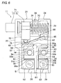
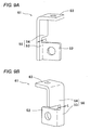
- the common terminal 51 includes a rectangular external-side connection portion 52 to be connected with a conductor such as a lead wire or a terminal, a blocking portion 56 which is bent at a right angle with respect to the external-side connection portion 52, and a turn support portion 58 which is a bent portion and is bent at a right angle from an upper end of the blocking portion 56 and then extends in a horizontal direction.
- the blocking portion 56 includes a prop 53 extending in a vertical direction and having a width dimension L, and a plate-shaped portion 54 extending upward from the prop 53 and having a large width.
- the width dimension L of the prop 53 is preferably short and it is equal to a depth dimension L of each of the first and second partition walls 30a and 30b.
- the turn support portion 58 includes a concave portion 57 which supports the turn center of the movable contact piece 65.
- the common terminal 51 mounted in the main body 21 is connected with a conductor such as a lead wire or a terminal (not shown) passing through the conductor insertion hole 29 and the external-side connection portion 52 of the common terminal 51 is accommodated in the first accommodation space 27 of the main body 21.
- the lead wire is pinched between the external-side connection portion 52 and a rectangular washer 59 accommodated in the first accommodation space 27, and it is fixed by a screw 60.
- the blocking portion 56 is fitted in the first passage 41 and the first reinforcement portion-side passage 42 of the main body 21.
- the turn support portion 58 is accommodated in a lower portion of the third accommodation space 36 and is locked to the first protrusion 26a of the standing wall 26.
- the fixed contact terminal 61 includes an external-side connection portion 52, a blocking portion 56, and a horizontal plane portion 63 that is a bent portion which is folded and bent from an upper portion of the blocking portion 56 at a right angle, then extends horizontally, and is provided with a fixed contact 62 (See Fig. 3 ) which is brought into contact with or is separated from the movable contact piece 65.
- the fixed contact terminal 61 mounted in the main body 21 is connected with a conductor such as a lead wire or a terminal through a conductor insertion hole 29 and the external-side connection portion 52 of the fixed contact terminal 61 is accommodated in the second accommodation space 28 of the main body 21.
- the lead wire is pinched between the external-side connection portion 52 and the rectangular washer 59 accommodated in the second accommodation space 28, and it is fixed by a screw 60.
- the blocking portion 56 is fitted in the second passage 43 and the second reinforcement portion-side passage 44 of the main body 21.
- the horizontal plane portion 63 is accommodated in a lower portion of the third accommodation space 36 and is locked to the second protrusion 35 of the rear frame 23.
- the movable contact piece 65 has a long-plate shape as illustrated in Fig. 3 and includes a turning portion 66 serving as the turn center between the non-conduction position and the conduction position, in which the turning portion 66 is formed to protrude downward in the vicinity of an end of the movable contact piece 65.
- a movable contact 67 is attached to the other end of the movable contact piece 65 in a manner of being brought into contact with the fixed contact 62.
- a slide contact plate 68 which is substantially the same in shape as the movable contact piece 65 is attached to the top surface of the movable contact piece 65, and the movable contact piece 65 and the contact actuating member 71 are slidably in contact with each other with the slide contact plate 68 interposed therebetween.
- the movable contact piece 65 mounted in the main body 21 is disposed on top of the common terminal 51 and the fixed contact terminal 61 in the third accommodation space 36, and the turning portion 66 thereof engages with the concave portion 57 of the common terminal 51 to be turnably supported.
- the contact actuating member 71 includes a rectangular parallelepiped guide 72 extending in the vertical direction, and a cylindrical operation shaft 77 that horizontally extends from the guide 72.
- a hollow portion 73 with a circular cross section is formed to extend upward from the bottom surface.
- a pressing portion 75 with a conical leading end protruding from the bottom surface is fitted in the hollow portion 73 with the spring 74 interposed therebetween.
- the contact actuating member 71 mounted in the main body 21 is accommodated in the third accommodation space 36 so that the guide 72 engages with the engagement rib 39. Moreover, the contact actuating member 71 is biased toward the front frame 22 by the return spring 70 installed between the rear frame 23 and the contact actuating member 71 and thus the operation shaft 77 is driven through the round hole 37 of the main body 21 so as to protrude outside.
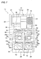
- the washer 59 provided with a female screw is put inside the first and second accommodation spaces 27 and 28. Then, the external-side connection portion 52 of the common terminal 51 is fitted in the first accommodation space 27, and the plate-shaped portion 54 is fitted in each of the first passage 41 and the first reinforcement portion-side passage 42. At this time, since the prop 53 of the common terminal 51 is locked to the edge of the first partition wall 30a and the plate-shaped portion 54 blocks up the first passage 41, entry of dust from the conductor insertion hole 29 is prevented and as a result an enough dustproof performance can be maintained.
- the plate-shaped portion 54 blocks up the first reinforcement portion-side passage 42, entry of dust is prevented at two places, that is, at the first passage 41 and the first reinforcement portion-side passage 42. Accordingly, a dustproof performance can be further improved.
- a leading end of the turn support portion 58 located at the bottom of the third accommodation space 36 is locked to the first protrusion 26a. As a result, dust that has entered from the conductor insertion hole 29 can be blocked by the turn support portion 58 and the first protrusion 26a, so the dust is inhibited from arriving at the movable contact piece 65. That is, a dustproof performance can be further improved.
- the external-side connection portion 52 is fitted in the second accommodation space 28, and the plate-shaped portion 54 is fitted in the second passage 43 and the second reinforcement portion-side passage 44. With this configuration, a leading end of the horizontal plane portion 63 located in a lower portion of the third accommodation space 36 is locked to the second protrusion 35.
- the movable contact piece 65 is disposed above the common terminal 51 and the fixed contact terminal 61 in the third accommodation space 36 so that the turning portion 66 of the movable contact piece 65 can engage with the concave portion 57 of the common terminal 51.
- the guide 72 is installed between the movable contact piece 65 and the upper frame 24 and the operation shaft 77 is driven through the round hole 37 to protrude outside so that the pressing portion 75 of the guide 72 pushes an end of the movable contact piece 65 with the slide contact plate 68 interposed therebetween.
- the return spring 70 is installed between the guide 72 and the rear frame 23 so that the guide 72 can be biased toward the front frame 22 by the spring force of the return spring 70.
- the manufacturing cost can be reduced, and deterioration of the dustproof performance due to deterioration of the grease with time can be prevented by relatively a lot compared to conventional examples.
- the grease may be further spread between the first reinforcement portion 33a and the common terminal 51 and between the second reinforcement portion 33b and the fixed contact terminal 61.
- the first reinforcement portion-side passage 42 and the second reinforcement portion-side passage 44 can be sealed, so that a dustproof performance can be further improved.
- the cover 46 is locked to the main body 21 by the pin 47 with the frame gasket 48 interposed therebetween, the pin 47 being inserted in the through-hole 34 of the main body 21.
- the motor splicer 49 is mounted on the front surface of the cover 46.
- Conductors such as lead wires or terminals are inserted between the external-side connection portions 52 of the common terminal 51 and the fixed contact terminal 61 and the washer 59, and moreover, the screw 60 is screwed to make connection.
- the guide 72 When the user releases the pressing force applied to the operation shaft 77, the guide 72 is pushed to be returned by the spring force of the return spring 70 and is then moved toward the front frame 22 while being in contact with and sliding on the upper frame 24 and the engagement rib 39. Then, the pressing portion 75 pushes the edge of the sliding contact plate 68 on the side of the turning portion 66 and the movable contact piece 65 is kept at the non-conduction position in a state in which the guide 72 is stopped by being brought into contact with the front frame 22.
- the inventors of the present application performed comparison experiments to compare the dustproof between the switch 11 according to the present invention and conventional goods.
- grease was spread between the common terminal 51 and the guide groove 32 of the first partition wall 30a and between the fixed contact terminal 61 and the guide groove 32 of the second partition wall 30b in the switch 11 illustrated in Fig. 6 .
- grease was spread on the entire side end surface of the wall portion surrounding the space corresponding to the first accommodation space and the second accommodation space.
- the amount of the grease spread in the comparative example was about ten times that of the embodiment.
- the switches were turned on and off 1000 times in sealed atmosphere filled with a concrete powder of 150 micrometers.
Landscapes
- Push-Button Switches (AREA)
- Switch Cases, Indication, And Locking (AREA)
- Connector Housings Or Holding Contact Members (AREA)
Claims (4)
- Schalter, aufweisend:eine Mehrzahl an einem Hauptkörper (21) befestigter Terminale (51, 61); ein bewegliches Kontaktstück (65), welches derart an dem Hauptkörper (21) gestützt ist, dass es zwischen einer nicht-leitenden Lage, in welcher die Terminale (51, 61) nicht miteinander verbunden sind, und einer leitenden Lage, in welcher die Terminale (51, 61) miteinander verbunden sind, versetzt wird; undein Kontaktsteuerelement (71), welches in dem Hauptkörper (21) aufgenommen ist und welches das bewegliche Kontaktstück (65) aus der nicht-leitenden Lage durch Anwendung einer äußeren Druckkraft in die leitende Lage versetzt, wobeider Hauptkörper (21) eine Öffnung (29) aufweist, welche mit der Außenseite in Verbindung steht, eine Barrierewand (31 a, 31 b) und eine Passage (41, 43), welche durch einen Endabschnitt der Barrierewand (31 a, 31 b) und eine gegenüberliegende Wand (22, 26), die dem Endabschnitt der Barrierewand gegenüber liegt, gebildet ist,wobei das Terminal (51, 61) einen Verbindungsabschnitt (52) aufweist, der mit einem durch die Öffnung verlaufenden Leiter verbunden ist,dadurch gekennzeichnet, dass
der Hauptkörper außerdem eine Trennwand (30a, 30b) aufweist, die zwischen der Öffnung (29) und dem beweglichen Kontaktstück ausgebildet ist,
die Barrierewand über der Trennwand ausgebildet ist,
die Trennwand (30a, 30b) die Passage kreuzt und
das Terminal weiterhin einen Blockierabschnitt (56) aufweist, welcher von dem Verbindungsabschnitt (52) aus gebogen ist und die Passage (41, 43) blockiert. - Schalter nach Anspruch 1, wobei die Trennwand (30a, 30b) eine Führungsnut aufweist, welche eingesetzt ist, um ein viskoses Material zwischen der Trennwand (30a, 30b) und den Terminalen (51, 61) auszubreiten.
- Schalter nach Anspruch 1 oder 2, weiterhin aufweisend:eine Abdeckung (46), die den Hauptkörper (21) bedeckt, wobei der Hauptkörper (21) weiterhin einen Verstärkungsabschnitt (33a, 33b) aufweist, welcher die Abdeckung (46) zwischen der Barrierewand (31 a, 31 b) und dem beweglichen Kontaktstück (65) fixiert, und eine verstärkungsabschnittsseitige Passage (42, 44), welche durch den Verstärkungsabschnitt (33a, 33b) und die gegenüberliegende Wand (22, 26) gebildet ist, welche dem Verstärkungsabschnitt gegenüber liegt, und der Blockierabschnitt (56) des Terminals (51, 61) die verstärkungsabschnittsseitige Passage (42, 44) blockiert.
- Schalter nach einem der Ansprüche 1 bis 3, wobei der Hauptkörper (21) einen Vorsprung (26a, 35) aufweist, welcher zwischen der Barrierewand und dem beweglichen Kontaktstück vorgesehen ist, wobei das Terminal (51, 61) einen gebogenen Abschnitt (58, 63) aufweist, welcher von dem Blockierabschnitt (56) auf der gegenüberliegenden Seite des Verbindungsabschnitts des Terminals aus gebogen ist, und der gebogene Abschnitt an den Vorsprung geschlossen ist.
Applications Claiming Priority (1)
| Application Number | Priority Date | Filing Date | Title |
|---|---|---|---|
| JP2011176919A JP5811678B2 (ja) | 2011-08-12 | 2011-08-12 | スイッチ |
Publications (2)
| Publication Number | Publication Date |
|---|---|
| EP2557580A1 EP2557580A1 (de) | 2013-02-13 |
| EP2557580B1 true EP2557580B1 (de) | 2013-12-11 |
Family
ID=46507835
Family Applications (1)
| Application Number | Title | Priority Date | Filing Date |
|---|---|---|---|
| EP12004725.3A Active EP2557580B1 (de) | 2011-08-12 | 2012-06-22 | Schalter |
Country Status (4)
| Country | Link |
|---|---|
| US (1) | US8809712B2 (de) |
| EP (1) | EP2557580B1 (de) |
| JP (1) | JP5811678B2 (de) |
| CN (1) | CN102956385B (de) |
Families Citing this family (6)
| Publication number | Priority date | Publication date | Assignee | Title |
|---|---|---|---|---|
| JP6160303B2 (ja) * | 2013-06-27 | 2017-07-12 | オムロン株式会社 | スイッチユニット |
| DE102016117786A1 (de) * | 2016-09-21 | 2018-03-22 | Johnson Electric Germany GmbH & Co. KG | Elektrischer Schalter |
| JP6690525B2 (ja) * | 2016-12-28 | 2020-04-28 | オムロン株式会社 | スイッチの接点構造、トリガースイッチ及び電動工具 |
| JP6720901B2 (ja) * | 2017-03-14 | 2020-07-08 | オムロン株式会社 | トリガースイッチ |
| JP7631916B2 (ja) * | 2021-03-10 | 2025-02-19 | オムロン株式会社 | スイッチ |
| US11363727B1 (en) * | 2021-04-30 | 2022-06-14 | Suprema Inc. | Terminal apparatus and terminal equipment including the same |
Family Cites Families (20)
| Publication number | Priority date | Publication date | Assignee | Title |
|---|---|---|---|---|
| US3268700A (en) * | 1964-06-18 | 1966-08-23 | Illinois Tool Works | Snap acting trigger switch |
| US3652811A (en) * | 1970-08-17 | 1972-03-28 | Ark Les Switch Corp | Laminated locking slider multiple circuit pushbutton switch assembly with improved connectors for plug-in wires |
| JPS55155424A (en) * | 1979-05-24 | 1980-12-03 | Omron Tateisi Electronics Co | Dip switch |
| JPS60109222U (ja) * | 1983-12-26 | 1985-07-24 | 株式会社山武 | スナツプスイツチの端子板取付け装置 |
| JPS60138221U (ja) * | 1984-02-24 | 1985-09-12 | オムロン株式会社 | 端子の取付け構造 |
| JPS62176925U (de) * | 1986-04-30 | 1987-11-10 | ||
| US4839483A (en) * | 1986-10-22 | 1989-06-13 | Conair Corporation | Modular watertight switch for use in personal care appliances |
| DE3882007T2 (de) * | 1987-10-21 | 1994-02-17 | Omron Tateisi Electronics Co | Elektrischer Schalter für Elektrowerkzeug. |
| US5343008A (en) * | 1992-02-19 | 1994-08-30 | Ipcinski Ralph G | Sealed switch |
| JP3240670B2 (ja) * | 1992-02-24 | 2001-12-17 | オムロン株式会社 | 電気機器の端子シール構造 |
| JP2951152B2 (ja) * | 1993-06-15 | 1999-09-20 | アルプス電気株式会社 | スイッチ装置 |
| US5862029A (en) * | 1998-04-16 | 1999-01-19 | Conair Corporation | Resettable immersion detecting circuit interrupter (IDCI) |
| JP2005093347A (ja) | 2003-09-19 | 2005-04-07 | Alps Electric Co Ltd | 押釦スイッチ |
| JP2006218560A (ja) * | 2005-02-09 | 2006-08-24 | Satori S-Tech Co Ltd | トリガースイッチ |
| EP1691385B1 (de) * | 2005-02-09 | 2010-05-05 | Satori S-Tech Co., Ltd. | Triggerschalter |
| US7289306B2 (en) * | 2005-02-25 | 2007-10-30 | Huadao Huang | Ground fault circuit interrupter containing a dual-function test button |
| US7211758B2 (en) * | 2005-07-12 | 2007-05-01 | Defond Components Limited | Circuit interrupter that produces snap-action connection and disconnection between electrical contacts |
| EP1836945A2 (de) * | 2006-03-20 | 2007-09-26 | Olympus Medical Systems Corp. | Schaltmechanismus zur Verwendung bei medizinischen Geräten und Bildaufnahmevorrichtung zur Verwendung bei Endoskopen |
| JP4941048B2 (ja) * | 2007-03-28 | 2012-05-30 | オムロン株式会社 | トリガスイッチ |
| JP2009199981A (ja) * | 2008-02-25 | 2009-09-03 | Satori S-Tech Co Ltd | 電動工具用スイッチ |
-
2011
- 2011-08-12 JP JP2011176919A patent/JP5811678B2/ja active Active
-
2012
- 2012-06-21 CN CN201210211408.4A patent/CN102956385B/zh active Active
- 2012-06-22 US US13/530,215 patent/US8809712B2/en active Active
- 2012-06-22 EP EP12004725.3A patent/EP2557580B1/de active Active
Also Published As
| Publication number | Publication date |
|---|---|
| JP2013041715A (ja) | 2013-02-28 |
| CN102956385A (zh) | 2013-03-06 |
| CN102956385B (zh) | 2015-02-11 |
| EP2557580A1 (de) | 2013-02-13 |
| JP5811678B2 (ja) | 2015-11-11 |
| US8809712B2 (en) | 2014-08-19 |
| US20130037398A1 (en) | 2013-02-14 |
Similar Documents
| Publication | Publication Date | Title |
|---|---|---|
| EP2557580B1 (de) | Schalter | |
| EP3916926B1 (de) | Hochspannungsfingerschutz | |
| US9490081B2 (en) | Limit switch | |
| CN101409406B (zh) | 连接器的连接结构 | |
| EP2889890B1 (de) | Elektronische komponentenanordnung, verbindungsstruktur für eine elektronische komponentenanordnung und elektrischer anschlusskasten mit einer elektronischen komponentenanordnung | |
| US10136539B2 (en) | Electronic component assembly structure and electronic component | |
| JP2011524614A (ja) | アダプタ・プラグ | |
| US9236679B2 (en) | Electric coupling element | |
| JP6138560B2 (ja) | 電子部品の組付構造及び電気接続箱 | |
| US9984842B2 (en) | Electronic component assembly structure and electronic component | |
| JP2016040974A (ja) | リーク遮断構造、電子部品、及び、電子部品ユニット | |
| US20020097551A1 (en) | Drawing apparatus for a drawer type electrical machinery | |
| RU2572394C2 (ru) | Электрическая розетка, содержащая вертикальные стойки, выполненные с возможностью поступательного перемещения | |
| US20170141503A1 (en) | Stop Spring For A Contact Device, Electrical Contact De-vice Assembly as Well as Electrical Connector | |
| US10128605B2 (en) | Connector | |
| KR20000017090A (ko) | 커넥터의 하우징 및 그것에 의해 제조된 커넥터 | |
| US20150064988A1 (en) | Connector | |
| EP3291268B1 (de) | Schaltvorrichtung | |
| WO2014053424A1 (en) | Connector and construction kit for a connector | |
| US9818558B2 (en) | Snap action switch | |
| EP2685483B1 (de) | Schalter | |
| KR102177144B1 (ko) | 트리거 스위치 | |
| HK1253840A1 (en) | Program switch and modular arrangement for mounting on a printed circuit board and producing method therefor | |
| US6172310B1 (en) | Switching device for an electrical connector | |
| KR20160000683A (ko) | 헤더 어셈블리 및 이를 구비하는 차량용 커넥터 장치 |
Legal Events
| Date | Code | Title | Description |
|---|---|---|---|
| PUAI | Public reference made under article 153(3) epc to a published international application that has entered the european phase |
Free format text: ORIGINAL CODE: 0009012 |
|
| AK | Designated contracting states |
Kind code of ref document: A1 Designated state(s): AL AT BE BG CH CY CZ DE DK EE ES FI FR GB GR HR HU IE IS IT LI LT LU LV MC MK MT NL NO PL PT RO RS SE SI SK SM TR |
|
| AX | Request for extension of the european patent |
Extension state: BA ME |
|
| GRAP | Despatch of communication of intention to grant a patent |
Free format text: ORIGINAL CODE: EPIDOSNIGR1 |
|
| 17P | Request for examination filed |
Effective date: 20130521 |
|
| RIC1 | Information provided on ipc code assigned before grant |
Ipc: H01H 9/04 20060101AFI20130604BHEP Ipc: H01H 9/06 20060101ALI20130604BHEP |
|
| INTG | Intention to grant announced |
Effective date: 20130621 |
|
| GRAS | Grant fee paid |
Free format text: ORIGINAL CODE: EPIDOSNIGR3 |
|
| GRAA | (expected) grant |
Free format text: ORIGINAL CODE: 0009210 |
|
| AK | Designated contracting states |
Kind code of ref document: B1 Designated state(s): AL AT BE BG CH CY CZ DE DK EE ES FI FR GB GR HR HU IE IS IT LI LT LU LV MC MK MT NL NO PL PT RO RS SE SI SK SM TR |
|
| REG | Reference to a national code |
Ref country code: GB Ref legal event code: FG4D |
|
| REG | Reference to a national code |
Ref country code: CH Ref legal event code: EP |
|
| REG | Reference to a national code |
Ref country code: AT Ref legal event code: REF Ref document number: 644954 Country of ref document: AT Kind code of ref document: T Effective date: 20140115 |
|
| REG | Reference to a national code |
Ref country code: IE Ref legal event code: FG4D |
|
| REG | Reference to a national code |
Ref country code: DE Ref legal event code: R096 Ref document number: 602012000621 Country of ref document: DE Effective date: 20140213 |
|
| REG | Reference to a national code |
Ref country code: NL Ref legal event code: VDEP Effective date: 20131211 |
|
| REG | Reference to a national code |
Ref country code: AT Ref legal event code: MK05 Ref document number: 644954 Country of ref document: AT Kind code of ref document: T Effective date: 20131211 |
|
| PG25 | Lapsed in a contracting state [announced via postgrant information from national office to epo] |
Ref country code: NL Free format text: LAPSE BECAUSE OF FAILURE TO SUBMIT A TRANSLATION OF THE DESCRIPTION OR TO PAY THE FEE WITHIN THE PRESCRIBED TIME-LIMIT Effective date: 20131211 Ref country code: SE Free format text: LAPSE BECAUSE OF FAILURE TO SUBMIT A TRANSLATION OF THE DESCRIPTION OR TO PAY THE FEE WITHIN THE PRESCRIBED TIME-LIMIT Effective date: 20131211 Ref country code: LT Free format text: LAPSE BECAUSE OF FAILURE TO SUBMIT A TRANSLATION OF THE DESCRIPTION OR TO PAY THE FEE WITHIN THE PRESCRIBED TIME-LIMIT Effective date: 20131211 Ref country code: HR Free format text: LAPSE BECAUSE OF FAILURE TO SUBMIT A TRANSLATION OF THE DESCRIPTION OR TO PAY THE FEE WITHIN THE PRESCRIBED TIME-LIMIT Effective date: 20131211 Ref country code: FI Free format text: LAPSE BECAUSE OF FAILURE TO SUBMIT A TRANSLATION OF THE DESCRIPTION OR TO PAY THE FEE WITHIN THE PRESCRIBED TIME-LIMIT Effective date: 20131211 Ref country code: NO Free format text: LAPSE BECAUSE OF FAILURE TO SUBMIT A TRANSLATION OF THE DESCRIPTION OR TO PAY THE FEE WITHIN THE PRESCRIBED TIME-LIMIT Effective date: 20140311 |
|
| REG | Reference to a national code |
Ref country code: LT Ref legal event code: MG4D |
|
| PG25 | Lapsed in a contracting state [announced via postgrant information from national office to epo] |
Ref country code: CY Free format text: LAPSE BECAUSE OF FAILURE TO SUBMIT A TRANSLATION OF THE DESCRIPTION OR TO PAY THE FEE WITHIN THE PRESCRIBED TIME-LIMIT Effective date: 20131211 Ref country code: LV Free format text: LAPSE BECAUSE OF FAILURE TO SUBMIT A TRANSLATION OF THE DESCRIPTION OR TO PAY THE FEE WITHIN THE PRESCRIBED TIME-LIMIT Effective date: 20131211 Ref country code: RS Free format text: LAPSE BECAUSE OF FAILURE TO SUBMIT A TRANSLATION OF THE DESCRIPTION OR TO PAY THE FEE WITHIN THE PRESCRIBED TIME-LIMIT Effective date: 20131211 Ref country code: AT Free format text: LAPSE BECAUSE OF FAILURE TO SUBMIT A TRANSLATION OF THE DESCRIPTION OR TO PAY THE FEE WITHIN THE PRESCRIBED TIME-LIMIT Effective date: 20131211 |
|
| PG25 | Lapsed in a contracting state [announced via postgrant information from national office to epo] |
Ref country code: IS Free format text: LAPSE BECAUSE OF FAILURE TO SUBMIT A TRANSLATION OF THE DESCRIPTION OR TO PAY THE FEE WITHIN THE PRESCRIBED TIME-LIMIT Effective date: 20140411 Ref country code: BE Free format text: LAPSE BECAUSE OF FAILURE TO SUBMIT A TRANSLATION OF THE DESCRIPTION OR TO PAY THE FEE WITHIN THE PRESCRIBED TIME-LIMIT Effective date: 20131211 Ref country code: EE Free format text: LAPSE BECAUSE OF FAILURE TO SUBMIT A TRANSLATION OF THE DESCRIPTION OR TO PAY THE FEE WITHIN THE PRESCRIBED TIME-LIMIT Effective date: 20131211 |
|
| PG25 | Lapsed in a contracting state [announced via postgrant information from national office to epo] |
Ref country code: ES Free format text: LAPSE BECAUSE OF FAILURE TO SUBMIT A TRANSLATION OF THE DESCRIPTION OR TO PAY THE FEE WITHIN THE PRESCRIBED TIME-LIMIT Effective date: 20131211 Ref country code: PL Free format text: LAPSE BECAUSE OF FAILURE TO SUBMIT A TRANSLATION OF THE DESCRIPTION OR TO PAY THE FEE WITHIN THE PRESCRIBED TIME-LIMIT Effective date: 20131211 Ref country code: RO Free format text: LAPSE BECAUSE OF FAILURE TO SUBMIT A TRANSLATION OF THE DESCRIPTION OR TO PAY THE FEE WITHIN THE PRESCRIBED TIME-LIMIT Effective date: 20131211 Ref country code: PT Free format text: LAPSE BECAUSE OF FAILURE TO SUBMIT A TRANSLATION OF THE DESCRIPTION OR TO PAY THE FEE WITHIN THE PRESCRIBED TIME-LIMIT Effective date: 20140411 Ref country code: CZ Free format text: LAPSE BECAUSE OF FAILURE TO SUBMIT A TRANSLATION OF THE DESCRIPTION OR TO PAY THE FEE WITHIN THE PRESCRIBED TIME-LIMIT Effective date: 20131211 Ref country code: SK Free format text: LAPSE BECAUSE OF FAILURE TO SUBMIT A TRANSLATION OF THE DESCRIPTION OR TO PAY THE FEE WITHIN THE PRESCRIBED TIME-LIMIT Effective date: 20131211 |
|
| REG | Reference to a national code |
Ref country code: DE Ref legal event code: R097 Ref document number: 602012000621 Country of ref document: DE |
|
| PLBE | No opposition filed within time limit |
Free format text: ORIGINAL CODE: 0009261 |
|
| STAA | Information on the status of an ep patent application or granted ep patent |
Free format text: STATUS: NO OPPOSITION FILED WITHIN TIME LIMIT |
|
| PG25 | Lapsed in a contracting state [announced via postgrant information from national office to epo] |
Ref country code: DK Free format text: LAPSE BECAUSE OF FAILURE TO SUBMIT A TRANSLATION OF THE DESCRIPTION OR TO PAY THE FEE WITHIN THE PRESCRIBED TIME-LIMIT Effective date: 20131211 |
|
| 26N | No opposition filed |
Effective date: 20140912 |
|
| REG | Reference to a national code |
Ref country code: DE Ref legal event code: R097 Ref document number: 602012000621 Country of ref document: DE Effective date: 20140912 |
|
| PG25 | Lapsed in a contracting state [announced via postgrant information from national office to epo] |
Ref country code: MC Free format text: LAPSE BECAUSE OF FAILURE TO SUBMIT A TRANSLATION OF THE DESCRIPTION OR TO PAY THE FEE WITHIN THE PRESCRIBED TIME-LIMIT Effective date: 20131211 Ref country code: LU Free format text: LAPSE BECAUSE OF FAILURE TO SUBMIT A TRANSLATION OF THE DESCRIPTION OR TO PAY THE FEE WITHIN THE PRESCRIBED TIME-LIMIT Effective date: 20140622 |
|
| PG25 | Lapsed in a contracting state [announced via postgrant information from national office to epo] |
Ref country code: SI Free format text: LAPSE BECAUSE OF FAILURE TO SUBMIT A TRANSLATION OF THE DESCRIPTION OR TO PAY THE FEE WITHIN THE PRESCRIBED TIME-LIMIT Effective date: 20131211 |
|
| REG | Reference to a national code |
Ref country code: IE Ref legal event code: MM4A |
|
| REG | Reference to a national code |
Ref country code: FR Ref legal event code: ST Effective date: 20150227 |
|
| REG | Reference to a national code |
Ref country code: DE Ref legal event code: R082 Ref document number: 602012000621 Country of ref document: DE Representative=s name: ISARPATENT PATENTANWAELTE BEHNISCH, BARTH, CHA, DE Ref country code: DE Ref legal event code: R082 Ref document number: 602012000621 Country of ref document: DE Representative=s name: ISARPATENT - PATENTANWAELTE- UND RECHTSANWAELT, DE |
|
| PG25 | Lapsed in a contracting state [announced via postgrant information from national office to epo] |
Ref country code: IE Free format text: LAPSE BECAUSE OF NON-PAYMENT OF DUE FEES Effective date: 20140622 |
|
| PG25 | Lapsed in a contracting state [announced via postgrant information from national office to epo] |
Ref country code: FR Free format text: LAPSE BECAUSE OF NON-PAYMENT OF DUE FEES Effective date: 20140630 |
|
| REG | Reference to a national code |
Ref country code: CH Ref legal event code: PL |
|
| PG25 | Lapsed in a contracting state [announced via postgrant information from national office to epo] |
Ref country code: MT Free format text: LAPSE BECAUSE OF FAILURE TO SUBMIT A TRANSLATION OF THE DESCRIPTION OR TO PAY THE FEE WITHIN THE PRESCRIBED TIME-LIMIT Effective date: 20131211 |
|
| PG25 | Lapsed in a contracting state [announced via postgrant information from national office to epo] |
Ref country code: LI Free format text: LAPSE BECAUSE OF NON-PAYMENT OF DUE FEES Effective date: 20150630 Ref country code: CH Free format text: LAPSE BECAUSE OF NON-PAYMENT OF DUE FEES Effective date: 20150630 Ref country code: SM Free format text: LAPSE BECAUSE OF FAILURE TO SUBMIT A TRANSLATION OF THE DESCRIPTION OR TO PAY THE FEE WITHIN THE PRESCRIBED TIME-LIMIT Effective date: 20131211 |
|
| PG25 | Lapsed in a contracting state [announced via postgrant information from national office to epo] |
Ref country code: IT Free format text: LAPSE BECAUSE OF FAILURE TO SUBMIT A TRANSLATION OF THE DESCRIPTION OR TO PAY THE FEE WITHIN THE PRESCRIBED TIME-LIMIT Effective date: 20131211 Ref country code: BG Free format text: LAPSE BECAUSE OF FAILURE TO SUBMIT A TRANSLATION OF THE DESCRIPTION OR TO PAY THE FEE WITHIN THE PRESCRIBED TIME-LIMIT Effective date: 20131211 Ref country code: GR Free format text: LAPSE BECAUSE OF FAILURE TO SUBMIT A TRANSLATION OF THE DESCRIPTION OR TO PAY THE FEE WITHIN THE PRESCRIBED TIME-LIMIT Effective date: 20140312 |
|
| PG25 | Lapsed in a contracting state [announced via postgrant information from national office to epo] |
Ref country code: TR Free format text: LAPSE BECAUSE OF FAILURE TO SUBMIT A TRANSLATION OF THE DESCRIPTION OR TO PAY THE FEE WITHIN THE PRESCRIBED TIME-LIMIT Effective date: 20131211 Ref country code: HU Free format text: LAPSE BECAUSE OF FAILURE TO SUBMIT A TRANSLATION OF THE DESCRIPTION OR TO PAY THE FEE WITHIN THE PRESCRIBED TIME-LIMIT; INVALID AB INITIO Effective date: 20120622 |
|
| PG25 | Lapsed in a contracting state [announced via postgrant information from national office to epo] |
Ref country code: MK Free format text: LAPSE BECAUSE OF FAILURE TO SUBMIT A TRANSLATION OF THE DESCRIPTION OR TO PAY THE FEE WITHIN THE PRESCRIBED TIME-LIMIT Effective date: 20131211 |
|
| PG25 | Lapsed in a contracting state [announced via postgrant information from national office to epo] |
Ref country code: AL Free format text: LAPSE BECAUSE OF FAILURE TO SUBMIT A TRANSLATION OF THE DESCRIPTION OR TO PAY THE FEE WITHIN THE PRESCRIBED TIME-LIMIT Effective date: 20131211 |
|
| PGFP | Annual fee paid to national office [announced via postgrant information from national office to epo] |
Ref country code: DE Payment date: 20250618 Year of fee payment: 14 |
|
| PGFP | Annual fee paid to national office [announced via postgrant information from national office to epo] |
Ref country code: GB Payment date: 20250620 Year of fee payment: 14 |