EP2557621A1 - Brennstoffzelle - Google Patents
Brennstoffzelle Download PDFInfo
- Publication number
- EP2557621A1 EP2557621A1 EP11177122A EP11177122A EP2557621A1 EP 2557621 A1 EP2557621 A1 EP 2557621A1 EP 11177122 A EP11177122 A EP 11177122A EP 11177122 A EP11177122 A EP 11177122A EP 2557621 A1 EP2557621 A1 EP 2557621A1
- Authority
- EP
- European Patent Office
- Prior art keywords
- reactant gas
- flow channels
- fuel cell
- channels
- flow
- Prior art date
- Legal status (The legal status is an assumption and is not a legal conclusion. Google has not performed a legal analysis and makes no representation as to the accuracy of the status listed.)
- Withdrawn
Links
Images

Classifications
-
- H—ELECTRICITY
- H01—ELECTRIC ELEMENTS
- H01M—PROCESSES OR MEANS, e.g. BATTERIES, FOR THE DIRECT CONVERSION OF CHEMICAL ENERGY INTO ELECTRICAL ENERGY
- H01M8/00—Fuel cells; Manufacture thereof
- H01M8/02—Details
- H01M8/0202—Collectors; Separators, e.g. bipolar separators; Interconnectors
- H01M8/0258—Collectors; Separators, e.g. bipolar separators; Interconnectors characterised by the configuration of channels, e.g. by the flow field of the reactant or coolant
- H01M8/0265—Collectors; Separators, e.g. bipolar separators; Interconnectors characterised by the configuration of channels, e.g. by the flow field of the reactant or coolant the reactant or coolant channels having varying cross sections
-
- H—ELECTRICITY
- H01—ELECTRIC ELEMENTS
- H01M—PROCESSES OR MEANS, e.g. BATTERIES, FOR THE DIRECT CONVERSION OF CHEMICAL ENERGY INTO ELECTRICAL ENERGY
- H01M8/00—Fuel cells; Manufacture thereof
- H01M8/02—Details
- H01M8/0202—Collectors; Separators, e.g. bipolar separators; Interconnectors
- H01M8/0258—Collectors; Separators, e.g. bipolar separators; Interconnectors characterised by the configuration of channels, e.g. by the flow field of the reactant or coolant
- H01M8/026—Collectors; Separators, e.g. bipolar separators; Interconnectors characterised by the configuration of channels, e.g. by the flow field of the reactant or coolant characterised by grooves, e.g. their pitch or depth
-
- H—ELECTRICITY
- H01—ELECTRIC ELEMENTS
- H01M—PROCESSES OR MEANS, e.g. BATTERIES, FOR THE DIRECT CONVERSION OF CHEMICAL ENERGY INTO ELECTRICAL ENERGY
- H01M8/00—Fuel cells; Manufacture thereof
- H01M8/10—Fuel cells with solid electrolytes
- H01M2008/1095—Fuel cells with polymeric electrolytes
-
- Y—GENERAL TAGGING OF NEW TECHNOLOGICAL DEVELOPMENTS; GENERAL TAGGING OF CROSS-SECTIONAL TECHNOLOGIES SPANNING OVER SEVERAL SECTIONS OF THE IPC; TECHNICAL SUBJECTS COVERED BY FORMER USPC CROSS-REFERENCE ART COLLECTIONS [XRACs] AND DIGESTS
- Y02—TECHNOLOGIES OR APPLICATIONS FOR MITIGATION OR ADAPTATION AGAINST CLIMATE CHANGE
- Y02E—REDUCTION OF GREENHOUSE GAS [GHG] EMISSIONS, RELATED TO ENERGY GENERATION, TRANSMISSION OR DISTRIBUTION
- Y02E60/00—Enabling technologies; Technologies with a potential or indirect contribution to GHG emissions mitigation
- Y02E60/30—Hydrogen technology
- Y02E60/50—Fuel cells
Definitions
- the present invention relates to a fuel cell, in particular a proton exchange membrane fuel cell, for use in portable power sources, electric vehicle power sources, domestic cogeneration systems or the like.
- Hydrogen is a very attractive fuel because it is clean and can be used to efficiently produce electricity in a fuel cell.
- the automotive industry expends significant resources in the development of hydrogen fuel cells as a source of power for vehicles. Such vehicles would be more efficient and generate fewer emissions than today's vehicles employing internal combustion engines.
- a hydrogen fuel cell is an electrochemical device that includes an anode and a cathode with an electrolyte therebetween.
- the anode receives hydrogen gas and the cathode receives oxygen or air.
- the hydrogen gas is dissociated in the anode to generate free protons and electrons.
- the protons pass through the electrolyte to the cathode.
- the protons react with the oxygen and the electrons in the cathode to generate water.
- the electrons from the anode cannot pass through the electrolyte, and thus are directed through a load to perform work before being sent to the cathode.
- Proton exchange membrane (PEM) fuel cells are popular fuel cells for vehicles.
- the PEM fuel cell generally includes a solid polymer-electrolyte proton-conducting membrane, such as a perfluorosulfonic acid membrane.
- the anode and cathode typically include finely divided catalytic particles, usually platinum (Pt), supported on carbon particles and mixed with an ionomer.
- the catalytic mixture is deposited on opposing sides of the membrane.
- the combination of the anode catalytic mixture, the cathode catalytic mixture and the membrane define a membrane electrode assembly (MEA).
- MEAs are relatively expensive to manufacture and require certain conditions for effective operation.
- the stack may include about two hundred or more fuel cells.
- the fuel cell stack receives a cathode reactant gas, typically a flow of air forced through the stack by a compressor. Not all of the oxygen is consumed by the stack and some of the air is output as a cathode exhaust gas that may include water as a stack byproduct.
- the fuel cell stack also receives an anode hydrogen reactant gas that flows into the anode side of the stack.
- the fuel cell stack includes a series of flow field plates positioned between the several MEAs in the stack.
- the flow field plates include an anode side and a cathode side for adjacent fuel cells in the stack.
- Anode gas flow channels are provided on the anode side of the flow field plates that allow the anode gas to flow to the anode side of the MEA.
- Cathode gas flow channels are provided on the cathode side of the bipolar plates that allow the cathode gas to flow to the cathode side of the MEA.
- the flow field plates also include flow channels through which a cooling fluid flows.
- Gas diffusion layers (GDL) are provided between the flow field plates and the catalyst layer to allow gas transport to the catalyst layer and water transport from the MEA.
- the membranes within a fuel cell need to have a certain relative humidity so that the ionic resistance across the membrane is low enough to effectively conduct protons.
- Water vapour and liquid water are generated by the electrochemical process and provide some or all of the necessary humidification.
- the cathode inlet air and anode inlet hydrogen may be humidified in some fuel designs for this purpose.
- moisture from the MEAs and the external humidification may collect in the diffusion media layers, especially around lands of the plates between the flow channels and in the anode and cathode flow channels.
- Significant water accumulation in the diffusion media layers may prevent some of the reactant gas flow from reaching the catalyst layers, which may reduce cell performance.
- the parallel flow field design essentially provides straight flow channels between the inlet and the outlet of the fuel cell.
- the interdigitated flow field design also provides straight flow channels wherein, however, every other flow channel is blocked at the inlet end and every other opposite flow channel is blocked at the outlet end, thereby forming interdigitated flow channels forcing the reactant gas through the diffusion media layer to get from the inlet to the outlet of the fuel cell.
- the flow of the reactant gas over the lands of the flow field plate in the gas diffusion layer (GDL) forces the water into the adjacent channels and out of the fuel cell.
- GDL gas diffusion layer
- a fuel cell will benefit mostly by providing the interdigitated reactant gas flow on the cathode side of the fuel cells. However, it is known to also be beneficial to provide such interdigitated flow on the anode side of the fuel cells.
- the object of the present invention is to provide an improved fuel cell, in particular an improved fuel cell design, wherein fuel cell performance is improved. This object is solved by the fuel cell as described in claim 1.
- the present invention proposes a fuel cell, in particular a proton exchange membrane fuel cell, comprising a reactant gas inlet, a reactant gas outlet and a plurality of reactant gas flow channels between the reactant gas inlet and the reactant gas outlet.
- the reactant gas flow channels are arranged and configured so as to define:
- the ribs comprise a plurality of interconnecting channels between neighbouring flow channels.
- the interconnecting channels form a direct link between two neighbouring flow channels, thereby allowing some of the reactant gas to flow more freely from one flow channel to another. Due to the convective flow through the interconnecting channels, some convective flow is induced in the GDL through drag and inertia. The pressure drop in the interconnecting channels generates a pressure difference between the flow channels, thus also resulting in convective flow in the GDL.
- the overall convective transport in the GDL will not only depend on the number of interconnecting channels in the rib, but also on their position and cross-section. In areas of the interdigitated flow field where e.g. the mass transport is insufficient, the number of interconnecting channels may be greater, or the cross-section of the interconnecting channels may be increased.
- the interconnecting channels in the ribs between neighbouring flow channels thus allows overcoming the problems of insufficient mass transport and varying mass flow rate over the ribs.
- the mass transport and mass flow rate can be improved in targeted areas.
- the plurality of interconnecting channels between neighbouring flow channels are arranged at an angle pointing towards the outlet distribution area.
- an angle is between 20° and 160° with respect of an axis of the flow channels.
- the orientation of the interconnecting channels has an influence on the flow pattern of reactant gas through the flow channels and across the GDL.
- the pressure drop between flow channels and thus mass transport and mass flow rate can be selectively increased or decreased as appropriate.
- the plurality of interconnecting channels have a cross-section which, when added together, is smaller than the cross-section of a flow channel.
- the ribs are arranged between neighbouring flow channels are configured such that, over at least a portion of their length, the ribs have a variable width, gradually narrowing towards a central portion of the ribs.
- the gradual narrowing of the ribs has a curved shape.
- the ribs are formed with a variable width such that the flow channels have a bulging cross-section.
- the narrowing ribs allow influencing the mass flow rate across the ribs. Indeed, with constant width ribs, it has been noted that the mass flow rate over the ribs is non-constant. By using narrowing ribs, i.e. bulging flow channels, the pressure drop in the flow channels is varied and thus the mass flow rate over the ribs can be rendered more constant over the length of the rib.
- the bulging of the flow channels have a positive effect of the efficiency of the fuel cell irrespective of whether or not the ribs are provided with interconnecting channels.
- reaction zone is divided into at least two portions, wherein
- the reaction zone By splitting the reaction zone into two or more portions, with an intermediate distribution area therebetween, the lengths of the flow channels and of the ribs are shortened. With an increasing number of portions, the gas flow is forced to alternate between flow channels more often, thereby enhancing the reactant gas flow through the fuel cell.
- the respective lengths of the flow channels in the first and second portions of the reaction zones may be adapted.
- the number of interconnecting channels may be adapted locally to control the flow rate in the interconnecting channels by controlling pressure drop.
- the cross-section (height and width) of interconnecting channels may be adapted locally to control the flow velocity in the interconnecting channels by controlling pressure drop.
- the intermediate distribution area may comprise one or more communication segments, each of these communication segments being arranged for fluidly connecting one or more flow channels of the first portion to one or more flow channels of the second portion.
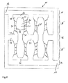
- Figure 1 shows a flow design for a fuel cell, in particular a proton exchange membrane fuel cell, according to a first embodiment of the present invention.
- the flow design 10 comprises a reactant gas inlet 12, a reactant gas outlet 14 and a plurality of reactant gas flow channels therebetween.
- the reactant gas flow channels are arranged so as to define a reaction zone 16, wherein flow channels are arranged in an interdigitated configuration.
- An inlet distribution area 18 is arranged upstream of the reaction zone 16 for receiving reactant gas from the reactant gas inlet 12 and delivering it to the reaction zone 16.
- the reaction zone 16 presents an interdigitated flow field comprising a plurality of flow channels 20 separated form one another by ribs 22.
- the reactant gas flows from the inlet distribution area 18, into the flow channels 20 fluidly connected thereto towards an outlet distribution area 24.
- the outlet distribution area 24 collects the reactant gas from the flow channels 20 fluidly connected thereto for delivery to the reactant gas outlet 14 for evacuating the reactant gas form the flow design 10.
- the ribs 22 are provided with a plurality of interconnecting channels 28 connecting two neighbouring flow channels 20.
- Such interconnecting channels 28 allow some of the reactant gas to flow more freely from one flow channel 20 to another.
- the convective flow through the interconnecting channels 28 induces some convective flow in the GDL.
- the pressure drop in the interconnecting channels 28 generates a pressure difference between the flow channels 20, thus also resulting in convective flow in the GDL.
- the interconnecting channels 28 in the ribs 22 between neighbouring flow channels 20 allow improving the overall performance of the fuel cell by selectively influencing pressure drop, mass transport and mass flow rate.
- the ribs 22 are configured such that they have variable width, gradually narrowing towards a central portion 30 of the ribs 22. Indeed, the ribs 22 are narrow in the central portion 30 of the rib 22 and widen in direction of the end portions 32, 34 of the rib 22. Such ribs 22 cause the flow channels 20 to have a bulging cross-section. Indeed, the flow channels 20 are narrow in the end portions 36, 38 of the flow channels 20 and widen in direction of the central portion 40 of the flow channels 20. The narrowing ribs 22 or bulging flow channels 20 allow influencing the pressure drop in the flow channels 20 and thus rendering the mass flow rate over the ribs 22 more constant over the length of the ribs 22.
- Figure 2 shows a flow design for a fuel cell, in particular a proton exchange membrane fuel cell, according to a second embodiment of the present invention.
- the reaction zone 16 is split into two separate portions 16', 16", wherein each of these portions 16', 16" comprises a flow channel design similar to the one of reaction zone 16 of Figure 1 . Not all details explained above are explained again for Figure 2 . Same reference signs denote same features as in Fig.1 .
- the main difference between the two embodiments is indeed the dividing of the reaction zone 16 into a first reaction zone portion 16' and a second reaction zone portion 16" with an intermediate distribution area 42 arranged therebetween.
- the intermediate distribution area 42 creates a fluid connection from the first reaction zone portion 16' to the second reaction zone portion 16", thus allowing the reactant gas to flow from the inlet distribution area 18 to the outlet distribution area 24.
- Figure 2 shows the splitting of the reaction zone into two portions, it should be noted that more than two portions are also possible. With an increasing number of portions, the gas flow is forced to alternate between flow channels more often, thereby enhancing the reactant gas flow through the fuel cell.
- first and second reaction zone portions 16', 16" need not be identical. Indeed, there may be differences in the number, lengths and widths of the flow channels 20. Similarly, the number, orientation, position and cross-section of the interconnecting channels 28 may also vary from one reaction zone portion to another. As an example, in Figure 2 , the number of interconnecting channels 28 in the second reaction zone portion 16" is higher than in the first reaction zone portion 16'.
- the narrowest section of the rib 22 is centrally over the length of the rib.
- the narrow section may in fact be located anywhere along the length of the rib. As such, it may be possible to have the narrow section arranged near one of the distribution areas and widening towards another one of the distribution areas.
- the narrowing or widening of the rib is not necessarily continuous, symmetric or regular. An irregular shape of the rib will consequently also produce an irregular shape of the neighbouring flow channel 20.
Landscapes
- Life Sciences & Earth Sciences (AREA)
- Engineering & Computer Science (AREA)
- Manufacturing & Machinery (AREA)
- Sustainable Development (AREA)
- Sustainable Energy (AREA)
- Chemical & Material Sciences (AREA)
- Chemical Kinetics & Catalysis (AREA)
- Electrochemistry (AREA)
- General Chemical & Material Sciences (AREA)
- Fuel Cell (AREA)
Priority Applications (1)
| Application Number | Priority Date | Filing Date | Title |
|---|---|---|---|
| EP11177122A EP2557621A1 (de) | 2011-08-10 | 2011-08-10 | Brennstoffzelle |
Applications Claiming Priority (1)
| Application Number | Priority Date | Filing Date | Title |
|---|---|---|---|
| EP11177122A EP2557621A1 (de) | 2011-08-10 | 2011-08-10 | Brennstoffzelle |
Publications (1)
| Publication Number | Publication Date |
|---|---|
| EP2557621A1 true EP2557621A1 (de) | 2013-02-13 |
Family
ID=44587705
Family Applications (1)
| Application Number | Title | Priority Date | Filing Date |
|---|---|---|---|
| EP11177122A Withdrawn EP2557621A1 (de) | 2011-08-10 | 2011-08-10 | Brennstoffzelle |
Country Status (1)
| Country | Link |
|---|---|
| EP (1) | EP2557621A1 (de) |
Cited By (7)
| Publication number | Priority date | Publication date | Assignee | Title |
|---|---|---|---|---|
| FR3016242A1 (fr) * | 2014-01-07 | 2015-07-10 | Commissariat Energie Atomique | Plaque de guidage d'ecoulement pour pile a combustible |
| JP2016536769A (ja) * | 2013-09-23 | 2016-11-24 | ロッキード・マーティン・アドバンスト・エナジー・ストレージ・エルエルシーLockheed Martin Advanced Energy Storage, LLC | 非伝導性の額フレームを用いたバイポーラプレート構造 |
| JP2017143051A (ja) * | 2016-02-12 | 2017-08-17 | トヨタ自動車株式会社 | 燃料電池用のセパレータ |
| CN113611890A (zh) * | 2018-11-16 | 2021-11-05 | 上海恒劲动力科技有限公司 | 一种导流通道的流线型分流结构及方法 |
| CN116516369A (zh) * | 2023-05-15 | 2023-08-01 | 陕西清能动力科技有限公司 | 电解槽叶片式波浪形流场结构 |
| WO2025003883A3 (en) * | 2023-06-26 | 2025-03-20 | Universidade Do Porto | Electrochemical device and respective uses |
| CN120330730A (zh) * | 2025-05-15 | 2025-07-18 | 内蒙古工业大学 | 一种基于太阳能发电的质子交换膜电解水制氢系统 |
Citations (3)
| Publication number | Priority date | Publication date | Assignee | Title |
|---|---|---|---|---|
| DE102005025911A1 (de) * | 2005-06-06 | 2006-12-07 | P21 - Power For The 21St Century Gmbh | Brennstoffzellenanordnungen mit verbesserter Medienzufuhr |
| US20070105000A1 (en) * | 2003-06-18 | 2007-05-10 | The Morgan Crucible Company Plc | Flow field plate geometries |
| KR20110087123A (ko) * | 2010-01-25 | 2011-08-02 | 인제대학교 산학협력단 | 보조유동유로를 가지는 연료전지용 분리판 |
-
2011
- 2011-08-10 EP EP11177122A patent/EP2557621A1/de not_active Withdrawn
Patent Citations (3)
| Publication number | Priority date | Publication date | Assignee | Title |
|---|---|---|---|---|
| US20070105000A1 (en) * | 2003-06-18 | 2007-05-10 | The Morgan Crucible Company Plc | Flow field plate geometries |
| DE102005025911A1 (de) * | 2005-06-06 | 2006-12-07 | P21 - Power For The 21St Century Gmbh | Brennstoffzellenanordnungen mit verbesserter Medienzufuhr |
| KR20110087123A (ko) * | 2010-01-25 | 2011-08-02 | 인제대학교 산학협력단 | 보조유동유로를 가지는 연료전지용 분리판 |
Non-Patent Citations (1)
| Title |
|---|
| LI X ET AL: "Review of bipolar plates in PEM fuel cells: Flow-field designs", INTERNATIONAL JOURNAL OF HYDROGEN ENERGY, ELSEVIER SCIENCE PUBLISHERS B.V., BARKING, GB, vol. 30, no. 4, 1 March 2005 (2005-03-01), pages 359 - 371, XP025263057, ISSN: 0360-3199, [retrieved on 20050301], DOI: 10.1016/J.IJHYDENE.2004.09.019 * |
Cited By (10)
| Publication number | Priority date | Publication date | Assignee | Title |
|---|---|---|---|---|
| JP2016536769A (ja) * | 2013-09-23 | 2016-11-24 | ロッキード・マーティン・アドバンスト・エナジー・ストレージ・エルエルシーLockheed Martin Advanced Energy Storage, LLC | 非伝導性の額フレームを用いたバイポーラプレート構造 |
| FR3016242A1 (fr) * | 2014-01-07 | 2015-07-10 | Commissariat Energie Atomique | Plaque de guidage d'ecoulement pour pile a combustible |
| WO2015104491A1 (fr) * | 2014-01-07 | 2015-07-16 | Commissariat à l'énergie atomique et aux énergies alternatives | Plaque de guidage d'ecoulement pour pile a combustible |
| US10218025B2 (en) | 2014-01-07 | 2019-02-26 | Commissariat à l'énergie atomique et aux énergies alternatives | Flow-guiding plate for a fuel cell |
| JP2017143051A (ja) * | 2016-02-12 | 2017-08-17 | トヨタ自動車株式会社 | 燃料電池用のセパレータ |
| CN113611890A (zh) * | 2018-11-16 | 2021-11-05 | 上海恒劲动力科技有限公司 | 一种导流通道的流线型分流结构及方法 |
| CN116516369A (zh) * | 2023-05-15 | 2023-08-01 | 陕西清能动力科技有限公司 | 电解槽叶片式波浪形流场结构 |
| WO2025003883A3 (en) * | 2023-06-26 | 2025-03-20 | Universidade Do Porto | Electrochemical device and respective uses |
| CN120330730A (zh) * | 2025-05-15 | 2025-07-18 | 内蒙古工业大学 | 一种基于太阳能发电的质子交换膜电解水制氢系统 |
| CN120330730B (zh) * | 2025-05-15 | 2026-01-06 | 内蒙古工业大学 | 一种基于太阳能发电的质子交换膜电解水制氢系统 |
Similar Documents
| Publication | Publication Date | Title |
|---|---|---|
| US9905880B2 (en) | Fuel cell stack | |
| EP2557621A1 (de) | Brennstoffzelle | |
| US8921000B2 (en) | Fuel cell | |
| US9343756B2 (en) | Fuel cell separator and fuel cell stack and reactant gas control method thereof | |
| WO2013105956A1 (en) | Fuel cell reactant flow field having impediments to flow | |
| WO2004075326A1 (ja) | 高分子電解質型燃料電池および高分子電解質型燃料電池の運転方法 | |
| CN115136366A (zh) | 具有双极流场板的燃料电池堆 | |
| US20090186253A1 (en) | Bipolar Plate Design for Passive Low Load Stability | |
| EP2500970B1 (de) | Brennstoffzelle und mit der brennstoffzelle ausgestattetes fahrzeug | |
| EP2330668B1 (de) | Polymerlektrolyt-brennstoffzelle und brennstoffzellenstapel damit | |
| JP4204348B2 (ja) | 燃料電池 | |
| KR102540924B1 (ko) | 연료전지 스택 | |
| JP2011096498A (ja) | 燃料電池積層体 | |
| US9831511B2 (en) | Fuel cell stack with improved end cell performance through a diffusion media having lower compressibility | |
| EP2387091A1 (de) | Brennstoffzelle | |
| KR101636613B1 (ko) | 연료전지용 분리판 및 이를 갖는 고온형 고분자 전해질 연료전지 | |
| JP6050158B2 (ja) | 燃料電池 | |
| US7803497B2 (en) | Fuel cell stack that utilizes an actuator to switch between interdigitated and straight flow for optimizing performance | |
| KR101060275B1 (ko) | 핀과 사행이 혼합된 연료전지용 분리판 | |
| CN115997311B (zh) | 具有在活性区域中存在的通道划分部的双极板和燃料电池堆 | |
| EP2760072A1 (de) | Polymerelektrolyt-brennstoffzelle und brennstoffzellensystem damit | |
| JP4659376B2 (ja) | 高分子電解質型燃料電池 | |
| JP2004319165A (ja) | 高分子電解質型燃料電池 | |
| CN108630968B (zh) | 用于主动控制运行期间电池压降的方法 | |
| JP2014182922A (ja) | 燃料電池スタック |
Legal Events
| Date | Code | Title | Description |
|---|---|---|---|
| PUAI | Public reference made under article 153(3) epc to a published international application that has entered the european phase |
Free format text: ORIGINAL CODE: 0009012 |
|
| AK | Designated contracting states |
Kind code of ref document: A1 Designated state(s): AL AT BE BG CH CY CZ DE DK EE ES FI FR GB GR HR HU IE IS IT LI LT LU LV MC MK MT NL NO PL PT RO RS SE SI SK SM TR |
|
| AX | Request for extension of the european patent |
Extension state: BA ME |
|
| STAA | Information on the status of an ep patent application or granted ep patent |
Free format text: STATUS: THE APPLICATION IS DEEMED TO BE WITHDRAWN |
|
| 18D | Application deemed to be withdrawn |
Effective date: 20130814 |