EP2557663B1 - Rotierende elektrische Maschine - Google Patents
Rotierende elektrische Maschine Download PDFInfo
- Publication number
- EP2557663B1 EP2557663B1 EP12168603.4A EP12168603A EP2557663B1 EP 2557663 B1 EP2557663 B1 EP 2557663B1 EP 12168603 A EP12168603 A EP 12168603A EP 2557663 B1 EP2557663 B1 EP 2557663B1
- Authority
- EP
- European Patent Office
- Prior art keywords
- winding head
- bolts
- rotor
- winding
- electric machine
- Prior art date
- Legal status (The legal status is an assumption and is not a legal conclusion. Google has not performed a legal analysis and makes no representation as to the accuracy of the status listed.)
- Active
Links
Images

Classifications
-
- H—ELECTRICITY
- H02—GENERATION; CONVERSION OR DISTRIBUTION OF ELECTRIC POWER
- H02K—DYNAMO-ELECTRIC MACHINES
- H02K3/00—Details of windings
- H02K3/46—Fastening of windings on the stator or rotor structure
- H02K3/50—Fastening of winding heads, equalising connectors, or connections thereto
- H02K3/51—Fastening of winding heads, equalising connectors, or connections thereto applicable to rotors only
-
- Y—GENERAL TAGGING OF NEW TECHNOLOGICAL DEVELOPMENTS; GENERAL TAGGING OF CROSS-SECTIONAL TECHNOLOGIES SPANNING OVER SEVERAL SECTIONS OF THE IPC; TECHNICAL SUBJECTS COVERED BY FORMER USPC CROSS-REFERENCE ART COLLECTIONS [XRACs] AND DIGESTS
- Y02—TECHNOLOGIES OR APPLICATIONS FOR MITIGATION OR ADAPTATION AGAINST CLIMATE CHANGE
- Y02E—REDUCTION OF GREENHOUSE GAS [GHG] EMISSIONS, RELATED TO ENERGY GENERATION, TRANSMISSION OR DISTRIBUTION
- Y02E10/00—Energy generation through renewable energy sources
- Y02E10/20—Hydro energy
Definitions
- the present invention relates to the field of electrical machines. It relates to a rotating electrical machine, in particular a hydro generator, according to the preamble of claim 1.
- the invention relates to a rotor of an electrical machine, in particular a hydro generator, as is used, for example, in pumped storage plants, with a rotor body which is constructed from laminated metal sheets and is held together by axial clamping bolts.
- Axial winding slots are arranged on the outer circumference of the rotor body, into which a rotor winding is inserted and held there against centrifugal force.
- the axially emerging from the rotor body, forming a winding head Winding bars are secured against centrifugal force by special support means.
- the winding head on the rotor is exposed to extreme mechanical and thermal loads.
- the winding head support against centrifugal forces can be achieved by means of bandages made of prestressed steel wire in combination with a solid one-piece steel ring.
- bandages made of prestressed steel wire in combination with a solid one-piece steel ring.
- a plurality of axially extending, mutually aligned, semi-closed grooves are provided in the circumferential direction, into each of which a ruler provided with radially running threaded bores is pushed, into which threaded bores the third tie bolts are screwed.
- a dynamo-electric machine has been proposed with a rotor bale, an annular winding head which is arranged axially next to and coaxially with the rotor bale and a support ring which is arranged radially inside the winding head and coaxial with it, with the winding head and support ring are rotatably connected to the rotor bale and the winding head and support ring are clamped together in the radial direction by tension rods which are guided through radial bores in the winding heads and in the support ring.
- the tension rods engage with their radially inner ends on the support ring and with their radially outer ends on bearing bodies which abut the winding head.
- the clear widths of the radial bores in the support body are oversized compared to the diameters of the tension rods, and the mounting of the radially inner ends of the tension rods on the support ring and the radially outer ends of the tension rods on the winding head permits a limited tilting movement of the tension rods against the radial direction. This is achieved in particular in that at least some of the ends of the tension rods are supported by means of bearing bodies which have a spherical bearing surface.
- the object is achieved by a rotating electrical machine, in particular a hydro generator, with a rotor according to claim 1.
- the bolts are designed as screw bolts and screwed into the T-hammer profile.
- Another embodiment of the invention is characterized in that a plurality of bolts with the same radial orientation are arranged one behind the other in the axial direction, and that all of the bolts are radial Alignment is attached to a common T-hammer profile or screwed into a common T-hammer profile.
- all bolts of the same radial orientation act on the winding head from the outside via a common holding element.
- Fig. 1 shows a perspective side view of a section of a rotor of a rotating electrical machine 10 according to an embodiment of the invention.
- the rotor 11 of which only a section can be seen, extends along a machine axis 20 and comprises a rotor body or a rotor laminated core 12, to which a winding head rim 13 connects at the end shown.
- Axial winding slots are arranged on the outer circumference of the rotor laminated core 12, which receive the rotor winding (not shown). From the exposed winding bars (15a, b in Fig. 2 ) form a winding head (15 in Fig. 2 ), which must be supported against the centrifugal forces (centrifugal forces) that occur during operation of the machine.
- radially oriented bolts 18 are provided in the area of the winding head 15, which extend through the winding head 15 and are fastened to the winding head rim 13.
- the entire winding head fastening must compensate for the thermal expansions of the winding. In the proposed solution, this is achieved in that the winding head attachment can move in the axial direction.
- a common, axially extending T-hammer profile 17 is provided, to which the bolts 18 for the winding head 15 are fastened.
- the T-hammer profile 17 is provided with correspondingly spaced threaded holes into which the bolts 18 designed as threaded bolts are screwed with their inner ends.
- the T-hammer profiles 17 are axially guided in axially oriented, adapted T-slots 16 of the end winding rim 13.
- the bolts 18 are supported with their heads on a common, axially extending holding element 21, which exerts radial pressure on the winding head 15, for example, via a base 22.
- Intermediate layers 23 can be arranged between the winding bars 15a and 15b in order to introduce the occurring forces evenly into the winding head 15.
- the structure of the winding head 15 shown and its attachment to the winding head rim 13 ensure that, on the one hand, the centrifugal forces which occur during operation on the winding head 15 are absorbed and introduced into the winding head rim 13, and on the other hand that the thermal expansion of the winding does not apply any shear forces builds the bolt 18, because these collectively with the entire attachment relative to the end winding rim 13 in the in Fig. 1 shown in the axial direction of movement 19 can move by the T-hammer profile 17 slides in the T-groove 16 in the axial direction.
Landscapes
- Engineering & Computer Science (AREA)
- Power Engineering (AREA)
- Insulation, Fastening Of Motor, Generator Windings (AREA)
- Iron Core Of Rotating Electric Machines (AREA)
Description
- Die vorliegende Erfindung bezieht sich auf das Gebiet der elektrischen Maschinen. Sie betrifft eine rotierende elektrische Maschine, insbesondere einen Hydro-Generator, gemäß dem Oberbegriff des Anspruchs 1.
- Die Erfindung bezieht sich auf einen Rotor einer elektrischen Maschine, insbesondere einen Hydro-Generator, wie er beispielsweise bei Pumpspeicherwerken eingesetzt wird, mit einem Rotorkörper, der aus lamellierten Blechen aufgebaut und durch axiale Spannbolzen zusammengehalten wird. Am Aussenumfang des Rotorkörpers sind axiale Wicklungsnuten angeordnet, in die eine Rotorwicklung eingelegt und dort gegen Fliehkrafteinwirkung gehalten ist. Die aus dem Rotorkörper axial austretenden, einen Wickelkopf bildenden Wicklungsstäbe sind durch spezielle Abstützmittel gegen Fliehkrafteinwirkung gesichert.
- Bei solchen Maschinen ist der Wickelkopf am Rotor extremen mechanischen und thermischen Belastungen ausgesetzt. Die Wickelkopfabstützung gegen Fliehkräfte kann dabei mittels Bandagen aus vorgespanntem Stahldraht in Kombination mit einem massiven einteiligen Stahlring .erfolgen. Durch die aufwendigen Montagehilfsmittel, die Transportabmessungen und durch die Gewichtslimitierung des Rotors ergeben sich jedoch Grenzen. Für Rotoren von Wasserkraftmaschinen mit großen Dimensionen muss der Zusammenbau direkt auf einem Montageplatz im Kraftwerk erfolgen können. Darüber hinaus beeinträchtigen große massive Stahlringe die Durchströmung des Wickelkopfes und damit dessen Kühlung.
- Die Druckschrift
WO 2008/119661 A1 beschreibt einen Rotor nach dem Oberbegriff des Anspruchs 1. - Aus der Druckschrift
DE 195 13 457 ist es nun bekannt, an den Endblechen des Rotorkörpers Pressfinger anzuordnen, sowie einen Stützring aus mindestens zwei von in Axialrichtung beabstandeten Ringen vorzusehen, die sich an ihrem Innenumfang auf der Nabe abstützen, wobei die Ringe im achsnahen Abschnitt des Rotorkörpers zusammen mit den Pressfingern mit dem den Rotorkörper axial durchsetzenden ersten Zugbolzen zusammengespannt sind. Im achsferneren Abschnitt sind zweite Zugbolzen vorgesehen, welche nur die besagten Ringe axial durchsetzen und die Ringe axial zusammenspannen. Schliesslich sind dritte, den Wickelkopf radial durchsetzende Zugbolzen vorgesehen, welche zumindest am Aussenumfang des axial gesehen äußersten Ringes angreifen. - Am Außenumfang aller Ringe ist in Umfangsrichtung verteilt eine Vielzahl von axial verlaufenden, miteinander fluchtenden, halbgeschlossene Nuten vorgesehen, in welche je ein mit radial verlaufenden Gewindebohrungen versehenes Lineal geschoben ist, in welche Gewindebohrungen die besagten dritten Zugbolzen eingeschraubt sind. Dies ergibt eine einfach herzustellende und sichere radiale Abstützung.
- Die axiale thermische Dehnung der Wicklung bei Erwärmung kann bei dieser bekannten Anordnung jedoch dazu führen, dass die Wicklung auf die Wickelkopfbolzen (die dritten Bolzen) drückt und diese so eine unerwünschte und nicht tolerierbare Biegung erfahren.
- In der Druckschrift
WO 2010/115481 ist zur Vermeidung dieser Probleme eine dynamoelektrische Maschine vorgeschlagen worden, mit einem Rotorballen, einem ringförmigen Wickelkopf, der axial neben dem Rotorballen und zu diesem koaxial angeordnet ist und einem Tragring, der radial innerhalb des Wickelkopfes und zu diesem koaxial angeordnet ist, wobei Wickelkopf und Tragring mit dem Rotorballen drehfest verbunden sind und Wickelkopf und Tragring in radialer Richtung durch Zugstäbe miteinander verspannt sind, die durch Radialbohrungen in den Wickelköpfen und im Tragring hindurchgeführt sind. Die Zugstäbe greifen dabei mit ihren radial inneren Enden am Tragring und mit ihren radial äußeren Enden an Lagerkörpern an, die am Wickelkopf anliegen. Die lichten Weiten der Radialbohrungen im Tragkörper weisen gegenüber den Durchmessern der Zugstäbe Übermaß auf und die Lagerung der radial inneren Enden der Zugstäbe am Tragring und der radial äußeren Enden der Zugstäbe am Wickelkopf erlaubt eine begrenzte Kippbewegung der Zugstäbe gegen die Radialrichtung. Dies wird insbesondere dadurch erreicht, dass wenigstens einige der Enden der Zugstäbe mittels Lagerkörpern gelagert sind, die eine sphärische Lagerfläche aufweisen. - Nachteilig ist bei dieser Lösung jedoch, dass alle Zugstäbe einzeln für eine Kippbewegung vorbereitet werden müssen, was einen erheblichen konstruktiven und montagetechnischen Aufwand zur Folge hat.
- Es ist daher eine Aufgabe der Erfindung, eine rotierende elektrische Maschine der eingangs genannten Art zu schaffen, welche die Nachteile der bekannten Maschinen im Bezug auf die Fliehkraftsicherung der Wickelköpfe vermeidet und sich durch eine konstruktiv einfache und wirksame Neutralisierung der thermischen Ausdehnung der Wickelköpfe auszeichnet.
- Die Aufgabe wird durch eine rotierende elektrische Maschine, insbesondere Hydro-Generator, mit einem Rotor gemäß dem Anspruch 1 gelöst.
- Gemäss einer Ausgestaltung der Erfindung sind die Bolzen als Schraubbolzen ausgebildet und in das T-Hammerprofil eingeschraubt.
- Eine andere Ausgestaltung der Erfindung zeichnet sich dadurch aus, dass in axialer Richtung jeweils mehrere Bolzen mit derselben radialen Ausrichtung hintereinander angeordnet sind, und dass alle Bolzen derselben radialen Ausrichtung an einem gemeinsamen T-Hammerprofil befestigt bzw. in ein gemeinsames T-Hammerprofil eingeschraubt sind.
- Insbesondere wirken alle Bolzen derselben radialen Ausrichtung über ein gemeinsames Halteelement von außen auf den Wickelkopf ein.
- Die Erfindung soll nachfolgend anhand von Ausführungsbeispielen im Zusammenhang mit der Zeichnung näher erläutert werden. Es zeigen
- Fig. 1
- in einer perspektivischen Seitenansicht einen Ausschnitt aus einem Rotor einer rotierende elektrische Maschine gemäß einem Ausführungsbeispiel der Erfindung; und
- Fig. 2
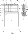
- die Anordnung und Befestigung des Wickelkopfes bei der Maschine aus
Fig. 1 in einer Ansicht quer zur Maschinenachse (Fig. 2a ) und in einer Ansicht in Achsenrichtung (Fig. 2b ). -
Fig. 1 zeigt in einer perspektivischen Seitenansicht einen Ausschnitt aus einem Rotor einer rotierenden elektrischen Maschine 10 gemäß einem Ausführungsbeispiel der Erfindung. Der Rotor 11, von dem nur ein Ausschnitt zu sehen ist, erstreckt sich entlang einer Maschinenachse 20 und umfasst einen Rotorkörper beziehungsweise ein Rotorblechpaket 12, an welches an dem dargestellten Ende ein Wickelkopf-Rim 13 anschliesst. - Auf dem Außenumfang des Rotorblechpakets 12 sind axiale Wicklungsnuten angeordnet, welche die (nicht dargestellte) Rotorwicklung aufnehmen. Die aus dem Rotorblechpaket 12 heraustretenden frei liegenden Wicklungsstäbe (15a,b in
Fig. 2 ) bilden einen Wickelkopf (15 inFig. 2 ), der gegen die beim Betrieb der Maschine auftretenden Zentrifugalkräfte (Fliehkräfte) abgestützt werden muss. - Hierzu sind im Bereich des Wickelkopfes 15 radial orientierte Bolzen 18 vorgesehen, die durch den Wickelkopf 15 hindurch reichen und am Wickelkopf-Rim 13 befestigt sind. Um eine freie axiale Ausdehnung des Wickelkopfes 15 und dessen Befestigung zu ermöglichen, muss die ganze Wickelkopf-Befestigung die thermischen Ausdehnungen der Wicklung kompensieren. Bei der vorgeschlagenen Lösung wird dies dadurch erreicht, dass sich die Wickelkopf-Befestigung in axialer Richtung bewegen kann. Für jede axiale Reihe von Bolzen 18 mit gleicher radialer Ausrichtung ist jeweils ein gemeinsames, sich axial erstreckendes T-Hammerprofil 17 vorgesehen, an welchem die Bolzen 18 für den Wickelkopf 15 befestigt sind. Das T-Hammerprofil 17 ist dazu mit entsprechend beabstandeten Gewindelöchern versehen, in welche die als Gewindebolzen ausgebildeten Bolzen 18 mit ihren inneren Enden eingeschraubt sind. Die T-Hammerprofile 17 sind in axial orientierten, angepassten T-Nuten 16 des Wickelkopf-Rims 13 axial geführt. Auf der Aussenseite stützen sich die Bolzen 18 mit ihrem Kopf an einem gemeinsamen, sich axial erstreckenden Halteelement 21 ab, welches beispielsweise über eine Unterlage 22 radialen Druck auf den Wickelkopf 15 ausübt. Zwischen den Wicklungsstäben 15a und 15b können Zwischenlagen 23 angeordnet sein, um die auftretenden Kräfte gleichmäßig in den Wickelkopf 15 einzuleiten.
- Durch den gezeigten Aufbau des Wickelkopfes 15 und seiner Befestigung am Wickelkopf-Rim 13 wird erreicht, dass einerseits die im Betrieb am Wickelkopf 15 auftretenden Fliehkräfte aufgefangen und in den Wickelkopf-Rim 13 eingeleitet werden, und dass andererseits die thermische Ausdehnung der Wicklung keine Scherkräfte an den Bolzen 18 aufbaut, weil diese sich kollektiv mit der gesamten Befestigung relativ zum Wickelkopf-Rim 13 in der in
Fig. 1 eingezeichneten axialen Bewegungsrichtung 19 bewegen können, indem das T-Hammerprofil 17 in der T-Nut 16 in axialer Richtung gleitet. -
- 10
- rotierende elektrische Maschine (insb. Hydro-Generator)
- 11
- Rotor
- 12
- Rotorblechpaket
- 13
- Wickelkopf-Rim
- 14
- Wicklungsnut
- 15
- Wickelkopf
- 15a,b
- Wicklungstab
- 16
- T-Nut
- 17
- T-Hammerprofil
- 18
- Bolzen
- 19
- Bewegungsrichtung
- 20
- Maschinenachse
- 21
- Halteelement
- 22
- Unterlage
- 23
- Zwischenlage
Claims (4)
- Rotierende elektrische Maschine (10), insbesondere Hydro-Generator, mit einem Rotor (11), welcher ein sich in Richtung einer Maschinenachse (20) erstreckendes Rotorblechpaket (12) mit einer Rotorwicklung (15a,b) umfasst, wobei die Rotorwicklung (15a,b) an den Enden des Rotorblechpakets (12) jeweils einen Wickelkopf (15) ausbildet, der zum Abfangen von Zentrifugalkräften mittels radial durch den Wickelkopf (15) hindurchgehender Bolzen (18) an einem sich in axialer Richtung an das Rotorblechpaket (12) anschliessenden, konzentrisch innerhalb des Wickelkopfes (15) angeordneten Wickelkopf-Rim (13) befestigt ist, und wobei die Befestigung (16, 17, 18, 21) zur sicheren Aufnahme von axialen Dehnungen des Wickelkopfes (15) ausgebildet ist, wobei die Bolzen (18) am Wickelkopf-Rim (13) jeweils an einem sich in axialer Richtung erstreckenden T-Hammerprofil (17) befestigt sind, dadurch gekennzeichnet, dass das T-Hammerprofil axial verschieblich in einer zugehörigen axialen T-Nut im Wickelkopf-Rim (13) gelagert ist.
- Rotierende elektrische Maschine nach Anspruch 1, dadurch gekennzeichnet, dass die Bolzen (18) als Schraubbolzen ausgebildet und in das T-Hammerprofil (17) eingeschraubt sind.
- Rotierende elektrische Maschine nach Anspruch 1 oder 2, dadurch gekennzeichnet, dass in axialer Richtung jeweils mehrere Bolzen (18) mit derselben radialen Ausrichtung hintereinander angeordnet sind, und dass alle Bolzen (18) derselben radialen Ausrichtung an einem gemeinsamen T-Hammerprofil (17) befestigt bzw. in ein gemeinsames T-Hammerprofil (17) eingeschraubt sind.
- Rotierende elektrische Maschine nach Anspruch 3, dadurch gekennzeichnet, dass alle Bolzen (18) derselben radialen Ausrichtung über ein gemeinsames Halteelement (21) von außen auf den Wickelkopf (15) einwirken.
Applications Claiming Priority (1)
| Application Number | Priority Date | Filing Date | Title |
|---|---|---|---|
| DE102011109953 | 2011-08-11 |
Publications (3)
| Publication Number | Publication Date |
|---|---|
| EP2557663A2 EP2557663A2 (de) | 2013-02-13 |
| EP2557663A3 EP2557663A3 (de) | 2017-05-10 |
| EP2557663B1 true EP2557663B1 (de) | 2020-05-20 |
Family
ID=46172685
Family Applications (1)
| Application Number | Title | Priority Date | Filing Date |
|---|---|---|---|
| EP12168603.4A Active EP2557663B1 (de) | 2011-08-11 | 2012-05-21 | Rotierende elektrische Maschine |
Country Status (8)
| Country | Link |
|---|---|
| US (1) | US9130432B2 (de) |
| EP (1) | EP2557663B1 (de) |
| JP (1) | JP5935136B2 (de) |
| CN (1) | CN102957251B (de) |
| CA (1) | CA2785140C (de) |
| ES (1) | ES2805325T3 (de) |
| PT (1) | PT2557663T (de) |
| RU (1) | RU2541047C2 (de) |
Families Citing this family (3)
| Publication number | Priority date | Publication date | Assignee | Title |
|---|---|---|---|---|
| DE102019118623A1 (de) * | 2019-07-10 | 2021-01-14 | Voith Patent Gmbh | Rotor für eine elektrische Maschine |
| DE102019118625A1 (de) * | 2019-07-10 | 2021-01-14 | Voith Patent Gmbh | Rotor für eine elektrische Maschine |
| DE102022104000A1 (de) * | 2022-02-21 | 2023-08-24 | Voith Patent Gmbh | Rotor für eine elektrische Maschine |
Family Cites Families (15)
| Publication number | Priority date | Publication date | Assignee | Title |
|---|---|---|---|---|
| US2712085A (en) * | 1955-06-28 | M willyoung | ||
| DE573444C (de) * | 1931-05-10 | 1933-04-01 | Aeg | Einrichtung an elektrischen Maschinen grosser Baulaenge zur Erleichterung der Waermebewegung ihrer Wicklungsteile |
| US3614498A (en) * | 1970-11-16 | 1971-10-19 | Asea Ab | Winding coil support means |
| JPS58182443A (ja) * | 1982-04-20 | 1983-10-25 | Toshiba Corp | 回転電機の回転子 |
| US5264750A (en) * | 1992-06-17 | 1993-11-23 | General Electric Company | Strain energy control plane for generator rotor field |
| RU2043690C1 (ru) * | 1992-07-06 | 1995-09-10 | Акционерное общество закрытого типа НИИ "Сибэлектротяжмаш" | Ротор явнополюсной синхронной электрической машины |
| DE19513457A1 (de) * | 1995-04-08 | 1996-10-10 | Abb Management Ag | Rotor einer elektrischen Maschine |
| DE19519127C1 (de) * | 1995-05-16 | 1996-09-12 | Siemens Ag | Dynamoelektrische Maschine mit bewickeltem Rotor |
| JP3410881B2 (ja) * | 1995-11-06 | 2003-05-26 | 株式会社東芝 | 回転子巻線端部の支持装置 |
| JPH09308165A (ja) | 1996-05-15 | 1997-11-28 | Toshiba Corp | 回転電機の回転子 |
| JP3788386B2 (ja) * | 2002-04-18 | 2006-06-21 | 株式会社日立製作所 | 発電機 |
| RU2275728C1 (ru) * | 2004-12-14 | 2006-04-27 | Юрий Сергеевич Голубенцев | Статор электрической машины |
| EP2132859B1 (de) * | 2007-03-30 | 2013-02-27 | Alstom Technology Ltd | Rotor einer elektrischen maschine |
| DE102009016516A1 (de) | 2009-04-08 | 2010-10-21 | Voith Patent Gmbh | Dynamoelektrische Maschine |
| JP2011024331A (ja) | 2009-07-15 | 2011-02-03 | Hitachi Ltd | 回転電機 |
-
2012
- 2012-05-21 EP EP12168603.4A patent/EP2557663B1/de active Active
- 2012-05-21 PT PT121686034T patent/PT2557663T/pt unknown
- 2012-05-21 ES ES12168603T patent/ES2805325T3/es active Active
- 2012-08-08 CA CA2785140A patent/CA2785140C/en active Active
- 2012-08-08 US US13/569,259 patent/US9130432B2/en active Active
- 2012-08-10 RU RU2012134398/07A patent/RU2541047C2/ru active
- 2012-08-10 CN CN201210344154.3A patent/CN102957251B/zh active Active
- 2012-08-10 JP JP2012177765A patent/JP5935136B2/ja not_active Expired - Fee Related
Non-Patent Citations (1)
| Title |
|---|
| None * |
Also Published As
| Publication number | Publication date |
|---|---|
| EP2557663A3 (de) | 2017-05-10 |
| CA2785140A1 (en) | 2013-02-11 |
| JP2013042653A (ja) | 2013-02-28 |
| ES2805325T3 (es) | 2021-02-11 |
| PT2557663T (pt) | 2020-07-16 |
| CN102957251B (zh) | 2018-01-16 |
| CN102957251A (zh) | 2013-03-06 |
| RU2541047C2 (ru) | 2015-02-10 |
| US9130432B2 (en) | 2015-09-08 |
| EP2557663A2 (de) | 2013-02-13 |
| CA2785140C (en) | 2016-05-03 |
| US20130038166A1 (en) | 2013-02-14 |
| RU2012134398A (ru) | 2014-02-20 |
| JP5935136B2 (ja) | 2016-06-15 |
Similar Documents
| Publication | Publication Date | Title |
|---|---|---|
| EP2850719B1 (de) | Statoranordnung für eine elektrische maschine | |
| DE4406400A1 (de) | Vorrichtung zur Halterung der Windungsenden einer Statorwicklung in einer dynamoelektrischen Maschine | |
| EP0736953A2 (de) | Rotor einer elektrischen Maschine | |
| DE102007000668B4 (de) | Rotor einer elektrischen Maschine | |
| DE102009057782A1 (de) | Stator für rotierende elektrische Maschine | |
| EP2569853B1 (de) | Rotor für eine dynamoelektrische maschine | |
| WO2011018438A2 (de) | Schleifringanordnung für eine rotierende elektrische maschine | |
| DE2231292C3 (de) | Wickelkopfabstützung für die Ständerwicklung elektrischer Maschinen, insb. Turbogeneratoren | |
| EP0691728B1 (de) | Vorrichtung zur Halterung der Stabenden einer Statorwicklung in einer dynamoelektrischen Maschine | |
| WO2010115481A1 (de) | Dynamoelektrische maschine | |
| EP2557663A2 (de) | Rotierende elektrische Maschine | |
| DE102020117771A1 (de) | Verfahren und Vorrichtung zum Fügen eines Wicklungspakets in ein Gehäuse eines Bauteils einer elektrischen Maschine, insbesondere eines Stators oder eines Rotors, sowie Stützvorrichtung | |
| WO2008119660A2 (de) | Rotor für eine elektrodynamische maschine | |
| EP2557664B1 (de) | Rotierende elektrische Maschine | |
| EP3510690B1 (de) | Segmentblech für ein statorblechpaket, statorblechpaket, sowie generator und windenergieanlage mit selbigen | |
| DE19504531A1 (de) | Elektrische Maschine mit Stegwelle | |
| DE19535700C2 (de) | Anordnung zur Befestigung der Wickelköpfe am Schleifringläufer einer Asynchronmaschine großen Durchmessers | |
| EP3510281B1 (de) | Rotorarretiervorrichtung für eine windenergieanlage und verfahren | |
| EP2636124B1 (de) | Generator | |
| WO2021004676A1 (de) | Rotor für eine elektrische maschine | |
| DE102008033711B3 (de) | Elektrischer Generator für die Stromgewinnung in Kraftwerken sowie Sanierverfahren | |
| DE2433464B2 (de) | ||
| EP4483476B1 (de) | Wickelkopfhalterung eines rotors für eine elektrische maschine | |
| EP1800384B1 (de) | Elektrische maschine, insbesondere generator | |
| WO2013007340A2 (de) | Tragring für den wickelkopf einer elektrodynamischen maschine |
Legal Events
| Date | Code | Title | Description |
|---|---|---|---|
| PUAI | Public reference made under article 153(3) epc to a published international application that has entered the european phase |
Free format text: ORIGINAL CODE: 0009012 |
|
| AK | Designated contracting states |
Kind code of ref document: A2 Designated state(s): AL AT BE BG CH CY CZ DE DK EE ES FI FR GB GR HR HU IE IS IT LI LT LU LV MC MK MT NL NO PL PT RO RS SE SI SK SM TR |
|
| AX | Request for extension of the european patent |
Extension state: BA ME |
|
| RAP1 | Party data changed (applicant data changed or rights of an application transferred) |
Owner name: ALSTOM RENEWABLE TECHNOLOGIES |
|
| PUAL | Search report despatched |
Free format text: ORIGINAL CODE: 0009013 |
|
| AK | Designated contracting states |
Kind code of ref document: A3 Designated state(s): AL AT BE BG CH CY CZ DE DK EE ES FI FR GB GR HR HU IE IS IT LI LT LU LV MC MK MT NL NO PL PT RO RS SE SI SK SM TR |
|
| AX | Request for extension of the european patent |
Extension state: BA ME |
|
| RIC1 | Information provided on ipc code assigned before grant |
Ipc: H02K 3/51 20060101AFI20170403BHEP |
|
| RAP1 | Party data changed (applicant data changed or rights of an application transferred) |
Owner name: GE RENEWABLE TECHNOLOGIES |
|
| STAA | Information on the status of an ep patent application or granted ep patent |
Free format text: STATUS: REQUEST FOR EXAMINATION WAS MADE |
|
| 17P | Request for examination filed |
Effective date: 20171110 |
|
| RBV | Designated contracting states (corrected) |
Designated state(s): AL AT BE BG CH CY CZ DE DK EE ES FI FR GB GR HR HU IE IS IT LI LT LU LV MC MK MT NL NO PL PT RO RS SE SI SK SM TR |
|
| STAA | Information on the status of an ep patent application or granted ep patent |
Free format text: STATUS: EXAMINATION IS IN PROGRESS |
|
| 17Q | First examination report despatched |
Effective date: 20190625 |
|
| GRAP | Despatch of communication of intention to grant a patent |
Free format text: ORIGINAL CODE: EPIDOSNIGR1 |
|
| STAA | Information on the status of an ep patent application or granted ep patent |
Free format text: STATUS: GRANT OF PATENT IS INTENDED |
|
| INTG | Intention to grant announced |
Effective date: 20191218 |
|
| GRAS | Grant fee paid |
Free format text: ORIGINAL CODE: EPIDOSNIGR3 |
|
| GRAA | (expected) grant |
Free format text: ORIGINAL CODE: 0009210 |
|
| STAA | Information on the status of an ep patent application or granted ep patent |
Free format text: STATUS: THE PATENT HAS BEEN GRANTED |
|
| AK | Designated contracting states |
Kind code of ref document: B1 Designated state(s): AL AT BE BG CH CY CZ DE DK EE ES FI FR GB GR HR HU IE IS IT LI LT LU LV MC MK MT NL NO PL PT RO RS SE SI SK SM TR |
|
| REG | Reference to a national code |
Ref country code: GB Ref legal event code: FG4D Free format text: NOT ENGLISH |
|
| REG | Reference to a national code |
Ref country code: CH Ref legal event code: EP |
|
| REG | Reference to a national code |
Ref country code: DE Ref legal event code: R096 Ref document number: 502012016089 Country of ref document: DE |
|
| REG | Reference to a national code |
Ref country code: AT Ref legal event code: REF Ref document number: 1273267 Country of ref document: AT Kind code of ref document: T Effective date: 20200615 |
|
| REG | Reference to a national code |
Ref country code: PT Ref legal event code: SC4A Ref document number: 2557663 Country of ref document: PT Date of ref document: 20200716 Kind code of ref document: T Free format text: AVAILABILITY OF NATIONAL TRANSLATION Effective date: 20200713 |
|
| REG | Reference to a national code |
Ref country code: CH Ref legal event code: NV Representative=s name: VALIPAT S.A. C/O BOVARD SA NEUCHATEL, CH |
|
| REG | Reference to a national code |
Ref country code: LT Ref legal event code: MG4D |
|
| REG | Reference to a national code |
Ref country code: NL Ref legal event code: MP Effective date: 20200520 |
|
| PG25 | Lapsed in a contracting state [announced via postgrant information from national office to epo] |
Ref country code: SE Free format text: LAPSE BECAUSE OF FAILURE TO SUBMIT A TRANSLATION OF THE DESCRIPTION OR TO PAY THE FEE WITHIN THE PRESCRIBED TIME-LIMIT Effective date: 20200520 Ref country code: NO Free format text: LAPSE BECAUSE OF FAILURE TO SUBMIT A TRANSLATION OF THE DESCRIPTION OR TO PAY THE FEE WITHIN THE PRESCRIBED TIME-LIMIT Effective date: 20200820 Ref country code: FI Free format text: LAPSE BECAUSE OF FAILURE TO SUBMIT A TRANSLATION OF THE DESCRIPTION OR TO PAY THE FEE WITHIN THE PRESCRIBED TIME-LIMIT Effective date: 20200520 Ref country code: IS Free format text: LAPSE BECAUSE OF FAILURE TO SUBMIT A TRANSLATION OF THE DESCRIPTION OR TO PAY THE FEE WITHIN THE PRESCRIBED TIME-LIMIT Effective date: 20200920 Ref country code: LT Free format text: LAPSE BECAUSE OF FAILURE TO SUBMIT A TRANSLATION OF THE DESCRIPTION OR TO PAY THE FEE WITHIN THE PRESCRIBED TIME-LIMIT Effective date: 20200520 Ref country code: GR Free format text: LAPSE BECAUSE OF FAILURE TO SUBMIT A TRANSLATION OF THE DESCRIPTION OR TO PAY THE FEE WITHIN THE PRESCRIBED TIME-LIMIT Effective date: 20200821 |
|
| PG25 | Lapsed in a contracting state [announced via postgrant information from national office to epo] |
Ref country code: BG Free format text: LAPSE BECAUSE OF FAILURE TO SUBMIT A TRANSLATION OF THE DESCRIPTION OR TO PAY THE FEE WITHIN THE PRESCRIBED TIME-LIMIT Effective date: 20200820 Ref country code: LV Free format text: LAPSE BECAUSE OF FAILURE TO SUBMIT A TRANSLATION OF THE DESCRIPTION OR TO PAY THE FEE WITHIN THE PRESCRIBED TIME-LIMIT Effective date: 20200520 Ref country code: HR Free format text: LAPSE BECAUSE OF FAILURE TO SUBMIT A TRANSLATION OF THE DESCRIPTION OR TO PAY THE FEE WITHIN THE PRESCRIBED TIME-LIMIT Effective date: 20200520 Ref country code: RS Free format text: LAPSE BECAUSE OF FAILURE TO SUBMIT A TRANSLATION OF THE DESCRIPTION OR TO PAY THE FEE WITHIN THE PRESCRIBED TIME-LIMIT Effective date: 20200520 |
|
| PG25 | Lapsed in a contracting state [announced via postgrant information from national office to epo] |
Ref country code: NL Free format text: LAPSE BECAUSE OF FAILURE TO SUBMIT A TRANSLATION OF THE DESCRIPTION OR TO PAY THE FEE WITHIN THE PRESCRIBED TIME-LIMIT Effective date: 20200520 Ref country code: AL Free format text: LAPSE BECAUSE OF FAILURE TO SUBMIT A TRANSLATION OF THE DESCRIPTION OR TO PAY THE FEE WITHIN THE PRESCRIBED TIME-LIMIT Effective date: 20200520 |
|
| PG25 | Lapsed in a contracting state [announced via postgrant information from national office to epo] |
Ref country code: EE Free format text: LAPSE BECAUSE OF FAILURE TO SUBMIT A TRANSLATION OF THE DESCRIPTION OR TO PAY THE FEE WITHIN THE PRESCRIBED TIME-LIMIT Effective date: 20200520 Ref country code: SM Free format text: LAPSE BECAUSE OF FAILURE TO SUBMIT A TRANSLATION OF THE DESCRIPTION OR TO PAY THE FEE WITHIN THE PRESCRIBED TIME-LIMIT Effective date: 20200520 Ref country code: DK Free format text: LAPSE BECAUSE OF FAILURE TO SUBMIT A TRANSLATION OF THE DESCRIPTION OR TO PAY THE FEE WITHIN THE PRESCRIBED TIME-LIMIT Effective date: 20200520 Ref country code: RO Free format text: LAPSE BECAUSE OF FAILURE TO SUBMIT A TRANSLATION OF THE DESCRIPTION OR TO PAY THE FEE WITHIN THE PRESCRIBED TIME-LIMIT Effective date: 20200520 Ref country code: CZ Free format text: LAPSE BECAUSE OF FAILURE TO SUBMIT A TRANSLATION OF THE DESCRIPTION OR TO PAY THE FEE WITHIN THE PRESCRIBED TIME-LIMIT Effective date: 20200520 |
|
| REG | Reference to a national code |
Ref country code: ES Ref legal event code: FG2A Ref document number: 2805325 Country of ref document: ES Kind code of ref document: T3 Effective date: 20210211 |
|
| REG | Reference to a national code |
Ref country code: DE Ref legal event code: R097 Ref document number: 502012016089 Country of ref document: DE |
|
| PG25 | Lapsed in a contracting state [announced via postgrant information from national office to epo] |
Ref country code: PL Free format text: LAPSE BECAUSE OF FAILURE TO SUBMIT A TRANSLATION OF THE DESCRIPTION OR TO PAY THE FEE WITHIN THE PRESCRIBED TIME-LIMIT Effective date: 20200520 Ref country code: MC Free format text: LAPSE BECAUSE OF FAILURE TO SUBMIT A TRANSLATION OF THE DESCRIPTION OR TO PAY THE FEE WITHIN THE PRESCRIBED TIME-LIMIT Effective date: 20200520 Ref country code: SK Free format text: LAPSE BECAUSE OF FAILURE TO SUBMIT A TRANSLATION OF THE DESCRIPTION OR TO PAY THE FEE WITHIN THE PRESCRIBED TIME-LIMIT Effective date: 20200520 |
|
| REG | Reference to a national code |
Ref country code: BE Ref legal event code: MM Effective date: 20200531 |
|
| PLBE | No opposition filed within time limit |
Free format text: ORIGINAL CODE: 0009261 |
|
| STAA | Information on the status of an ep patent application or granted ep patent |
Free format text: STATUS: NO OPPOSITION FILED WITHIN TIME LIMIT |
|
| PG25 | Lapsed in a contracting state [announced via postgrant information from national office to epo] |
Ref country code: LU Free format text: LAPSE BECAUSE OF NON-PAYMENT OF DUE FEES Effective date: 20200521 |
|
| 26N | No opposition filed |
Effective date: 20210223 |
|
| GBPC | Gb: european patent ceased through non-payment of renewal fee |
Effective date: 20200820 |
|
| PG25 | Lapsed in a contracting state [announced via postgrant information from national office to epo] |
Ref country code: IE Free format text: LAPSE BECAUSE OF NON-PAYMENT OF DUE FEES Effective date: 20200521 Ref country code: FR Free format text: LAPSE BECAUSE OF NON-PAYMENT OF DUE FEES Effective date: 20200720 |
|
| PG25 | Lapsed in a contracting state [announced via postgrant information from national office to epo] |
Ref country code: BE Free format text: LAPSE BECAUSE OF NON-PAYMENT OF DUE FEES Effective date: 20200531 Ref country code: SI Free format text: LAPSE BECAUSE OF FAILURE TO SUBMIT A TRANSLATION OF THE DESCRIPTION OR TO PAY THE FEE WITHIN THE PRESCRIBED TIME-LIMIT Effective date: 20200520 |
|
| PG25 | Lapsed in a contracting state [announced via postgrant information from national office to epo] |
Ref country code: GB Free format text: LAPSE BECAUSE OF NON-PAYMENT OF DUE FEES Effective date: 20200820 |
|
| PG25 | Lapsed in a contracting state [announced via postgrant information from national office to epo] |
Ref country code: TR Free format text: LAPSE BECAUSE OF FAILURE TO SUBMIT A TRANSLATION OF THE DESCRIPTION OR TO PAY THE FEE WITHIN THE PRESCRIBED TIME-LIMIT Effective date: 20200520 Ref country code: MT Free format text: LAPSE BECAUSE OF FAILURE TO SUBMIT A TRANSLATION OF THE DESCRIPTION OR TO PAY THE FEE WITHIN THE PRESCRIBED TIME-LIMIT Effective date: 20200520 Ref country code: CY Free format text: LAPSE BECAUSE OF FAILURE TO SUBMIT A TRANSLATION OF THE DESCRIPTION OR TO PAY THE FEE WITHIN THE PRESCRIBED TIME-LIMIT Effective date: 20200520 |
|
| PG25 | Lapsed in a contracting state [announced via postgrant information from national office to epo] |
Ref country code: MK Free format text: LAPSE BECAUSE OF FAILURE TO SUBMIT A TRANSLATION OF THE DESCRIPTION OR TO PAY THE FEE WITHIN THE PRESCRIBED TIME-LIMIT Effective date: 20200520 |
|
| P01 | Opt-out of the competence of the unified patent court (upc) registered |
Effective date: 20230522 |
|
| PGFP | Annual fee paid to national office [announced via postgrant information from national office to epo] |
Ref country code: DE Payment date: 20250423 Year of fee payment: 14 |
|
| PGFP | Annual fee paid to national office [announced via postgrant information from national office to epo] |
Ref country code: ES Payment date: 20250602 Year of fee payment: 14 |
|
| PGFP | Annual fee paid to national office [announced via postgrant information from national office to epo] |
Ref country code: IT Payment date: 20250423 Year of fee payment: 14 |
|
| PGFP | Annual fee paid to national office [announced via postgrant information from national office to epo] |
Ref country code: PT Payment date: 20250424 Year of fee payment: 14 |
|
| PGFP | Annual fee paid to national office [announced via postgrant information from national office to epo] |
Ref country code: CH Payment date: 20250601 Year of fee payment: 14 |
|
| PGFP | Annual fee paid to national office [announced via postgrant information from national office to epo] |
Ref country code: AT Payment date: 20250424 Year of fee payment: 14 |