EP2558032B1 - Valvule cardiaque polymère à flux optimisé - Google Patents
Valvule cardiaque polymère à flux optimisé Download PDFInfo
- Publication number
- EP2558032B1 EP2558032B1 EP11716743.7A EP11716743A EP2558032B1 EP 2558032 B1 EP2558032 B1 EP 2558032B1 EP 11716743 A EP11716743 A EP 11716743A EP 2558032 B1 EP2558032 B1 EP 2558032B1
- Authority
- EP
- European Patent Office
- Prior art keywords
- point
- leaflets
- thickness
- valve
- leaflet
- Prior art date
- Legal status (The legal status is an assumption and is not a legal conclusion. Google has not performed a legal analysis and makes no representation as to the accuracy of the status listed.)
- Active
Links
Images


Classifications
-
- A—HUMAN NECESSITIES
- A61—MEDICAL OR VETERINARY SCIENCE; HYGIENE
- A61F—FILTERS IMPLANTABLE INTO BLOOD VESSELS; PROSTHESES; DEVICES PROVIDING PATENCY TO, OR PREVENTING COLLAPSING OF, TUBULAR STRUCTURES OF THE BODY, e.g. STENTS; ORTHOPAEDIC, NURSING OR CONTRACEPTIVE DEVICES; FOMENTATION; TREATMENT OR PROTECTION OF EYES OR EARS; BANDAGES, DRESSINGS OR ABSORBENT PADS; FIRST-AID KITS
- A61F2/00—Filters implantable into blood vessels; Prostheses, i.e. artificial substitutes or replacements for parts of the body; Appliances for connecting them with the body; Devices providing patency to, or preventing collapsing of, tubular structures of the body, e.g. stents
- A61F2/02—Prostheses implantable into the body
- A61F2/24—Heart valves ; Vascular valves, e.g. venous valves; Heart implants, e.g. passive devices for improving the function of the native valve or the heart muscle; Transmyocardial revascularisation [TMR] devices; Valves implantable in the body
- A61F2/2412—Heart valves ; Vascular valves, e.g. venous valves; Heart implants, e.g. passive devices for improving the function of the native valve or the heart muscle; Transmyocardial revascularisation [TMR] devices; Valves implantable in the body with soft flexible valve members, e.g. tissue valves shaped like natural valves
- A61F2/2415—Manufacturing methods
-
- A—HUMAN NECESSITIES
- A61—MEDICAL OR VETERINARY SCIENCE; HYGIENE
- A61F—FILTERS IMPLANTABLE INTO BLOOD VESSELS; PROSTHESES; DEVICES PROVIDING PATENCY TO, OR PREVENTING COLLAPSING OF, TUBULAR STRUCTURES OF THE BODY, e.g. STENTS; ORTHOPAEDIC, NURSING OR CONTRACEPTIVE DEVICES; FOMENTATION; TREATMENT OR PROTECTION OF EYES OR EARS; BANDAGES, DRESSINGS OR ABSORBENT PADS; FIRST-AID KITS
- A61F2/00—Filters implantable into blood vessels; Prostheses, i.e. artificial substitutes or replacements for parts of the body; Appliances for connecting them with the body; Devices providing patency to, or preventing collapsing of, tubular structures of the body, e.g. stents
- A61F2/02—Prostheses implantable into the body
- A61F2/24—Heart valves ; Vascular valves, e.g. venous valves; Heart implants, e.g. passive devices for improving the function of the native valve or the heart muscle; Transmyocardial revascularisation [TMR] devices; Valves implantable in the body
- A61F2/2409—Support rings therefor, e.g. for connecting valves to tissue
-
- A—HUMAN NECESSITIES
- A61—MEDICAL OR VETERINARY SCIENCE; HYGIENE
- A61F—FILTERS IMPLANTABLE INTO BLOOD VESSELS; PROSTHESES; DEVICES PROVIDING PATENCY TO, OR PREVENTING COLLAPSING OF, TUBULAR STRUCTURES OF THE BODY, e.g. STENTS; ORTHOPAEDIC, NURSING OR CONTRACEPTIVE DEVICES; FOMENTATION; TREATMENT OR PROTECTION OF EYES OR EARS; BANDAGES, DRESSINGS OR ABSORBENT PADS; FIRST-AID KITS
- A61F2250/00—Special features of prostheses classified in groups A61F2/00 - A61F2/26 or A61F2/82 or A61F9/00 or A61F11/00 or subgroups thereof
- A61F2250/0014—Special features of prostheses classified in groups A61F2/00 - A61F2/26 or A61F2/82 or A61F9/00 or A61F11/00 or subgroups thereof having different values of a given property or geometrical feature, e.g. mechanical property or material property, at different locations within the same prosthesis
- A61F2250/0036—Special features of prostheses classified in groups A61F2/00 - A61F2/26 or A61F2/82 or A61F9/00 or A61F11/00 or subgroups thereof having different values of a given property or geometrical feature, e.g. mechanical property or material property, at different locations within the same prosthesis differing in thickness
Definitions
- Prosthetic heart valves are used to replace damaged or diseased heart valves.
- Prosthetic heart valves for human patients have been available since the 1950s.
- a heart valve prosthesis is implanted into an annular opening in a patient's heart following surgical removal of a diseased or damaged natural valve.
- the valve can be secured in the annulus of the opening through the use of sutures or pins that penetrate the host tissue and an outside edge of the valve.
- the valve can be secured in the annulus by suturing the host tissue to a sewing ring.
- Heart valves function essentially as one-way check valves for blood flow through the beating heart.
- tissue valve refers to mono or bi-leaflet heart valves having a valve orifice fabricated at least in part of a rigid, biologically compatible material such as pyrolytic carbon, and comprising essentially no biological components.
- bioprosthetic valve refers to a bi-leaflet or tri-leaflet heart valve having at least some biological components such as tissue or tissue components.
- tissue valves are obtained from a donor animal (typically bovine or porcine), and the valve may comprise either biological materials alone or biological materials with man-made supports or stents.
- polymeric valve refers to a tri-leaflet or bi-leaflet heart valve having at least some elastomeric polymer components, including at least elastomeric polymer valve leaflets.
- a tri-leaflet heart valve prosthesis typically includes an annular valve body and three flexible leaflets attached thereto.
- the valve body includes an annular base and three leaflet support posts, called a "stent," located at the circumference of the annulus.
- a sewing ring annularly coupled to the periphery of the valve body provides a place for sutures to be applied when the valve is implanted.
- the leaflets are attached to the three shaped posts along an attachment curve, and they also have a free, unattached edge end remote from the attachment curve.
- the place where two adjacent leaflets come together at one of the support posts is called the commissure, and the generally curved area on the leaflet between the free edge and the attachment curve is known as the belly of the leaflet.
- the free edges of the three leaflets come together at a "triple point" generally on the axis of the valve.
- the energy of the blood flow deflects the three leaflets away from the center of the annulus and allows blood to flow through.
- the three leaflets engage each other in a coaptive region, occlude the valve body annulus and prevent the flow of blood.
- US2004/088046 discloses heart valve leaflets comprising a plurality of stress-bearing supports, which resemble the disposition of collagen fibres in the native aortic valve and allow elastic stretching in the circumferential direction with minimal elastic stretching in the radial direction.
- the leaflets described therein have longer durability because of the unique structural characteristics, but do not require lifelong anti-coagulation because of their design and flow dynamics.
- WO93/18721 discloses a flexible leaflet heart valve to replace natural aortic or pulmonary valves of the heart, including a frame and flexible leaflets attached to the frame. Each flexible leaflet forms part of a surface of revolution having its axis of revolution substantially orthogonal to the direction of blood flow through the valve.
- the valve has improved opening characteristics under low flow conditions, and allows a large range of leaflet geometries for the same size valve.
- WO98/51239 discloses a trileaflet heart valve and envisages that the thickness of said leaflets could vary laterally across the leaflets or could alternatively vary in an axial direction.
- US 6,117,169 discloses a prosthetic heart valve including a living hinge coupling a leaflet to a valve body.
- the leaflet can be coupled through the living hinge to the valve's inner diameter, its outer diameter, or somewhere between the two diameters. Because the living hinge design of the valve is an integrated part, it can be manufactured in a single step.
- WO2007/016251 discloses medical devices for implantation within a body vessel comprising a thromboresistant material.
- the medical device can be a prosthetic valve and can comprise a support frame with one or more valve leaflets attached to the support frame.
- US2004/0024452 discloses valved prosthesis with crosslinked leaflets.
- the individual crosslinked leaflets can be selected and matched for assembly into a valve.
- the leaflet thickness, leaflet thickness variation and flexibility can be matched between a plurality of leaflets that are joined within a particular valve.
- Polymeric heart valves are required to have high durability, hemocompatibility and hemodynamic performance.
- Leaflet thickness is key to achieving these requirements.
- Prior art leaflets are made sufficiently thick in order to produce durable valves resulting in excessively high forward flow pressure loss and incomplete leaflet opening.
- the present embodiments provide the use of thicker leaflets without sacrificing forward flow pressure loss performance or incomplete leaflet opening. This is achieved by the valve according to claim 1 and the method according to claim 6.
- an exemplary polymeric heart valve including: a valve body having a central axis and including a conduit extending along the central axis from an inflow end to an outflow end; and at least three flexible leaflets extending from the body into the conduit, each of the leaflets defining an attachment curve with the body. Respective pairs of leaflets each define a commissure located proximal the body.
- the at least three leaflets define a partially open position at rest, a fully open position deflecting away from the central axis during forward blood flow along a direction from the inflow end to the outflow end, and a closed position deflecting toward the central axis during reverse blood flow along a direction from the outflow end to the inflow end.
- Some embodiments further include, for each leaflet, a respective sinus lobe in the conduit extending along the valve body and located distal the respective leaflet from the inflow end.
- the energy required to move the leaflets from the partially open position at rest to the open position during forward blood flow is less than the energy required to open the leaflets of an equivalent valve formed in a closed position at rest.
- the at least three leaflets open symmetrically in response to forward blood flow.
- the blood flow velocity through each commissure is substantially the same as that blood flow velocity through the other commissures.
- Each leaflet includes a pair of free edges coming to a tip near the central axis of the body.
- Each leaflet is characterized by at least a four point thickness profile, where: the first point in the profile is substantially located at the tip of the leaflet; the second point and the fourth point in the leaflet are substantially located at respective commissures; the third is substantially located proximal the body substantially midway along the attachment curve between the second and fourth points; and the thickness at the first point is less than the thickness of the second point and the fourth point.
- the first point has a thickness ranging between about 0.25 mm and about 0.5 mm. In some embodiments, the second point and the fourth point, each has a thickness ranging between about 0.3 mm and about 0.7 mm. In some embodiments, the third point has a thickness ranging between about 0.2 mm and about 0.4 mm.
- the first point has a thickness ranging between about 0.1 mm and about 0.25 mm. In some embodiments, the second point and the fourth point, each has a thickness ranging between about 0.15 mm and about 0.3 mm. In some embodiments, the third point has a thickness ranging between about 0.1 mm and about 0.2 mm.
- the first point has a thickness about equal to or less than two thirds of the thickness of the second and fourth points.
- the first point has a thickness about equal to or less than one half of the thickness of the second and fourth points.
- the third point has a thickness about equal to or less than two thirds of the thickness of the second and fourth points.
- the at rest opening of adjacent leaflets closest to their respective commissure ranges between 0.1 mm and 0.6.
- the at rest opening of adjacent leaflets closest to their respective commissure is 0.25 mm.
- the body, sinus lobes, and leaflets are made from a biocompatible polymer.
- the biocompatible polymer is selected from a group consisting of silicone and/or polyurethane.
- the body, sinus lobes, and leaflets are integrally constructed.
- Some embodiments further include at least one sewing ring coupled to the body above or below the sinuses and leaflets to provide a place for sutures to be applied when the valve is implanted.
- an exemplary method of making a polymeric heart valve including: forming a polymeric valve including: a valve body having a central axis and including a conduit extending along the central axis from an inflow end to an outflow end; and at least three flexible leaflets extending from the body into the conduit, each of the leaflets defining an attachment curve with the body; where respective pairs of leaflets each define a commissure located proximal the body, and where the leaflets are in a substantially closed at rest position.
- the method further includes inserting a tapered form into the conduit to maintain the at least three leaflets in a partially open position; heating the polymeric valve to fix the rest position of the at least three leaflets in the partially open position; and after the heating, removing the form.
- Each leaflet includes a pair of free edges coming to a tip near the central axis of the body.
- inserting a tapering form into the annular body to maintain the at least three leaflets in a partially open position includes using the tapered form to deflect the tip of each leaflet away from the central axis.
- the tapered form includes at least three pins, and where inserting the tapered form into the annular body includes positioning each of the at least three pins in a respective commissure.
- the tapered form includes a conical portion having a slope of at least about 25 degrees.
- heating the polymeric valve to fix the rest position of the at least three leaflets in the partially open position includes heating the valve to a temperature of about 125° C for at least about 2 hours.
- the at least three leaflets define a partially open position at rest, a fully open position deflecting away from the central axis during forward blood flow, and a closed position deflecting toward the central axis during reverse blood flow.
- the embodiment further includes trimming each of the at least three leaflets to provide a desired thickness profile.
- trimming each of the at least three leaflets includes using a hot wire to remove at least a portion of polymeric material from the leaflet.
- the desired thickness profile of each leaflet includes at least a four point thickness profile, where: the first point in the profile is substantially located at the tip of the leaflet; the second point and the fourth point in the leaflet are substantially located at respective commissures; the third is substantially located proximal the body substantially midway along the attachment curve between the second and fourth points; and the thickness at the first point is less than the thickness at the second point and the fourth point.
- the thickness profiles may be as described above.
- the body, sinus lobes, and leaflets are made from a biocompatible polymer.
- the biocompatible polymer is selected from a group consisting of silicone and/or polyurethane.
- the body and leaflets are integrally constructed.
- At least one sewing ring is coupled to the body above or below the sinuses and leaflets to provide a place for sutures to be applied when the valve is implanted.
- an exemplary polymeric heart valve which prepared by a process including the steps of: forming a polymeric valve including: a valve body having a central axis and including a conduit extending along the central axis from an inflow end to an outflow end; and at least three flexible leaflets extending from the body into the conduit, each of the leaflets defining an attachment curve with the body; where respective pairs of leaflets each define a commissure located proximal the body, and where the leaflets arc in a substantially closed at rest position.
- the process further includes the steps of: inserting a tapered form into the conduit to maintain the at least three leaflets in a partially open position; heating the polymeric valve to fix the rest position of the at least three leaflets in the partially open position; and after the heating, removing the form.
- Various embodiments may include any of the features described above, alone or in any suitable combination.
- the present embodiments provide at least the following advantages over prior art prosthetic heart valves.
- First, setting the leaflets in an open position ensures low forward flow pressure loss.
- Second, the leaflet geometry ensures symmetric opening to prevent low fluid velocities in the commissures between the leaflets and in the sinus lobes distal to each leaflet.
- the present technology relates to polymeric heart valves that increase valve reliability and reduce forward flow pressure loss.
- the polymeric heart valve includes a body and at least three flexible leaflets, with pairs of adjacent leaflets defining commissures located therebetween.
- the valve leaflets are formed in a partially open position at rest to ensure low forward flow pressure loss and symmetric opening.
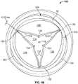
- Figs. 1A and 1B show one embodiment of a polymeric heart valve 100.
- the heart valve includes an annular, generally cylindrical elastomeric valve body 110 having a conduit 115 extending along and about a central axis 116 from an inflow end to an outflow end.
- Valve 100 includes at least three flexible leaflets 130 each having a pair of free edges 132 coming to a tip 134 near the central axis 116 of the body 110, Each of the leaflets attach to the valve body 110 at an attached edge 133, defining an attachment curve.
- Each pair of leaflets defines a commissure 135 therebetween.
- valve body 110 includes at least three sinus lobes 120 extending in an axial direction about the body 110, each located distal a respective leaflet.
- the body 110, the sinus lobes 120, and the leaflets 130 can be made from a biocompatible polymer.
- the leaflets 130 are cast in a partially open position at rest (i.e. in the absence of forward or reverse fluid pressure against the valve).
- the open area of the valve in the at rest position e.g., the open cross sectional area presented to fluid flow through the valve
- the open area in the partially open at rest positions may be greater than 5%, 10%, 25% or more of the open area, e.g., in the range of 5-10%, 10-20%, 10-30%, or any other suitable range.
- Fig. 7 illustrates the improved forward flow for an exemplary valve formed in the partially open at rest position, relative to the equivalent valve formed in the closed at rest position.
- the partially open rest position leaflet 130 geometry helps ensure a symmetric opening of the leaflets in response to forward flow.
- the valve can avoid unwanted adhesion of free edges of one or more pairs of adjacent leaflets 130 to one another. This prevents low fluid velocities in the commissure 135 between the leaflets 130 and in the sinus lobes 120 distal to each leaflet 130.
- avoiding low fluid flow and/or asymmetric flow patterns can lead to a reduction or even elimination of deleterious effects, e.g.,thrombosis.
- the at rest opening of adjacent leaflets 130 closest to their respective commissure ranges between 0.1 mm and 0.6 mm, as shown in detail in Fig. 1C . In one embodiment, the at rest opening is 0.25 mm.
- a form e.g. a tapered form
- the valve body 110 forcing the leaflets 130 into the partially open position after which the valve 100 is annealed giving the leaflets 130 a partially open "memory" position which persists after removal of the form.
- any appropriately shaped form e.g. a cylindrical form
- each leaflet 130 engages the adjacent leaflets 130 along the free edges 132, causing the valve 100 to seal against reverse flow.
- Fig. 2 is a leaflet thickness profile of the leaflets 130 of the polymeric heart valve 100 of Figs. 1A and 1B .
- each leaflet 130a, 130b, and 130c is characterized by a four point thickness profile.
- point 1 is located near (e.g., within about 1 mm of) the tip of the leaflet 130a.
- Points 2 and 4 are located near (e.g., within about 1 mm of) the attached edge 133 of the leaflet 130a, close to (e.g., within about 1 mm of) the commissures 135 formed with adjacent leaflets 130b and 130c, respectively.
- Point 3 is located near (e.g., within about 1 mm of) attached edge 133, between points 2 and 4.
- the leaflet profile is critical for the integrity of the leaflets 130 during operation of the valve.
- the correct thickness profile provides increased valve 100 reliability and reduces forward flow pressure losses.
- the leaflet 130a will taper as it extends away from the body 110 to the tip 134.
- the thickness at point 1 is less than the thickness at points 2 and 4.
- the thickness at point 1 is less than about two thirds of the thickness at points 2 and 3, less than about two thirds of the thickness at points 2 and 4, or even less, e.g. in the range from about one half to about two thirds of the thickness at points 2 and 4.
- the leaflet 130a is thicker near its free edges 132 than its central region. Accordingly, the thickness at point 3 may be less than the thickness at points 2 and 4. For example, in some embodiments, the thickness at point 3 is about two thirds of the thickness at points 2 and 4, or even less, e.g. in the range from about one half to about two thirds of the thickness at points 2 and 4. In some embodiments, the thickness of leaflet 130a varies continuously between points 1, 2, 3, and 4 to form a "scoop" shaped profile.
- Thickness ranges for each of the thickness profile points is shown in Table 1. Thickness ranges as shown in Table 1 are suitable, e.g., for a valve used in a vascular assist device.
- Table 1 - Thickness Profile (mm) Point 1 2 3 4 Leaflet 1 0.25-0.51 0.30-0.66 0.20-0.41 0.30-0.66 Leaflet 2 0.25-0.51 0.30-0.66 0.20-0.41 0.30-0.66 Leaflet 3 0.25-0.51 0.30-0.66 0.20-0.41 0.30-0.66
- the above tables show different thickness profiles, however according to the present invention the thickness at the first
- the leaflets 130 may have a thickness profile as shown in Table 2 above. Note that this example maintains the thickness profile rations of the example from Table 1. but is overall thinner. In various embodiments, the ratios may be maintained but other thicknesses provided. In further embodiments, other suitable ratios may be used.
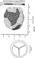
- Figs. 3A and 3B show mean flow velocity plots for an exemplary valve formed with a closed rest position ( Fig. 3A ) according to the prior art and an equivalent exemplary valve 100 formed in the partially open rest position ( Fig. 3B ) according to the embodiments described herein.
- a mock circulatory loop was used to evaluate the flow fields during the entire cardiac cycle the two polymeric trileaflet heart valves in the aortic position. Each valve was manufactured within a conduit (as shown in Fig. 1A ) and attached to the outlet port of the 50 cc ventricle in the mock loop.
- the fluid used in the loop was a Newtonian blood analog consisting of 12% glycerin, 28% water and 60% sodium iodide solution by volume to match as closely to the refractive index of the conduit as possible.
- the fluid had a density of 1.91 g/cm 3 , a kinematic viscosity of 3.77 centistokes and an index of refraction of 1.51.
- Each valve was tested at a heart rate of 90 beats/minute, a flow rate of 4.5 liters/minute, and a systolic duration of 35%.
- the flow rate in the loop was measured using an ultrasonic flow probe (Transonic Systems, Ithaca, NY) located approximately eight inches downstream of the valve. Near physiologic atrial and aortic pressures were maintained for both valves during data collection.
- a one-dimensional laser Doppler velocimetry system was used to measure the axial velocities along the flow at 60 points in the flow field.
- FIG. 1A two planes of data were collected at 0.7 inches from the base of the leaflets 130 and 1 inch from the base of the leaflets 130. For each spatial location (0.1 inches apart), 10,000 velocity measurements were acquired over a sufficient number of cardiac cycles. During post processing, the data was divided into 10 ms time bins over the entire cardiac cycle (667 ms).
- Figures 3A and 3B display mean velocities at peak systole for the closed and partially open polymeric valves, respectively.
- Fig. 3A (closed at rest valve) clearly shows asymmetric flow fields with retrograde flow up to 1 m/s encompassing a significant amount of area behind one of the leaflets (lower left hand corner) suggesting this leaflet does not open completely. There is a minor amount of retrograde flow behind the other two leaflets with the highest retrograde mean velocity of -0.98 m/s. These retrograde flow fields indicate areas that have the potential for thrombus formation. Peak mean velocities near 2.79 m/s are present during peak systole in the central orifice and persist for approximately 30 ms (not shown) of the cardiac cycle. The maximum velocity measured was 3.56 m/s with a maximum retrograde velocity of -1.63 m/s. Flow near the commissures is significant between only two leaflets (upper right hand comer), while lower velocities are seen between the other leaflets. Lower velocities between the leaflets may lead to thrombus formation.
- Fig. 3B (partiality open at rest valve) displays a better overall flow pattern (e.g., more symmetric) at the same flow rate with significant flow between the commissures.
- the largest forward velocity measured was 3.56 m/s with the maximum retrograde velocity slightly higher at -1.67 m/s.
- all three leaflets for the open formed valve behave more consistently as evidenced by the uniform flow field. This flow field develops and remains for approximately 30 ms.
- the open formed valve has equivalent, or potentially improved hemocompatibility when compared to the closed formed valve.
- the open formed valve has excellent washing between all of the leaflets in the commissure area. For example, as indicated in Fig. 3B , flow rates of about 2.0 m/s or greater are found in the regions directly adjacent the commissure.
- the retrograde flow is symmetrically distributed behind all leaflets, which encourages proper vortex formation in the sinus lobes (e.g., substantially conformal to the sinuses of Valsalva) located distal to each leaflet.
- Fig. 4 shows an exemplary flow diagram for a method of making a valve 100 of the type described herein.
- an polymeric valve 100 e.g. a tri-leaflet valve similar to that shown in Figs. 1A and 1B
- a point 300 e.g. a triple point for a tri-leaflet valve
- the polymeric valve formed in the closed position may be constructed using any technique known in the art. For example, some embodiments employ one or more of the fabrication techniques as described in U.S. Patent No. 4,888,009 issued Dec. 19, 1908 .
- a flexible polymeric material is dissolved, e.g. in a volatile solvent, to form a homogeneous syrupy polymer solution (e.g. Angioflex Valve Pouring Solution which can be obtained from Abiomed of Danvers, MA). It should be understood that any polymeric substance can be used as the pouring solution.
- a highly-polished conduit mandrel having a portion of diameter slightly greater than that of the inside of the desired conduit 115 (e.g. the downstream conduit including sinus lobes 120 as shown in Fig. 1A ) and a wider portion beginning along a contour following the peaks and valleys of a stent, is repeatedly dipped in the polymer solution with interspersed drying periods, to form an extended conduit, e.g. of about 0.3 mm thickness. This conduit assembly is stripped from the mandrel.
- Polymer solution is then poured into the conduit.
- Angioflex valve pouring solution may be poured into the conduit along one sinus lobe curvature, gradually tilting the conduit/mandrel assembly back from a 45 degree angle to the vertical position and filling the conduit to approximately 1/8" from the top,.
- the pouring solution may then be emptied from the conduit via an adjacent sinus lobe.
- the assembly is rotated slowly while the solution dries, forming thin leaflets of flexible polymeric material integrally joined to the inside of the conduit. This process is repeated until the leaflets are a desired thickness, e.g. about 0.4 mm thick.
- the rotation process may be performed at varying orientations for different coats.
- the rotation is performed with the conduit oriented vertically while the first three coats are applied, and the angle of rotation changed, e.g. to an angle greater than 5 degrees, such as 9 degrees for the remaining pours (e.g. six additional pours).
- the valve may be placed on an automated device which controls rotation during the curing process to obtain a desired thickness profile.
- conduit-leaflet assembly After drying, the conduit-leaflet assembly is stripped from the leaflet mandrel. If additional drying is required, the conduit-leaflet assembly may be heated in an oven, e.g. 40°C until dry, e.g., for 24 hours or more.
- the ends of the conduit may be cut to a desired length.
- the outflow end of the valve 100 may be trimmed about 32 mm from the bottom of the sinus.
- At least one suture ring (not shown) is coupled to the body above or below the sinus lobes and leaflets to provide a place for sutures to be applied when the valve is implanted.
- the leaflets 130 may be trimmed, e.g. using a hot wire to very accurately remove material, to have a desired shape and thickness profile (e.g. as described in detailed above).
- a tapered form 301 is inserted into the conduit 115 the valve 100 to maintain the leaflets 130 in a partially open position.
- Tapered form 301 may have a tapered portion having any suitable shape including a conical and pyramidal shape.
- the tapered portion may come to a point, be rounded, or be truncated.
- the tapered portion may have any slope, e.g. greater than 10 degrees, 20 degrees, 25 degrees, 45 degrees or more, e.g., about 25 degrees.
- valve 100 is heated, e.g. in an oven, to anneal or otherwise cause the valve assembly to be fixed in the partially open rest position.
- Valve 1 00 may be heated to any suitable temperature, for example, a temperature greater than 100 °C, 125 °C, 130 °C, or more.
- the heating may be sustained for any suitable time, e.g. an hour or more.
- the heating may be followed by a cooling period, for example sufficient for the valve to return to room temperature, e.g., several hours or more.
- step 203 the tapered form 203 is removed. Due to the annealing process, the leaflets 130 remain in a partially open position at rest. Accordingly, the resulting device corresponds to the completed valve 100, e.g., as shown in Figs. 1A and 1B .
- the valve is molded in the open position (e.g. using pour molding techniques).
- the molded valve may contain connecting material between the leaflets which may be used to separate the leaflets.
- the connecting material may then be cut, e.g., using a laser cutting, hot wire cutting, or mechanical cutting technique to separate the leaflets.
- Laser cutting in particular is advantageous in that it may provide extremely precise cuts, allowing for a smooth, straight leaflet edge.
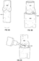
- Figs. 6A-6G show photographs illustrating an embodiment of a method for casting the leaflets of a polymeric heart valve in a partially open position at rest.
- the valve 400 is slid onto mandrel 410.
- an inflow valve stent 420 is inserted into a stent holder 430.
- the valve 400 and mandrel 410 are then inserted into the stent holder 430 until the stent 420 cradles the valve conduit as shown in Fig. 6B .
- the leaflets should be symmetrically aligned in a substantially closed position.
- the leaflets can be observed and aligned using a microscope.
- the stent 420 is tacked in place, e.g. using a UV cured adhesive ( Fig. 6C ).
- a valve forming cone 440 is placed into the valve assembly 400 so that a pin 450 is against the commissure wall on all 3 commissures.
- the valve leaflets are now partially open and that the tip of the cone is centered between the tips of the leaflet ( Fig. 4E ).
- the assembly is placed in an oven, and the valve assembly annealed such that the leaflets will remain in the partially open position once the forming cone 440 is removed.
- the oven is set at a temperature greater than 100 °C, e.g. in the range 125°C ⁇ 2 for a suitable time, e.g. 60 minutes or more.
- the assembly is removed from the oven and allowed to cool (e.g., for 2 hours or more).
- the forming cone 440 and pins 450 are removed from the valve 400.
- the valve may be inspected to verify the commissures are opened properly ( Fig. 6F ).
- the leaflets may be inspected to verify proper opening ( Fig. 6G ). It should be understood that in various embodiments the leaflets may not appear in the particular configuration shown, but should in general have a partially opened geometry which maintains the impression left by the cone 440.
Landscapes
- Health & Medical Sciences (AREA)
- Engineering & Computer Science (AREA)
- Cardiology (AREA)
- Biomedical Technology (AREA)
- Vascular Medicine (AREA)
- Oral & Maxillofacial Surgery (AREA)
- Transplantation (AREA)
- Heart & Thoracic Surgery (AREA)
- Life Sciences & Earth Sciences (AREA)
- Animal Behavior & Ethology (AREA)
- General Health & Medical Sciences (AREA)
- Public Health (AREA)
- Veterinary Medicine (AREA)
- Manufacturing & Machinery (AREA)
- Prostheses (AREA)
- Materials For Medical Uses (AREA)
Claims (10)
- Valvule cardiaque polymère (100), comprenant :un corps de valvule (110) présentant un axe central (116) et comprenant un conduit (115) s'étendant le long de l'axe central (116) d'une extrémité de flux entrant à une extrémité de flux sortant ;au moins trois cuspides flexibles (130) s'étendant à partir du corps (110) jusque dans le conduit (115), chacune des cuspides définissant une courbe de liaison avec le corps, et chaque cuspide (130) comprenant une paire de bords libres (132) rejoignant une pointe (134) proche de l'axe central (116) du corps (110) ;dans laquelle :des paires respectives des au moins trois cuspides (130) définissent chacune une commissure (135) située de manière proximale par rapport au corps ;les au moins trois cuspides (130) définissent :une position partiellement ouverte au repos ;une position entièrement ouverte, où les au moins trois cuspides (130) fléchissent pour s'éloigner de l'axe central (116) lors d'un flux sanguin vers l'avant le long d'une direction allant de l'extrémité de flux entrant à l'extrémité de flux sortant, etune position fermée, où les au moins trois cuspides (130) fléchissent pour se rapprocher de l'axe central (116) lors d'un flux sanguin vers l'arrière le long d'une direction allant de l'extrémité de flux sortant à l'extrémité de flux entrant,caractérisée en ce que chaque cuspide (130) est caractérisée par au moins un profil d'épaisseur à quatre points, dans laquelle :le premier point (1) dans le profil est en grande partie situé sur la pointe (134) de la cuspide (130) ;le deuxième point (2) et le quatrième point (4) dans la cuspide (130) se situent en grande partie sur des commissures respectives (135) ;le troisième point (3) est situé en grande partie de manière proximale par rapport au corps (110), en grande partie à mi-distance le long de la courbe de liaison entre le deuxième point (2) et le quatrième point (4), etl'épaisseur sur le premier point (1) est inférieure à l'épaisseur sur le deuxième point (2) et le quatrième point (4).
- Valvule cardiaque polymère (100) selon la revendication 1,a) dans laquelle le premier point (1) présente une épaisseur comprise entre environ 0,25 mm et environ 0,5 mm ;b) dans laquelle le deuxième point (2) et le quatrième point (4) présentent chacun une épaisseur comprise entre environ 0,3 mm et environ 0,7 mm ;c) dans laquelle le troisième point (3) présente une épaisseur comprise entre environ 0,2 mm et environ 0,4 mm ;d) dans laquelle le premier point (1) présente une épaisseur inférieure ou environ égale aux deux-tiers de l'épaisseur du deuxième point (2) et du quatrième point (4) ;e) dans laquelle le premier point (1) présente une épaisseur inférieure ou environ égale à la moitié de l'épaisseur du deuxième point (2) et du quatrième point (4), ouf) dans laquelle le troisième point (3) présente une épaisseur inférieure ou environ égale aux deux-tiers de l'épaisseur du deuxième point (2) et du quatrième point (4).
- Valvule cardiaque polymère (100) selon la revendication 1, dans laquelle l'ouverture au repos des cuspides adjacentes (130) les plus proches de leur commissure respective est comprise entre 0,1 mm et 0,6, et est facultativement de 0,25 mm.
- Valvule cardiaque polymère (100) selon la revendication 1, dans laquelle le corps (110), les lobes de sinus (120), et les cuspides (130) sont en polymère biocompatible.
- Valvule cardiaque polymère (100) selon la revendication 4, dans laquelle le polymère biocompatible est sélectionné parmi un groupe consistant en de la silicone, et/ou du polyuréthane, et dans laquelle le corps, les lobes de sinus, et les cuspides présentent facultativement une construction d'un seul tenant.
- Procédé destiné à réaliser une valvule cardiaque polymère (100), comprenant l'étape pour :former une valvule polymère présentant un corps de valvule (110) présentant un axe central (116) et comprenant un conduit (115) s'étendant le long de l'axe central (116) d'une extrémité de flux entrant à une extrémité de flux sortant, et au moins trois cuspides flexibles (130) s'étendant à partir du corps (110) jusque dans le conduit (115), chacune des cuspides (130) définissant une courbe de liaison avec le corps et comprenant une paire de bords libres (132) rejoignant une pointe (134) proche de l'axe central (116) du corps ; dans lequel des paires respectives des au moins trois cuspides (130) définissent chacune une commissure (135) située de manière proximale par rapport au corps (110), et dans lequel les au moins trois cuspides (130) sont dans une position en grande partie fermée au repos ;le procédé comprenant en outre les étapes consistant à :introduire une forme à diminution progressive (301) dans le conduit (115) afin de maintenir les au moins trois cuspides (130) dans une position partiellement ouverte ;chauffer la valvule polymère (100) pour fixer la position de repos des au moins trois cuspides (130) dans la position partiellement ouverte ;après chauffage, retirer la forme (301), dans lequel après retrait de la forme (301), les au moins trois cuspides (130) définissent une position partiellement ouverte au repos, une position entièrement ouverte s'éloignant par fléchissement de l'axe central (116) lors d'un flux sanguin vers l'avant, et une position fermée fléchissant vers l'axe central (116) lors du flux sanguin vers l'arrière, etrogner chacune des au moins trois cuspides (130) afin de fournir un profil d'épaisseur souhaité, dans lequel le profil d'épaisseur souhaité de chaque cuspide (130) comprend au moins un profil d'épaisseur à quatre points, dans lequel le premier point (1) dans le profil est en grande partie situé sur la pointe (134) de la cuspide ; le deuxième point (2) et le quatrième point (4) dans la cuspide se situent en grande partie sur des commissures respectives (135) ; le troisième point (3) est situé en grande partie de manière proximale par rapport au corps (110), en grande partie à mi-distance le long de la courbe de liaison entre le deuxième point (2) et le quatrième point (4), et dans lequel l'épaisseur sur le premier point (1) est inférieure à l'épaisseur sur le deuxième point (2) et le quatrième point (4).
- Procédé selon la revendication 6, dans lequel l'étape pour introduire une forme à diminution progressive (301) dans le corps annulaire afin de maintenir les au moins trois cuspides (130) dans une position partiellement ouverte comprend l'utilisation de la forme à diminution progressive (301) pour faire fléchir la pointe (134) de chaque cuspide (130) et l'éloigner de l'axe central (116).
- Procédé selon la revendication 7 :a) dans lequel la forme à diminution progressive (301) comprend au moins trois broches, et dans lequel l'étape pour introduire une forme à diminution progressive (301) dans le corps annulaire comprend le positionnement de chacune des au moins trois broches dans une commissure respective (135) ;b) dans lequel la forme à diminution progressive (301) comprend une portion conique présentant une pente d'au moins 25 degrés ;c) dans lequel le chauffage de la valvule polymère (100) pour fixer la position au repos des au moins trois cuspides (130) dans la position partiellement ouverte comprend le chauffage de la valvule (100) à une température d'environ 125 °C pendant au moins environ 2 heures, oud) dans lequel l'étape pour rogner chacune des au moins trois cuspides (130) comprend l'utilisation d'un fil chaud pour retirer au moins une portion du matériau polymère de la cuspide (130).
- Procédé selon la revendication 6,a) dans lequel le premier point (1) présente une épaisseur comprise entre environ 0,25 mm et environ 0,5 mm ;b) dans lequel le deuxième point (2) et le quatrième point (4) présentent chacun une épaisseur comprise entre environ 0,3 mm et environ 0,7 mm ;c) dans lequel le troisième point (3) présente une épaisseur comprise entre environ 0,2 mm et environ 0,4 mm ;d) dans lequel le premier point (1) présente une épaisseur inférieure ou environ égale aux deux-tiers de l'épaisseur du deuxième point (2) et du quatrième point (4) ;e) dans lequel le premier point (1) présente une épaisseur inférieure ou environ égale à la moitié de l'épaisseur du deuxième point (2) et du quatrième point (4), ouf) dans lequel le troisième point (3) présente une épaisseur inférieure ou environ égale aux deux-tiers de l'épaisseur du deuxième point (2) et du quatrième point (4).
- Procédé selon la revendication 6 :a) dans lequel l'ouverture au repos des cuspides adjacentes (130) les plus proches de leur commissure respective est comprise entre 0,1 mm et 0,6, et est facultativement de 0,25 mm ;b) dans lequel le corps (110), les lobes de sinus (120), et les cuspides (130) sont en polymère biocompatible ;c) dans lequel le polymère biocompatible est sélectionné parmi un groupe consistant en de la silicone, et/ou du polyuréthane, etd) dans lequel le corps (110) et les cuspides (130) présentent une construction d'un seul tenant, oue) comprenant en outre l'accouplement d'au moins un anneau de suture avec le corps (110) au-dessous ou au-dessous des sinus (120) et des cuspides (130) afin de fournir un endroit pour des sutures à appliquer lorsque la valvule (100) est implantée.
Priority Applications (1)
| Application Number | Priority Date | Filing Date | Title |
|---|---|---|---|
| EP21190736.5A EP3967270B1 (fr) | 2010-04-16 | 2011-04-14 | Un procédé de fabrication d'une valve cardiaque polymère |
Applications Claiming Priority (2)
| Application Number | Priority Date | Filing Date | Title |
|---|---|---|---|
| US12/761,891 US10512537B2 (en) | 2010-04-16 | 2010-04-16 | Flow optimized polymeric heart valve |
| PCT/US2011/032559 WO2011130558A1 (fr) | 2010-04-16 | 2011-04-14 | Valvule cardiaque polymère à flux optimisé |
Related Child Applications (1)
| Application Number | Title | Priority Date | Filing Date |
|---|---|---|---|
| EP21190736.5A Division EP3967270B1 (fr) | 2010-04-16 | 2011-04-14 | Un procédé de fabrication d'une valve cardiaque polymère |
Publications (2)
| Publication Number | Publication Date |
|---|---|
| EP2558032A1 EP2558032A1 (fr) | 2013-02-20 |
| EP2558032B1 true EP2558032B1 (fr) | 2021-08-18 |
Family
ID=44276063
Family Applications (2)
| Application Number | Title | Priority Date | Filing Date |
|---|---|---|---|
| EP11716743.7A Active EP2558032B1 (fr) | 2010-04-16 | 2011-04-14 | Valvule cardiaque polymère à flux optimisé |
| EP21190736.5A Active EP3967270B1 (fr) | 2010-04-16 | 2011-04-14 | Un procédé de fabrication d'une valve cardiaque polymère |
Family Applications After (1)
| Application Number | Title | Priority Date | Filing Date |
|---|---|---|---|
| EP21190736.5A Active EP3967270B1 (fr) | 2010-04-16 | 2011-04-14 | Un procédé de fabrication d'une valve cardiaque polymère |
Country Status (8)
| Country | Link |
|---|---|
| US (3) | US10512537B2 (fr) |
| EP (2) | EP2558032B1 (fr) |
| JP (1) | JP6038018B2 (fr) |
| AU (1) | AU2011239561B2 (fr) |
| CA (1) | CA2796357C (fr) |
| DK (1) | DK2558032T3 (fr) |
| ES (1) | ES2887311T3 (fr) |
| WO (1) | WO2011130558A1 (fr) |
Cited By (16)
| Publication number | Priority date | Publication date | Assignee | Title |
|---|---|---|---|---|
| US11311376B2 (en) | 2019-06-20 | 2022-04-26 | Neovase Tiara Inc. | Low profile prosthetic mitral valve |
| US11357622B2 (en) | 2016-01-29 | 2022-06-14 | Neovase Tiara Inc. | Prosthetic valve for avoiding obstruction of outflow |
| US11389294B2 (en) | 2012-05-30 | 2022-07-19 | Neovasc Tiara Inc. | Methods and apparatus for loading a prosthesis onto a delivery system |
| US11389291B2 (en) | 2013-04-04 | 2022-07-19 | Neovase Tiara Inc. | Methods and apparatus for delivering a prosthetic valve to a beating heart |
| US11413139B2 (en) | 2011-11-23 | 2022-08-16 | Neovasc Tiara Inc. | Sequentially deployed transcatheter mitral valve prosthesis |
| US11419720B2 (en) | 2010-05-05 | 2022-08-23 | Neovasc Tiara Inc. | Transcatheter mitral valve prosthesis |
| US11464631B2 (en) | 2016-11-21 | 2022-10-11 | Neovasc Tiara Inc. | Methods and systems for rapid retraction of a transcatheter heart valve delivery system |
| US11491006B2 (en) | 2019-04-10 | 2022-11-08 | Neovasc Tiara Inc. | Prosthetic valve with natural blood flow |
| US11497602B2 (en) | 2012-02-14 | 2022-11-15 | Neovasc Tiara Inc. | Methods and apparatus for engaging a valve prosthesis with tissue |
| US11602429B2 (en) | 2019-04-01 | 2023-03-14 | Neovasc Tiara Inc. | Controllably deployable prosthetic valve |
| US11737872B2 (en) | 2018-11-08 | 2023-08-29 | Neovasc Tiara Inc. | Ventricular deployment of a transcatheter mitral valve prosthesis |
| US11779742B2 (en) | 2019-05-20 | 2023-10-10 | Neovasc Tiara Inc. | Introducer with hemostasis mechanism |
| US11793640B2 (en) | 2017-08-25 | 2023-10-24 | Neovasc Tiara Inc. | Sequentially deployed transcatheter mitral valve prosthesis |
| US11998447B2 (en) | 2019-03-08 | 2024-06-04 | Neovasc Tiara Inc. | Retrievable prosthesis delivery system |
| US12109111B2 (en) | 2015-12-15 | 2024-10-08 | Neovasc Tiara Inc. | Transseptal delivery system |
| US12611303B2 (en) | 2022-07-21 | 2026-04-28 | Neovasc Tiara Inc. | Transcatheter mitral valve prosthesis |
Families Citing this family (58)
| Publication number | Priority date | Publication date | Assignee | Title |
|---|---|---|---|---|
| US9655720B2 (en) * | 2011-10-13 | 2017-05-23 | The Research Foundation For The State University Of New York | Polymeric heart valve |
| EP3139865B1 (fr) | 2014-05-07 | 2025-07-16 | Baylor College of Medicine | Valves flexibles artificielles |
| US10507101B2 (en) | 2014-10-13 | 2019-12-17 | W. L. Gore & Associates, Inc. | Valved conduit |
| US10653523B2 (en) | 2017-01-19 | 2020-05-19 | 4C Medical Technologies, Inc. | Systems, methods and devices for delivery systems, methods and devices for implanting prosthetic heart valves |
| US10561495B2 (en) | 2017-01-24 | 2020-02-18 | 4C Medical Technologies, Inc. | Systems, methods and devices for two-step delivery and implantation of prosthetic heart valve |
| US12029647B2 (en) | 2017-03-07 | 2024-07-09 | 4C Medical Technologies, Inc. | Systems, methods and devices for prosthetic heart valve with single valve leaflet |
| US11523940B2 (en) | 2017-03-17 | 2022-12-13 | W. L. Gore & Associates, Inc. | Delivery aids for glaucoma shunts |
| EP4732889A2 (fr) | 2017-06-07 | 2026-04-29 | Supira Medical, Inc. | Dispositifs de déplacement de fluide intravasculaire, systèmes et procédés d'utilisation |
| US12036113B2 (en) | 2017-06-14 | 2024-07-16 | 4C Medical Technologies, Inc. | Delivery of heart chamber prosthetic valve implant |
| AU2018362080B2 (en) | 2017-10-31 | 2021-09-30 | Edwards Lifesciences Corporation | Valved conduit |
| JP7319266B2 (ja) | 2017-11-13 | 2023-08-01 | シファメド・ホールディングス・エルエルシー | 血管内流体移動デバイス、システム、および使用方法 |
| DE102018201030B4 (de) | 2018-01-24 | 2025-10-16 | Kardion Gmbh | Magnetkuppelelement mit magnetischer Lagerungsfunktion |
| EP4085965A1 (fr) | 2018-02-01 | 2022-11-09 | Shifamed Holdings, LLC | Pompes à sang intravasculaires et procédés d'utilisation et de fabrication |
| US12491356B2 (en) | 2018-03-20 | 2025-12-09 | Second Heart Assist, Inc. | Circulatory assist pump |
| DE102018207594A1 (de) | 2018-05-16 | 2019-11-21 | Kardion Gmbh | Rotor, Magnetkupplungsvorrichtung, Elektromotor für ein Herzunterstützungssystem, Pumpeneinheit für ein Herzunterstützungssystem sowie Verfahren zum Herstellen eines Rotors |
| DE102018207611A1 (de) | 2018-05-16 | 2019-11-21 | Kardion Gmbh | Rotorlagerungssystem |
| DE102018207575A1 (de) | 2018-05-16 | 2019-11-21 | Kardion Gmbh | Magnetische Stirndreh-Kupplung zur Übertragung von Drehmomenten |
| DE102018208549A1 (de) | 2018-05-30 | 2019-12-05 | Kardion Gmbh | Elektronikmodul für ein Herzunterstützungssystem und Verfahren zum Herstellen eines Elektronikmoduls für ein Herzunterstützungssystem |
| DE102018208550A1 (de) | 2018-05-30 | 2019-12-05 | Kardion Gmbh | Leitungsvorrichtung zum Leiten eines Blutstroms für ein Herzunterstützungssystem, Herzunterstützungssystem und Verfahren zum Herstellen einer Leitungsvorrichtung |
| DE102018208538A1 (de) | 2018-05-30 | 2019-12-05 | Kardion Gmbh | Intravasale Blutpumpe und Verfahren zur Herstellung von elektrischen Leiterbahnen |
| DE102018208539A1 (de) | 2018-05-30 | 2019-12-05 | Kardion Gmbh | Motorgehäusemodul zum Abdichten eines Motorraums eines Motors eines Herzunterstützungssystems und Herzunterstützungssystem und Verfahren zum Montieren eines Herzunterstützungssystems |
| DE102018208541A1 (de) | 2018-05-30 | 2019-12-05 | Kardion Gmbh | Axialpumpe für ein Herzunterstützungssystem und Verfahren zum Herstellen einer Axialpumpe für ein Herzunterstützungssystem |
| DE102018210058A1 (de) | 2018-06-21 | 2019-12-24 | Kardion Gmbh | Statorschaufelvorrichtung zur Strömungsführung eines aus einer Austrittsöffnung eines Herzunterstützungssystems ausströmenden Fluids, Herzunterstützungssystem mit Statorschaufelvorrichtung, Verfahren zum Betreiben einer Statorschaufelvorrichtung und Herstellverfahren |
| DE102018210076A1 (de) | 2018-06-21 | 2019-12-24 | Kardion Gmbh | Verfahren und Vorrichtung zum Erkennen eines Verschleißzustands eines Herzunterstützungssystems, Verfahren und Vorrichtung zum Betreiben eines Herzunterstützungssystems und Herzunterstützungssystem |
| DE102018211297A1 (de) | 2018-07-09 | 2020-01-09 | Kardion Gmbh | Herzunterstützungssystem und Verfahren zur Überwachung der Integrität einer Haltestruktur eines Herzunterstützungssystems |
| DE102018211327A1 (de) | 2018-07-10 | 2020-01-16 | Kardion Gmbh | Laufrad für ein implantierbares, vaskuläres Unterstützungssystem |
| DE102018211328A1 (de) | 2018-07-10 | 2020-01-16 | Kardion Gmbh | Laufradgehäuse für ein implantierbares, vaskuläres Unterstützungssystem |
| DE102018212153A1 (de) | 2018-07-20 | 2020-01-23 | Kardion Gmbh | Zulaufleitung für eine Pumpeneinheit eines Herzunterstützungssystems, Herzunterstützungssystem und Verfahren zum Herstellen einer Zulaufleitung für eine Pumpeneinheit eines Herzunterstützungssystems |
| US12161857B2 (en) | 2018-07-31 | 2024-12-10 | Shifamed Holdings, Llc | Intravascular blood pumps and methods of use |
| EP3833410B1 (fr) | 2018-08-07 | 2025-10-08 | Kardion GmbH | Dispositif de support destiné à un dispositif d'assistance ventriculaire et procédé destiné à rincer un espace dans un dispositif de support pour un dispositif d'assistance ventriculaire |
| AU2019333136B2 (en) | 2018-08-29 | 2022-11-17 | W. L. Gore & Associates, Inc. | Drug therapy delivery systems and methods |
| US11857441B2 (en) | 2018-09-04 | 2024-01-02 | 4C Medical Technologies, Inc. | Stent loading device |
| WO2020073047A1 (fr) | 2018-10-05 | 2020-04-09 | Shifamed Holdings, Llc | Pompes à sang intravasculaires et procédés d'utilisation |
| USD977642S1 (en) | 2018-10-29 | 2023-02-07 | W. L. Gore & Associates, Inc. | Pulmonary valve conduit |
| CN113195038B (zh) | 2018-12-11 | 2025-12-30 | 瑞普医药有限公司 | 用于调节体腔中的血流量的系统、装置以及方法 |
| US11678983B2 (en) | 2018-12-12 | 2023-06-20 | W. L. Gore & Associates, Inc. | Implantable component with socket |
| US12544226B2 (en) | 2019-02-14 | 2026-02-10 | 4C Medical Technologies, Inc. | Hydrophilic skirt for paravalvular leak mitigation and fit and apposition optimization for prosthetic heart valve implants |
| US11452628B2 (en) | 2019-04-15 | 2022-09-27 | 4C Medical Technologies, Inc. | Loading systems for collapsible prosthetic heart valve devices and methods thereof |
| EP3996797A4 (fr) | 2019-07-12 | 2023-08-02 | Shifamed Holdings, LLC | Pompes à sang intravasculaires et méthode d'utilisation et procédé de fabrication |
| EP4010046A4 (fr) | 2019-08-07 | 2023-08-30 | Calomeni, Michael | Pompes sanguines à cathéter et boîtiers de pompe pliants |
| US12102815B2 (en) | 2019-09-25 | 2024-10-01 | Shifamed Holdings, Llc | Catheter blood pumps and collapsible pump housings |
| US12121713B2 (en) | 2019-09-25 | 2024-10-22 | Shifamed Holdings, Llc | Catheter blood pumps and collapsible blood conduits |
| EP4072650A4 (fr) | 2019-12-11 | 2024-01-10 | Shifamed Holdings, LLC | Pompes à sang d'aorte descendante et de veine cave |
| WO2021127503A1 (fr) | 2019-12-19 | 2021-06-24 | Shifamed Holdings, Llc | Pompes à sang intravasculaires, moteurs et commande de fluide |
| US12133797B2 (en) | 2020-01-31 | 2024-11-05 | 4C Medical Technologies, Inc. | Prosthetic heart valve delivery system: paddle attachment feature |
| US11931253B2 (en) | 2020-01-31 | 2024-03-19 | 4C Medical Technologies, Inc. | Prosthetic heart valve delivery system: ball-slide attachment |
| DE102020102474A1 (de) | 2020-01-31 | 2021-08-05 | Kardion Gmbh | Pumpe zum Fördern eines Fluids und Verfahren zum Herstellen einer Pumpe |
| US12053375B2 (en) | 2020-03-05 | 2024-08-06 | 4C Medical Technologies, Inc. | Prosthetic mitral valve with improved atrial and/or annular apposition and paravalvular leakage mitigation |
| US11992403B2 (en) | 2020-03-06 | 2024-05-28 | 4C Medical Technologies, Inc. | Devices, systems and methods for improving recapture of prosthetic heart valve device with stent frame having valve support with inwardly stent cells |
| AU2021340802A1 (en) | 2020-09-14 | 2023-05-18 | Kardion Gmbh | Cardiovascular support pump having an impeller with a variable flow area |
| AU2021383931A1 (en) | 2020-11-20 | 2023-07-06 | Kardion Gmbh | Mechanical circulatory support system with guidewire aid |
| US12527691B2 (en) | 2021-11-05 | 2026-01-20 | W. L. Gore & Associates, Inc. | Fluid drainage devices, systems, and methods |
| US12544560B2 (en) | 2022-01-14 | 2026-02-10 | Second Heart Assist, Inc. | Wireless chronic implant |
| US12594164B1 (en) | 2022-09-01 | 2026-04-07 | 4C Medical Technologies, Inc. | Prosthetic heart valve for natural blood flow |
| CN115670749A (zh) * | 2022-11-01 | 2023-02-03 | 苏州心锐医疗科技有限公司 | 一种可更换的心脏聚合物瓣膜 |
| US20240366366A1 (en) | 2023-03-24 | 2024-11-07 | 4C Medical Technologies, Inc. | Implant delivery |
| CN116509602B (zh) * | 2023-05-31 | 2024-02-06 | 苏州心岭迈德医疗科技有限公司 | 高分子心脏瓣膜及其制备方法 |
| WO2026006907A1 (fr) * | 2024-07-02 | 2026-01-08 | Tournoux Francois | Implant valvulaire pour insuffisance mitrale |
Citations (2)
| Publication number | Priority date | Publication date | Assignee | Title |
|---|---|---|---|---|
| US4863458A (en) * | 1988-12-14 | 1989-09-05 | Carbomedics Inc. | Heart valve prosthesis having configured leaflets and mounting ears |
| EP1335683A2 (fr) * | 2000-11-21 | 2003-08-20 | Rex Medical, LP | Valvule aortique percutanee |
Family Cites Families (20)
| Publication number | Priority date | Publication date | Assignee | Title |
|---|---|---|---|---|
| US4888009A (en) | 1985-04-05 | 1989-12-19 | Abiomed, Inc. | Prosthetic heart valve |
| DE3834545A1 (de) | 1988-10-11 | 1990-04-12 | Rau Guenter | Flexibles schliessorgan, insbesondere herzklappe, und verfahren zur herstellung desselben |
| US5037434A (en) | 1990-04-11 | 1991-08-06 | Carbomedics, Inc. | Bioprosthetic heart valve with elastic commissures |
| US5258023A (en) | 1992-02-12 | 1993-11-02 | Reger Medical Development, Inc. | Prosthetic heart valve |
| GB9206449D0 (en) * | 1992-03-25 | 1992-05-06 | Univ Leeds | Artificial heart valve |
| IL118149A0 (en) * | 1996-05-05 | 1996-09-12 | Rdc Rafael Dev Corp | Method for producing heart valves and heart valves produced by the method |
| GB9701479D0 (en) | 1997-01-24 | 1997-03-12 | Aortech Europ Ltd | Heart valve |
| US5843183A (en) | 1997-05-13 | 1998-12-01 | Bokros; Jack C. | Trileaflet heart valve |
| GB9715059D0 (en) * | 1997-07-18 | 1997-09-24 | Innovative Tech Ltd | Prosthetic valve sinus |
| US6117169A (en) | 1998-06-24 | 2000-09-12 | Sulzer Carbomedics Inc. | Living hinge attachment of leaflet to a valve body |
| US6287338B1 (en) | 1999-03-10 | 2001-09-11 | Sulzer Carbomedics Inc. | Pre-stressing devices incorporating materials subject to stress softening |
| US6174331B1 (en) * | 1999-07-19 | 2001-01-16 | Sulzer Carbomedics Inc. | Heart valve leaflet with reinforced free margin |
| US6371983B1 (en) * | 1999-10-04 | 2002-04-16 | Ernest Lane | Bioprosthetic heart valve |
| ATE346571T1 (de) * | 2000-09-21 | 2006-12-15 | St Jude Medical | Ventilprothesen mit blattelementen aus verstärktem kunststoff |
| US20070027535A1 (en) | 2005-07-28 | 2007-02-01 | Cook Incorporated | Implantable thromboresistant valve |
| WO2002074201A1 (fr) * | 2001-03-16 | 2002-09-26 | Mayo Foundation For Medical Education And Research | Lames valvulaires synthetiques pour remplacement ou reparation d'une valvule cardiaque |
| US20030114924A1 (en) | 2001-12-18 | 2003-06-19 | Riyad Moe | Polymer heart valve |
| US20040024452A1 (en) | 2002-08-02 | 2004-02-05 | Kruse Steven D. | Valved prostheses with preformed tissue leaflets |
| US8070800B2 (en) | 2006-05-05 | 2011-12-06 | Children's Medical Center Corporation | Transcatheter heart valve prostheses |
| CN101715330A (zh) | 2007-05-25 | 2010-05-26 | 天成医疗有限公司 | 人工心脏瓣膜 |
-
2010
- 2010-04-16 US US12/761,891 patent/US10512537B2/en active Active
-
2011
- 2011-04-14 ES ES11716743T patent/ES2887311T3/es active Active
- 2011-04-14 WO PCT/US2011/032559 patent/WO2011130558A1/fr not_active Ceased
- 2011-04-14 CA CA2796357A patent/CA2796357C/fr active Active
- 2011-04-14 EP EP11716743.7A patent/EP2558032B1/fr active Active
- 2011-04-14 JP JP2013505152A patent/JP6038018B2/ja active Active
- 2011-04-14 DK DK11716743.7T patent/DK2558032T3/da active
- 2011-04-14 AU AU2011239561A patent/AU2011239561B2/en active Active
- 2011-04-14 EP EP21190736.5A patent/EP3967270B1/fr active Active
-
2019
- 2019-10-16 US US16/654,701 patent/US11298224B2/en active Active
-
2022
- 2022-03-04 US US17/687,295 patent/US20220313425A1/en active Pending
Patent Citations (2)
| Publication number | Priority date | Publication date | Assignee | Title |
|---|---|---|---|---|
| US4863458A (en) * | 1988-12-14 | 1989-09-05 | Carbomedics Inc. | Heart valve prosthesis having configured leaflets and mounting ears |
| EP1335683A2 (fr) * | 2000-11-21 | 2003-08-20 | Rex Medical, LP | Valvule aortique percutanee |
Cited By (23)
| Publication number | Priority date | Publication date | Assignee | Title |
|---|---|---|---|---|
| US11419720B2 (en) | 2010-05-05 | 2022-08-23 | Neovasc Tiara Inc. | Transcatheter mitral valve prosthesis |
| US12053369B2 (en) | 2011-11-23 | 2024-08-06 | Neovasc Tiara Inc. | Sequentially deployed transcatheter mitral valve prosthesis |
| US11413139B2 (en) | 2011-11-23 | 2022-08-16 | Neovasc Tiara Inc. | Sequentially deployed transcatheter mitral valve prosthesis |
| US12138159B2 (en) | 2012-02-14 | 2024-11-12 | Neovasc Tiara Inc. | Methods and apparatus for engaging a valve prosthesis with tissue |
| US11497602B2 (en) | 2012-02-14 | 2022-11-15 | Neovasc Tiara Inc. | Methods and apparatus for engaging a valve prosthesis with tissue |
| US11617650B2 (en) | 2012-05-30 | 2023-04-04 | Neovasc Tiara Inc. | Methods and apparatus for loading a prosthesis onto a delivery system |
| US11389294B2 (en) | 2012-05-30 | 2022-07-19 | Neovasc Tiara Inc. | Methods and apparatus for loading a prosthesis onto a delivery system |
| US11389291B2 (en) | 2013-04-04 | 2022-07-19 | Neovase Tiara Inc. | Methods and apparatus for delivering a prosthetic valve to a beating heart |
| US12109111B2 (en) | 2015-12-15 | 2024-10-08 | Neovasc Tiara Inc. | Transseptal delivery system |
| US11357622B2 (en) | 2016-01-29 | 2022-06-14 | Neovase Tiara Inc. | Prosthetic valve for avoiding obstruction of outflow |
| US12193932B2 (en) | 2016-01-29 | 2025-01-14 | Neovasc Tiara Inc. | Prosthetic valve for avoiding obstruction of outflow |
| US11464631B2 (en) | 2016-11-21 | 2022-10-11 | Neovasc Tiara Inc. | Methods and systems for rapid retraction of a transcatheter heart valve delivery system |
| US12201524B2 (en) | 2016-11-21 | 2025-01-21 | Neovasc Tiara Inc. | Methods and systems for rapid retraction of a transcatheter heart valve delivery system |
| US11793640B2 (en) | 2017-08-25 | 2023-10-24 | Neovasc Tiara Inc. | Sequentially deployed transcatheter mitral valve prosthesis |
| US11737872B2 (en) | 2018-11-08 | 2023-08-29 | Neovasc Tiara Inc. | Ventricular deployment of a transcatheter mitral valve prosthesis |
| US11998447B2 (en) | 2019-03-08 | 2024-06-04 | Neovasc Tiara Inc. | Retrievable prosthesis delivery system |
| US11602429B2 (en) | 2019-04-01 | 2023-03-14 | Neovasc Tiara Inc. | Controllably deployable prosthetic valve |
| US12036117B2 (en) | 2019-04-10 | 2024-07-16 | Neovasc Tiara Inc. | Prosthetic valve with natural blood flow |
| US11491006B2 (en) | 2019-04-10 | 2022-11-08 | Neovasc Tiara Inc. | Prosthetic valve with natural blood flow |
| US11779742B2 (en) | 2019-05-20 | 2023-10-10 | Neovasc Tiara Inc. | Introducer with hemostasis mechanism |
| US11311376B2 (en) | 2019-06-20 | 2022-04-26 | Neovase Tiara Inc. | Low profile prosthetic mitral valve |
| US11931254B2 (en) | 2019-06-20 | 2024-03-19 | Neovasc Tiara Inc. | Low profile prosthetic mitral valve |
| US12611303B2 (en) | 2022-07-21 | 2026-04-28 | Neovasc Tiara Inc. | Transcatheter mitral valve prosthesis |
Also Published As
| Publication number | Publication date |
|---|---|
| EP2558032A1 (fr) | 2013-02-20 |
| CA2796357C (fr) | 2016-01-19 |
| US20110257738A1 (en) | 2011-10-20 |
| AU2011239561B2 (en) | 2015-04-09 |
| JP2013524890A (ja) | 2013-06-20 |
| DK2558032T3 (da) | 2021-09-27 |
| US20220313425A1 (en) | 2022-10-06 |
| CA2796357A1 (fr) | 2011-10-20 |
| EP3967270B1 (fr) | 2026-03-04 |
| US11298224B2 (en) | 2022-04-12 |
| WO2011130558A1 (fr) | 2011-10-20 |
| US10512537B2 (en) | 2019-12-24 |
| JP6038018B2 (ja) | 2016-12-07 |
| US20200046492A1 (en) | 2020-02-13 |
| AU2011239561A1 (en) | 2012-11-08 |
| EP3967270A1 (fr) | 2022-03-16 |
| ES2887311T3 (es) | 2021-12-22 |
Similar Documents
| Publication | Publication Date | Title |
|---|---|---|
| US20220313425A1 (en) | Flow optimized polymeric heart valve | |
| EP2558033B1 (fr) | Procédé de production d'une prothèse de valvule cardiaque polymère à trois feuillets | |
| US9456898B2 (en) | Heart valve prosthesis with open stent | |
| JP4287272B2 (ja) | 医療装置のための高分子弁膜構造 | |
| CA2521896C (fr) | Valvule souple concue pour etre implantee dans des vaisseaux sanguins mammaliens et dans le coeur et dotee d'un support temporaire ou permanent assure par deux stents | |
| JP4319906B2 (ja) | 心臓弁補綴具の製造方法 | |
| CN101902989A (zh) | 壁内主动脉瓣膜加强装置和加强的生物主动脉瓣膜 | |
| CN101951857A (zh) | 经皮心脏瓣膜、系统及方法 | |
| CN210019797U (zh) | 人工带瓣血管 | |
| HK40071505A (en) | Flow optimized polymeric heart valve | |
| EP4248913A1 (fr) | Dispositif de réparation d'une valvule cardiaque | |
| HK40106018A (en) | Heart valve prosthesis with open stent | |
| HK1150742A (en) | An intraparietal aortic valve reinforcement device and a reinforced biological aortic valve |
Legal Events
| Date | Code | Title | Description |
|---|---|---|---|
| PUAI | Public reference made under article 153(3) epc to a published international application that has entered the european phase |
Free format text: ORIGINAL CODE: 0009012 |
|
| 17P | Request for examination filed |
Effective date: 20121017 |
|
| AK | Designated contracting states |
Kind code of ref document: A1 Designated state(s): AL AT BE BG CH CY CZ DE DK EE ES FI FR GB GR HR HU IE IS IT LI LT LU LV MC MK MT NL NO PL PT RO RS SE SI SK SM TR |
|
| DAX | Request for extension of the european patent (deleted) | ||
| 17Q | First examination report despatched |
Effective date: 20140805 |
|
| STAA | Information on the status of an ep patent application or granted ep patent |
Free format text: STATUS: EXAMINATION IS IN PROGRESS |
|
| GRAP | Despatch of communication of intention to grant a patent |
Free format text: ORIGINAL CODE: EPIDOSNIGR1 |
|
| STAA | Information on the status of an ep patent application or granted ep patent |
Free format text: STATUS: GRANT OF PATENT IS INTENDED |
|
| INTG | Intention to grant announced |
Effective date: 20210302 |
|
| GRAS | Grant fee paid |
Free format text: ORIGINAL CODE: EPIDOSNIGR3 |
|
| GRAA | (expected) grant |
Free format text: ORIGINAL CODE: 0009210 |
|
| STAA | Information on the status of an ep patent application or granted ep patent |
Free format text: STATUS: THE PATENT HAS BEEN GRANTED |
|
| AK | Designated contracting states |
Kind code of ref document: B1 Designated state(s): AL AT BE BG CH CY CZ DE DK EE ES FI FR GB GR HR HU IE IS IT LI LT LU LV MC MK MT NL NO PL PT RO RS SE SI SK SM TR |
|
| REG | Reference to a national code |
Ref country code: GB Ref legal event code: FG4D |
|
| REG | Reference to a national code |
Ref country code: CH Ref legal event code: EP |
|
| REG | Reference to a national code |
Ref country code: DE Ref legal event code: R096 Ref document number: 602011071590 Country of ref document: DE |
|
| REG | Reference to a national code |
Ref country code: AT Ref legal event code: REF Ref document number: 1420941 Country of ref document: AT Kind code of ref document: T Effective date: 20210915 Ref country code: IE Ref legal event code: FG4D |
|
| REG | Reference to a national code |
Ref country code: DK Ref legal event code: T3 Effective date: 20210922 |
|
| REG | Reference to a national code |
Ref country code: SE Ref legal event code: TRGR |
|
| REG | Reference to a national code |
Ref country code: LT Ref legal event code: MG9D |
|
| REG | Reference to a national code |
Ref country code: NL Ref legal event code: FP Ref country code: ES Ref legal event code: FG2A Ref document number: 2887311 Country of ref document: ES Kind code of ref document: T3 Effective date: 20211222 |
|
| REG | Reference to a national code |
Ref country code: AT Ref legal event code: MK05 Ref document number: 1420941 Country of ref document: AT Kind code of ref document: T Effective date: 20210818 |
|
| PG25 | Lapsed in a contracting state [announced via postgrant information from national office to epo] |
Ref country code: RS Free format text: LAPSE BECAUSE OF FAILURE TO SUBMIT A TRANSLATION OF THE DESCRIPTION OR TO PAY THE FEE WITHIN THE PRESCRIBED TIME-LIMIT Effective date: 20210818 Ref country code: NO Free format text: LAPSE BECAUSE OF FAILURE TO SUBMIT A TRANSLATION OF THE DESCRIPTION OR TO PAY THE FEE WITHIN THE PRESCRIBED TIME-LIMIT Effective date: 20211118 Ref country code: PT Free format text: LAPSE BECAUSE OF FAILURE TO SUBMIT A TRANSLATION OF THE DESCRIPTION OR TO PAY THE FEE WITHIN THE PRESCRIBED TIME-LIMIT Effective date: 20211220 Ref country code: FI Free format text: LAPSE BECAUSE OF FAILURE TO SUBMIT A TRANSLATION OF THE DESCRIPTION OR TO PAY THE FEE WITHIN THE PRESCRIBED TIME-LIMIT Effective date: 20210818 Ref country code: BG Free format text: LAPSE BECAUSE OF FAILURE TO SUBMIT A TRANSLATION OF THE DESCRIPTION OR TO PAY THE FEE WITHIN THE PRESCRIBED TIME-LIMIT Effective date: 20211118 Ref country code: AT Free format text: LAPSE BECAUSE OF FAILURE TO SUBMIT A TRANSLATION OF THE DESCRIPTION OR TO PAY THE FEE WITHIN THE PRESCRIBED TIME-LIMIT Effective date: 20210818 Ref country code: LT Free format text: LAPSE BECAUSE OF FAILURE TO SUBMIT A TRANSLATION OF THE DESCRIPTION OR TO PAY THE FEE WITHIN THE PRESCRIBED TIME-LIMIT Effective date: 20210818 Ref country code: HR Free format text: LAPSE BECAUSE OF FAILURE TO SUBMIT A TRANSLATION OF THE DESCRIPTION OR TO PAY THE FEE WITHIN THE PRESCRIBED TIME-LIMIT Effective date: 20210818 |
|
| PG25 | Lapsed in a contracting state [announced via postgrant information from national office to epo] |
Ref country code: PL Free format text: LAPSE BECAUSE OF FAILURE TO SUBMIT A TRANSLATION OF THE DESCRIPTION OR TO PAY THE FEE WITHIN THE PRESCRIBED TIME-LIMIT Effective date: 20210818 Ref country code: LV Free format text: LAPSE BECAUSE OF FAILURE TO SUBMIT A TRANSLATION OF THE DESCRIPTION OR TO PAY THE FEE WITHIN THE PRESCRIBED TIME-LIMIT Effective date: 20210818 Ref country code: GR Free format text: LAPSE BECAUSE OF FAILURE TO SUBMIT A TRANSLATION OF THE DESCRIPTION OR TO PAY THE FEE WITHIN THE PRESCRIBED TIME-LIMIT Effective date: 20211119 |
|
| REG | Reference to a national code |
Ref country code: DE Ref legal event code: R097 Ref document number: 602011071590 Country of ref document: DE |
|
| PG25 | Lapsed in a contracting state [announced via postgrant information from national office to epo] |
Ref country code: SM Free format text: LAPSE BECAUSE OF FAILURE TO SUBMIT A TRANSLATION OF THE DESCRIPTION OR TO PAY THE FEE WITHIN THE PRESCRIBED TIME-LIMIT Effective date: 20210818 Ref country code: SK Free format text: LAPSE BECAUSE OF FAILURE TO SUBMIT A TRANSLATION OF THE DESCRIPTION OR TO PAY THE FEE WITHIN THE PRESCRIBED TIME-LIMIT Effective date: 20210818 Ref country code: RO Free format text: LAPSE BECAUSE OF FAILURE TO SUBMIT A TRANSLATION OF THE DESCRIPTION OR TO PAY THE FEE WITHIN THE PRESCRIBED TIME-LIMIT Effective date: 20210818 Ref country code: EE Free format text: LAPSE BECAUSE OF FAILURE TO SUBMIT A TRANSLATION OF THE DESCRIPTION OR TO PAY THE FEE WITHIN THE PRESCRIBED TIME-LIMIT Effective date: 20210818 Ref country code: CZ Free format text: LAPSE BECAUSE OF FAILURE TO SUBMIT A TRANSLATION OF THE DESCRIPTION OR TO PAY THE FEE WITHIN THE PRESCRIBED TIME-LIMIT Effective date: 20210818 Ref country code: AL Free format text: LAPSE BECAUSE OF FAILURE TO SUBMIT A TRANSLATION OF THE DESCRIPTION OR TO PAY THE FEE WITHIN THE PRESCRIBED TIME-LIMIT Effective date: 20210818 |
|
| PLBE | No opposition filed within time limit |
Free format text: ORIGINAL CODE: 0009261 |
|
| STAA | Information on the status of an ep patent application or granted ep patent |
Free format text: STATUS: NO OPPOSITION FILED WITHIN TIME LIMIT |
|
| 26N | No opposition filed |
Effective date: 20220519 |
|
| PG25 | Lapsed in a contracting state [announced via postgrant information from national office to epo] |
Ref country code: SI Free format text: LAPSE BECAUSE OF FAILURE TO SUBMIT A TRANSLATION OF THE DESCRIPTION OR TO PAY THE FEE WITHIN THE PRESCRIBED TIME-LIMIT Effective date: 20210818 |
|
| REG | Reference to a national code |
Ref country code: BE Ref legal event code: MM Effective date: 20220430 |
|
| PG25 | Lapsed in a contracting state [announced via postgrant information from national office to epo] |
Ref country code: MC Free format text: LAPSE BECAUSE OF FAILURE TO SUBMIT A TRANSLATION OF THE DESCRIPTION OR TO PAY THE FEE WITHIN THE PRESCRIBED TIME-LIMIT Effective date: 20210818 Ref country code: LU Free format text: LAPSE BECAUSE OF NON-PAYMENT OF DUE FEES Effective date: 20220414 |
|
| PG25 | Lapsed in a contracting state [announced via postgrant information from national office to epo] |
Ref country code: BE Free format text: LAPSE BECAUSE OF NON-PAYMENT OF DUE FEES Effective date: 20220430 |
|
| P01 | Opt-out of the competence of the unified patent court (upc) registered |
Effective date: 20230522 |
|
| PG25 | Lapsed in a contracting state [announced via postgrant information from national office to epo] |
Ref country code: HU Free format text: LAPSE BECAUSE OF FAILURE TO SUBMIT A TRANSLATION OF THE DESCRIPTION OR TO PAY THE FEE WITHIN THE PRESCRIBED TIME-LIMIT; INVALID AB INITIO Effective date: 20110414 |
|
| PG25 | Lapsed in a contracting state [announced via postgrant information from national office to epo] |
Ref country code: MK Free format text: LAPSE BECAUSE OF FAILURE TO SUBMIT A TRANSLATION OF THE DESCRIPTION OR TO PAY THE FEE WITHIN THE PRESCRIBED TIME-LIMIT Effective date: 20210818 Ref country code: CY Free format text: LAPSE BECAUSE OF FAILURE TO SUBMIT A TRANSLATION OF THE DESCRIPTION OR TO PAY THE FEE WITHIN THE PRESCRIBED TIME-LIMIT Effective date: 20210818 |
|
| PG25 | Lapsed in a contracting state [announced via postgrant information from national office to epo] |
Ref country code: MT Free format text: LAPSE BECAUSE OF FAILURE TO SUBMIT A TRANSLATION OF THE DESCRIPTION OR TO PAY THE FEE WITHIN THE PRESCRIBED TIME-LIMIT Effective date: 20210818 |
|
| PGFP | Annual fee paid to national office [announced via postgrant information from national office to epo] |
Ref country code: DK Payment date: 20250319 Year of fee payment: 15 |
|
| PGFP | Annual fee paid to national office [announced via postgrant information from national office to epo] |
Ref country code: DE Payment date: 20250319 Year of fee payment: 15 |
|
| PGFP | Annual fee paid to national office [announced via postgrant information from national office to epo] |
Ref country code: ES Payment date: 20250502 Year of fee payment: 15 |
|
| PGFP | Annual fee paid to national office [announced via postgrant information from national office to epo] |
Ref country code: CH Payment date: 20250501 Year of fee payment: 15 |
|
| PG25 | Lapsed in a contracting state [announced via postgrant information from national office to epo] |
Ref country code: TR Free format text: LAPSE BECAUSE OF FAILURE TO SUBMIT A TRANSLATION OF THE DESCRIPTION OR TO PAY THE FEE WITHIN THE PRESCRIBED TIME-LIMIT Effective date: 20210818 |
|
| PGFP | Annual fee paid to national office [announced via postgrant information from national office to epo] |
Ref country code: SE Payment date: 20260312 Year of fee payment: 16 |
|
| PGFP | Annual fee paid to national office [announced via postgrant information from national office to epo] |
Ref country code: GB Payment date: 20260312 Year of fee payment: 16 |
|
| PGFP | Annual fee paid to national office [announced via postgrant information from national office to epo] |
Ref country code: IE Payment date: 20260310 Year of fee payment: 16 |
|
| PGFP | Annual fee paid to national office [announced via postgrant information from national office to epo] |
Ref country code: IT Payment date: 20260320 Year of fee payment: 16 |
|
| PGFP | Annual fee paid to national office [announced via postgrant information from national office to epo] |
Ref country code: NL Payment date: 20260317 Year of fee payment: 16 |
|
| PGFP | Annual fee paid to national office [announced via postgrant information from national office to epo] |
Ref country code: FR Payment date: 20260309 Year of fee payment: 16 |