EP2558246B1 - Porte-outil avec embout pivotant - Google Patents
Porte-outil avec embout pivotant Download PDFInfo
- Publication number
- EP2558246B1 EP2558246B1 EP10716177.0A EP10716177A EP2558246B1 EP 2558246 B1 EP2558246 B1 EP 2558246B1 EP 10716177 A EP10716177 A EP 10716177A EP 2558246 B1 EP2558246 B1 EP 2558246B1
- Authority
- EP
- European Patent Office
- Prior art keywords
- bit
- shaft
- interchangeable
- outer sleeve
- socket
- Prior art date
- Legal status (The legal status is an assumption and is not a legal conclusion. Google has not performed a legal analysis and makes no representation as to the accuracy of the status listed.)
- Active
Links
Images



Classifications
-
- B—PERFORMING OPERATIONS; TRANSPORTING
- B25—HAND TOOLS; PORTABLE POWER-DRIVEN TOOLS; MANIPULATORS
- B25B—TOOLS OR BENCH DEVICES NOT OTHERWISE PROVIDED FOR, FOR FASTENING, CONNECTING, DISENGAGING, OR HOLDING
- B25B15/00—Screwdrivers
- B25B15/001—Screwdrivers characterised by material or shape of the tool bit
-
- B—PERFORMING OPERATIONS; TRANSPORTING
- B25—HAND TOOLS; PORTABLE POWER-DRIVEN TOOLS; MANIPULATORS
- B25B—TOOLS OR BENCH DEVICES NOT OTHERWISE PROVIDED FOR, FOR FASTENING, CONNECTING, DISENGAGING, OR HOLDING
- B25B13/00—Spanners; Wrenches
- B25B13/48—Spanners; Wrenches for special purposes
- B25B13/481—Spanners; Wrenches for special purposes for operating in areas having limited access
-
- B—PERFORMING OPERATIONS; TRANSPORTING
- B25—HAND TOOLS; PORTABLE POWER-DRIVEN TOOLS; MANIPULATORS
- B25B—TOOLS OR BENCH DEVICES NOT OTHERWISE PROVIDED FOR, FOR FASTENING, CONNECTING, DISENGAGING, OR HOLDING
- B25B23/00—Details of, or accessories for, spanners, wrenches, screwdrivers
- B25B23/0007—Connections or joints between tool parts
- B25B23/0028—Angular adjustment means between tool head and handle
Definitions
- the present disclosure is directed to a bit holder and an interchangeable bit that can pivot or articulate relative to a longitudinal axis of the bit holder, and in particular, to a bit holder with a multi-depth socket for receiving the interchangeable bit in either a locked configuration or one or more unlocked configurations.
- Typical magnetic bit holders include a cylindrical body having a socket formed axially in one end configured to receive one of a plurality of interchangeable bits.
- the socket of the bit holder typically has a transverse cross-sectional shape which is non-circular, such as polygonal.
- the proximal end of the bit has a complementary shape that fits in the socket.
- a permanent magnet is typically press-fitted or crimped into a hole at the base of the socket to magnetically retain the associated bit in place.
- U.S. Pat. No. 2,773,529 discloses a screwdriver having a pivotable tool bit part which allows it to be pivoted to a right angle to the screwdriver shank by the rotation of a clamp member which manually holds the tool bit part in alignment with the shank.
- U.S. Pat. No. 4,271,731 discloses a socket member pivotally attached to a shaft by means of pivot pins.
- the socket member includes a socket cavity having a conventional polygonal or ribbed cross-section to receive the correspondingly cross-sectioned shank end of a bit.
- an elongated collar is provided to retain the socket member in axial alignment with the shaft.
- U.S. Pat. No. 2,667,194 discloses interchangeable bits that are retained in the bit holder by a snap ring.
- the square bit receiving socket has a somewhat larger cross section than the square portion of the bit.
- the resulting clearance permits the bit to "float" in the socket so that the components may be out of axial alignment and still provide proper driving of the bit and proper fit of the bit point with the screw.
- Fisher discloses clearances in the range of about 0.127 mm to about 0.254 mm (about 0.005 inches to about 0.010 inches), corresponding to an angular displacement of the bit in the socket of less than about 3 degrees.
- US 2005/235785 A1 describes a multi-angle adjusting socket body comprising a connecting shaft with one end formed as a multi-angular socket for inserting a tool and a locking sleeve with elasticity and pressing forces for positioning the tool, the tool having one end formed as a sleeving section in ball shape and another end formed as a driving part.
- the present disclosure relates to a bit holder and an interchangeable bit that can pivot or articulate relative to the bit holder.
- the bit holder includes a multi-depth socket for receiving the interchangeable bit. The different depths of the socket determine whether the interchangeable bit operates as a straight-on bit (i.e., locked configuration) or an off-angle bit (i.e., unlocked configuration).
- an outer sleeve slides along a longitudinal axis of a shaft to change the depth of the socket.
- the opposite ends of the bit holder have different depth sockets for receiving the interchangeable bit and/or a shank portion.
- the deeper socket provides the locked configuration and the shallower socket provides the unlocked configuration.
- the bit holder includes a shaft with a proximal end adapted to couple with a driver.
- the distal end of the shaft magnetically couples to an interchangeable bit.
- An outer sleeve surrounds the shaft in an unlocked configuration to form a socket with a non-circular cross section near the distal end of the shaft.
- the interchangeable bit includes a working end and a proximal portion with a non-circular cross section complementary to the socket.
- the proximal portion including a plurality of contoured portions that permit the interchangeable bit to articulate in the socket.
- the interchangeable bit further includes a relief located between the working end and the proximal portion configured to engage with distal end of the outer sleeve that limits articulation of the interchangeable bit relative to the shaft.
- the outer sleeve includes a locked configuration such that the distal end of the outer sleeve engages with a body portion of the interchangeable bit to retain the interchangeable bit in general alignment with a longitudinal axis of the shaft.
- the bit holder preferably includes a magnet located near the distal end of the shaft.
- the interchangeable bit can be magnetic.
- the bit can also be mechanically coupled to the bit holder.
- the bit holder preferably includes a locking mechanism adapted to retain the outer sleeve in either the unlocked configuration or the locked configuration.
- the locking mechanism includes a snap ring interposed between the outer sleeve and the shaft, a first set of grooves on the shaft adapted to engage with the snap ring when the outer sleeve is in the unlocked configuration, and a second set of groove on the shaft adapted to engage with the snap ring when the outer sleeve is in the locked configuration.
- a flat portion is located on the proximal portion of the interchangeable bit and a corresponding flat portion is provided on the distal end of the shaft.
- the two flat portions cooperate to retain the interchangeable bit generally aligned with a longitudinal axis of the shaft even when the outer sleeve is in the unlocked configuration.
- the contoured portions on the interchangeable bit are optionally a plurality of facets or a curvilinear configuration.
- the proximal portion on the interchangeable bit includes a hexagonal cross section and the socket includes a plurality of surfaces arranged in a complementary hexagonal configuration.
- the interchangeable bit articulates primarily in a plane perpendicular to one of the plurality of surfaces.
- the maximum angle of articulation of the interchangeable bit relative to the longitudinal axis can be controlled by the depth of the relief and/or the location of the outer sleeve along the shaft.
- the maximum angle of articulation for the interchangeable bit is preferably between about 5 degrees to about 25 degrees.
- the minimum angle of articulation is about 5 degrees.
- a pivot location for the articulation preferably extends through the interchangeable bit perpendicular to the longitudinal axis.
- the pivot location is preferably less than about 25.4 mm (about 1.0 inch), or less than about 10.16 mm (about 0.4 inches), from a distal-most portion of the working end.
- the bit holder in another embodiment, includes an outer sleeve secured to a shaft to form a first socket with a first depth, and a second socket with a second depth greater than the first depth, at opposite ends of the outer sleeve.
- the first and second sockets each include a non-circular cross section.
- a shank portion is provided with a non-circular cross section complementary to the first and second sockets.
- At least one interchangeable bit includes a working end and a proximal portion with a non-circular cross section complementary to the first and second sockets.
- the proximal portion including a plurality of contoured portions that permit the interchangeable bit to articulate in the first socket.
- the interchangeable bit further including a relief located between the working end and the proximal portion configured to engage with distal end of the outer sleeve to limit articulation relative to the intermediate shaft.
- the outer sleeve engages a body portion of the interchangeable bit to retain the interchangeable bit generally aligned with a longitudinal axis of the shaft.
- Figure 1 is a side sectional view of bit holder 20 in accordance with an embodiment of the present disclosure.
- Proximal end 22 of shaft 24 includes shank 26 and groove 28 adapted to coupled to a driver, such as an electric drill or a tool handle.
- Distal end 30 of the shaft 24 preferably includes magnet 32 adapted to magnetically retain interchangeable bit 34 in socket 36.
- the interchangeable bit 34 can be magnetized.
- Socket 36 is formed by outer sleeve 42 surrounding the shaft 24.
- the depth 53 of the socket 36 is determined by the location of the outer sleeve 42 relative to the shaft 24.
- Proximal portion 52 of the interchangeable bit 34 includes contoured portions 56 that permit articulation in the socket 36 in directions 58.
- Relief 70 located between the proximate portion 52 and body portion 72 on the interchangeable bit 34 engages with distal end 74 of outer sleeve 42 to limit articulation.
- the outer sleeve 42 includes compression member 44 that biases snap ring 46 into grooves 48A in the shaft 24.
- the compression member 44 and snap ring 46 retain the outer sleeve 42 in unlocked configuration 50 along longitudinal axis 63 of the shaft 24.
- Modifying the depth of the relief 70 or the depth 53 of the socket 36 will alter articulation 58 of the interchangeable bit 34.
- the locations of the grooves 48A illustrated in Figure 1 can be adjusted to move the outer sleeve 42 as desired.
- the shaft 24 includes additional sets of grooves 48B to permit the socket 36 to be adjusted to multiple depths 53.
- the proximal portion 52 of the interchangeable bit 34 optionally includes a flat end 54 that couples with the magnet 32.
- the flat end 54 on the proximal portion 52 aids in retaining the interchangeable bit 34 in axial alignment with longitudinal axis 63.
- Compressive forces 55 along the longitudinal axis 63 (such as illustrated in Figure 5 , generated when the working end 40 is engaged with a fastener 64) serve to stabilize the flat end 54 against bottom 66 of the socket 36, even if the outer sleeve 42 is in the unlocked configuration 50.
- working end 40 of the interchangeable bit 34 is a Phillips screw driver.
- the working end 40 can be ballpoint tools, Torx drivers, square drivers, hex wrenches, star drivers, socket wrenches, flat-head screw drivers, or a variety of other configurations.
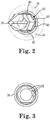
- proximal portion 52 of the interchangeable bit 34 has a generally hexagonal cross section with six discrete surfaces 60 that are complementary to interior surfaces 62 of socket 36 arranged in a hexagonal configuration. Articulation of the interchangeable bit 34 is typically perpendicular to one of the surfaces 62 of the socket 36.
- the socket 36 and proximal portions 52 can have other non-circular cross-sectional shapes, including triangular, square, pentagonal, star-shaped, curvilinear, and the like.
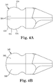
- Figure 4A illustrates an alternate interchangeable bit 34A where contoured portions 56A includes a plurality of facets 61A that approximate a curvilinear shape.
- Figure 4B illustrates another alternate interchangeable bit 34B in which the contoured portions 56B are curvilinear, without the flat portion.
- the radius of curvature of the contoured portions 56B can be uniform or non-uniform.
- the contoured portions 56B can have a variety of other shapes, such as for example, circular or elliptical.
- the contoured portions 56B correspond generally to the shape of a Torx driver, such as illustrated in U.S. Pat. Nos. 5,251,521 (Burda et al. ) and 5,408,905 (Mikic et al. ).
- Figure 6 illustrates angle of articulation 76 of the interchangeable bit 34 relative to the bit holder 20.
- the angle of articulation 76 is preferably between about 5 degrees to about 25 degrees.
- the angle of articulation 76 can be adjusted by a variety of mechanisms.
- the configuration of the present interchangeable bit 34 results in a pivot location 80 extremely close to the working end 40.
- the pivot location 80 is located within the proximal portion 52 of the interchangeable bit 34.
- the pivot location 80 may be a point.
- the pivot location 80 may be a sphere, an elliptical volume, or a variety of other shapes.
- the pivot location 80 is less than about 25.4 mm (about 1.0 inches) from the distal-most portion of the working end 40. In another embodiment, the pivot location 80 is less than about 10.16 mm (about 0.4 inches) from the distal-most portion of the working end 40. Consequently, wear on the working end 40 and vibration while driving fastener 64 are minimized.
- Figure 7 is a side sectional view of the bit holder of Figure 1 with the outer sleeve 42 slid forward in direction 88 to locked configuration 82 in accordance with an embodiment of the present disclosure.
- the socket 36 has a second depth 57, greater than the depth 53 illustrated in Figure 1 .
- inner surface 84 of the sleeve 42 near the distal end 74 engages with body portion 72 to retain the interchangeable bit 34 in axial alignment with longitudinal axis 63.
- Snap ring 46 engages with forward grooves 86 formed in the shaft 24 to retain the outer sleeve 42 in the locked configuration 82.
- Figure 8 illustrates the bit holder 20 driving fastener 64 with the outer sleeve 42 in the locked configuration 82.
- Figure 9 is a side sectional view of bit holder 100 in accordance with another embodiment of the present disclosure.
- the intermediate shaft 104 is located within the outer sleeve 106 to create first socket 108 and second socket 110 at opposite ends of the bit holder 100.
- the intermediate shaft 104 is preferably secured to the outer sleeve 106, such as by a compression fit, pin, swaging, or the like.
- the shank portion 102 and the interchangeable bit 112 can be coupled with either the first or second sockets 108, 110.
- the coupling of the shank portion 102, intermediate shaft 104 and outer sleeve 106, and interchangeable bit 112, can be magnetic, mechanical, frictional, and the like.
- first socket 108 has a depth 116 that permits interchangeable bit 112 to pivot off-angle, such as discussed in connection with Figure 1 .
- the first socket 108 corresponds to the unlocked configuration.
- Shank portion 102 couples with second socket 110 to act as an interface for a driver.
- the intermediate shaft 104 and the outer sleeve 106 can be flipped over so the interchangeable bit 112 is located in the second socket 110, with a depth 118 greater than the depth 116.
- the second socket 110 corresponds to the locked configuration.
- Body portion 120 of the interchangeable bit 112 is constrained by the inner walls 114 of the outer sleeve 106 to act as a straight-on bit, such as illustrated in Figure 7 .
- Shank portion 102 is coupled with the first socket 108 to interface with a driver 100.
Landscapes
- Engineering & Computer Science (AREA)
- Mechanical Engineering (AREA)
- Percussive Tools And Related Accessories (AREA)
- Surgical Instruments (AREA)
Claims (15)
- Support d'embout (20) comprenant :un arbre (24) ayant une extrémité proximale (22) adaptée pour être couplée à un dispositif d'entraînement ; etun manchon extérieur (42) entourant l'arbre (24) dans une configuration non verrouillée pour former une cavité (36) avec une section transversale non circulaire à proximité de l'extrémité distale (30) de l'arbre (24) ;au moins un embout interchangeable (34) comprenant une extrémité opérationnelle (40) et une partie proximale (52) avec une section transversale non circulaire complémentaire à la cavité (36), la partie proximale (52) comprenant une pluralité de parties sinueuses (56) qui permettent à l'embout interchangeable (34) de s'articuler dans la cavité (36), l'embout interchangeable (34) comprenant en outre un relief (70) situé entre l'extrémité opérationnelle (40) et la partie proximale (52) configuré pour permettre l'articulation de l'embout interchangeable (34) ; caractérisé parune extrémité distale (30) de l'arbre (24) couplée de manière aimantée à l'embout interchangeable (34) ;le relief (70) configuré de façon à entrer en prise avec l'extrémité distale (30) du manchon extérieur (42) pour limiter l'articulation par rapport à l'arbre (24) ; etune configuration verrouillée (82) pour le manchon extérieur (42) de sorte que l'extrémité distale (30) du manchon extérieur entre en prise avec une partie du corps (72) de l'embout interchangeable (34) pour retenir l'embout interchangeable (34) généralement aligné par rapport à un axe longitudinal (63) de l'arbre (24).
- Support d'embout (20) selon la revendication 1, comprenant un aimant (32) situé à proximité de l'extrémité distale (30) de l'arbre.
- Support d'embout (20) selon la revendication 1, comprenant un mécanisme de verrouillage adapté pour retenir le manchon extérieur (42) soit dans la configuration non verrouillée (50) soit dans la configuration verrouillée (82).
- Support d'embout (20) selon la revendication 1, comprenant :une bague élastique (46) interposée entre le manchon extérieur (42) et l'arbre (24) ;un premier ensemble de rainures (48A, 48B) sur l'arbre (24) adapté pour entrer en prise avec la bague élastique (46) quand le manchon extérieur (42) se trouve dans la configuration non verrouillée (50) ; etun second ensemble de rainures (86) sur l'arbre (24) adapté pour entrer en prise avec la bague élastique (46) quand le manchon extérieur (42) se trouve dans la configuration verrouillée (82).
- Support d'embout (20) selon la revendication 1, comprenant une partie plate sur la partie proximale (52) de l'embout interchangeable (34) et une partie plate correspondante sur l'extrémité distale (30) de l'arbre (24) qui coopèrent de façon à retenir l'embout interchangeable (34) généralement aligné par rapport à un axe longitudinal (63) de l'arbre (24) quand le manchon extérieur (42) est dans la configuration non verrouillée (50).
- Support d'embout (20) selon la revendication 1, dans lequel les parties sinueuses (56) de l'embout interchangeable (34) comprennent une pluralité de facettes (61A).
- Support d'embout (20) selon la revendication 1, dans lequel la partie proximale (52) de l'embout interchangeable (34) comprend une section transversale hexagonale et la cavité (36) comprend une pluralité de surfaces (62) agencée dans une configuration hexagonale complémentaire, l'embout interchangeable (34) s'articulant principalement dans un plan perpendiculaire à une surface parmi la pluralité des surfaces (62).
- Support d'embout (20) selon la revendication 1, dans lequel un emplacement du manchon extérieur (42) le long de l'arbre (24) détermine un angle maximum d'articulation (76) par rapport à l'axe longitudinal (63).
- Support d'embout (20) selon la revendication 1, dans lequel le manchon extérieur (42) comprend une pluralité de configurations non verrouillées (50).
- Support d'embout (20) selon la revendication 1, dans lequel un angle maximum d'articulation (76) pour l'embout interchangeable (34) est d'environ 5 degrés à environ 25 degrés.
- Support d'embout (20) selon la revendication 1, dans lequel un angle minimum d'articulation (76) pour l'embout interchangeable (34) est au moins d'environ 5 degrés.
- Support d'embout (20) selon la revendication 1, dans lequel un emplacement de pivot (80) s'étend à travers l'embout interchangeable (34) perpendiculairement à l'axe longitudinal (63).
- Support d'embout (20) selon la revendication 1, dans lequel un emplacement de pivot (80) de l'embout interchangeable (34) par rapport à la cavité (36) est inférieur à environ 25,4 mm (environ 1,0 pouce) à partir d'une partie la plus distale de l'extrémité opérationnelle (40).
- Support d'embout (20) selon la revendication 1, dans lequel un emplacement de pivot (80) de l'embout interchangeable (34) par rapport à la cavité (36) est inférieur à environ 10,16 mm (environ 0,4 pouce) à partir d'une partie la plus distale de l'extrémité opérationnelle (40) .
- Support d'embout (100), comprenant :un manchon extérieur (106) fixé à un arbre (104) de façon à former une première cavité (108) avec une première profondeur (116) et une seconde cavité (110) avec une seconde profondeur (118) supérieure à la première profondeur (116), à des extrémités opposées du manchon extérieur (106), les première et seconde cavités (108, 110) comprennent chacune une section transversale non circulaire ;un pied (102) ayant une section transversale non circulaire complémentaire à la première et seconde cavités (108, 110) ; etau moins un embout interchangeable (112) comprenant une extrémité opérationnelle et une partie proximale avec une section transversale non circulaire complémentaire à la première et seconde cavités (108, 110), la partie proximale comprenant une pluralité de parties sinueuses qui permettent à l'embout interchangeable (112) de s'articuler dans la première cavité (108), l'embout interchangeable (112) comprenant en outre un relief situé entre l'extrémité opérationnelle et la partie proximale, configuré pour entrer en prise avec une extrémité distale du manchon extérieur (106) pour limiter l'articulation par rapport à l'arbre (104), le manchon extérieur (106) à la seconde cavité (110) entrant en prise avec une partie de corps (120) de l'embout interchangeable (112) pour retenir l'embout interchangeable (112) généralement aligné par rapport à un axe longitudinal de l'arbre (104).
Applications Claiming Priority (2)
| Application Number | Priority Date | Filing Date | Title |
|---|---|---|---|
| US12/760,845 US8215208B2 (en) | 2010-04-15 | 2010-04-15 | Tool holder with pivoting bit |
| PCT/US2010/031601 WO2011129839A1 (fr) | 2010-04-15 | 2010-04-19 | Porte-outil avec embout pivotant |
Publications (2)
| Publication Number | Publication Date |
|---|---|
| EP2558246A1 EP2558246A1 (fr) | 2013-02-20 |
| EP2558246B1 true EP2558246B1 (fr) | 2017-11-29 |
Family
ID=43086330
Family Applications (1)
| Application Number | Title | Priority Date | Filing Date |
|---|---|---|---|
| EP10716177.0A Active EP2558246B1 (fr) | 2010-04-15 | 2010-04-19 | Porte-outil avec embout pivotant |
Country Status (3)
| Country | Link |
|---|---|
| US (1) | US8215208B2 (fr) |
| EP (1) | EP2558246B1 (fr) |
| WO (1) | WO2011129839A1 (fr) |
Families Citing this family (10)
| Publication number | Priority date | Publication date | Assignee | Title |
|---|---|---|---|---|
| US20120059385A1 (en) * | 2010-07-07 | 2012-03-08 | Orthohelix Surgical Designs, Inc. | Variable angle depth limited fastener driver and variable angle fixation system for use in orthopedic plates |
| US9080611B2 (en) * | 2010-12-01 | 2015-07-14 | Howmedica Osteonics Corp. | Drive tool having an angled connector |
| US20130019721A1 (en) * | 2011-07-18 | 2013-01-24 | Starogiannis Athanasios T | Tilting screw bit and screw bit holder |
| TWI473690B (zh) * | 2013-02-19 | 2015-02-21 | Kabo Tool Co | Can quickly change the grip angle of the wrench |
| US9364943B2 (en) * | 2013-12-10 | 2016-06-14 | Chih-Min Chang | Quick rotatable wrench |
| US9597093B2 (en) | 2014-06-10 | 2017-03-21 | Howmedica Osteonics Corp. | Temporarily fixable angled drill |
| TWI542447B (zh) * | 2014-08-27 | 2016-07-21 | Hou-Fei Hu | Ratchet wrench and its combination with the drive |
| US11179831B2 (en) * | 2018-07-11 | 2021-11-23 | Milwaukee Electric Tool Corporation | Lockable drive socket adapter |
| IT202000014869A1 (it) * | 2020-06-22 | 2021-12-22 | Nuova Ompi Srl | Apparato di formatura del cono di alloggiamento di un ago in una siringa, metodo di realizzazione del cono di alloggiamento di un ago in una siringa e relativa siringa |
| US20250042005A1 (en) * | 2023-08-01 | 2025-02-06 | Yi-Fu Chen | Multi-segment bendable joint |
Family Cites Families (20)
| Publication number | Priority date | Publication date | Assignee | Title |
|---|---|---|---|---|
| US2667194A (en) | 1950-05-24 | 1954-01-26 | Apex Machine & Tool Company | Composite bit screw driver |
| US2773529A (en) | 1954-12-29 | 1956-12-11 | Victor A Valenti | Hand tool with angularly adjustable bit |
| US4271731A (en) | 1979-09-07 | 1981-06-09 | Diane Suligoy | Pivot tip hand tool |
| US4436005A (en) * | 1982-03-10 | 1984-03-13 | Hanson Alan R | Rotary torque adapter |
| JPS6334080A (ja) | 1986-07-24 | 1988-02-13 | ダイヤ精工株式会社 | ラチエツトハンドル |
| US5042332A (en) | 1988-08-23 | 1991-08-27 | Qualicorp, Ltd. | Angularly displaced pin coupling |
| US5251521A (en) | 1992-01-31 | 1993-10-12 | Bondhus Corporation | TORX-compatible elliptical driver |
| US5370021A (en) * | 1993-05-13 | 1994-12-06 | Eight Co., Ltd. | Polygon headed wrench |
| US5408905A (en) | 1993-12-27 | 1995-04-25 | Snap-On Incorporated | Tiltable ball-type driver |
| US5738586A (en) * | 1994-09-09 | 1998-04-14 | Consolidated Devices Inc. | Semi-universal torque coupling |
| US5577426A (en) | 1994-11-08 | 1996-11-26 | Snap-On Technologies, Inc. | Magnetic bit holder and hand tool incorporating same |
| US6347564B1 (en) | 1998-09-28 | 2002-02-19 | Quintino Matthew Ciocca | Fastener-driving hand tool having an angularly displaceable bit retainer |
| DE20009358U1 (de) * | 2000-05-24 | 2000-08-10 | Wiha Werkzeuge Willi Hahn GmbH & Co. KG, 78136 Schonach | Aufnahmekopf für ein Werkzeug mit einer Schlitz- oder Mehrkantbetätigungsspitze |
| US6681662B2 (en) | 2002-03-01 | 2004-01-27 | Bondhus Corporation | Tool with fastener engaging member |
| US6729211B1 (en) * | 2002-12-09 | 2004-05-04 | The United States Of America As Represented By The Secretary Of The Navy | Ball socket driver bit |
| US20050235785A1 (en) | 2004-04-21 | 2005-10-27 | Chang Sheng-Ming | Multi-angle adjusting socket body and improved structure of its tools |
| US7278342B1 (en) | 2006-03-21 | 2007-10-09 | Sheng Ming Chang | Tool connecting device |
| US20080168868A1 (en) * | 2007-01-12 | 2008-07-17 | Min-Li Yang | Assistant connector for a tool |
| GB2445737A (en) | 2007-01-18 | 2008-07-23 | Hung Yu Tool Ind Co Ltd | Assistant connector for a tool |
| TW201103713A (en) * | 2009-07-27 | 2011-02-01 | Cai-Qing Chen | Tool with bending angle |
-
2010
- 2010-04-15 US US12/760,845 patent/US8215208B2/en active Active
- 2010-04-19 WO PCT/US2010/031601 patent/WO2011129839A1/fr not_active Ceased
- 2010-04-19 EP EP10716177.0A patent/EP2558246B1/fr active Active
Also Published As
| Publication number | Publication date |
|---|---|
| US8215208B2 (en) | 2012-07-10 |
| WO2011129839A1 (fr) | 2011-10-20 |
| EP2558246A1 (fr) | 2013-02-20 |
| US20110252928A1 (en) | 2011-10-20 |
Similar Documents
| Publication | Publication Date | Title |
|---|---|---|
| US8215208B2 (en) | Tool holder with pivoting bit | |
| US7278342B1 (en) | Tool connecting device | |
| US7481136B2 (en) | Tool device for driving various tool members | |
| US7430943B2 (en) | Driving tool having rotatable coupling | |
| US7597031B2 (en) | Driving tool having rotatable coupling | |
| US7363839B2 (en) | Driving tool having rotatable coupling | |
| US7018298B1 (en) | Pivotal driving tool assembly | |
| EP2393634B1 (fr) | Tournevis | |
| CN103582543B (zh) | 可拆除管状抓持元件 | |
| US20100107828A1 (en) | Adjustable Handle System for Fastening Tools That Drive Threaded Fasteners | |
| US5943922A (en) | Chuck for threaded fasteners | |
| US20090145268A1 (en) | Hybrid low profile and standard ratchet system | |
| US20060260446A1 (en) | Tool connecting device | |
| EP1902816A2 (fr) | Embout de tournevis pour vis autoforeuse | |
| US11666344B2 (en) | Multiple connection drive shaft | |
| US20110017029A1 (en) | Hand Tool | |
| EP1955667B1 (fr) | Tournevis global de rétention de vis et de clous | |
| KR20010075008A (ko) | 드라이버 비트 및 드라이버 | |
| EP2693956A1 (fr) | Configuration de queue de fraise de coupe | |
| US20070144313A1 (en) | Tool connecting device | |
| US7228767B2 (en) | Tool connecting device | |
| US20110143316A1 (en) | Dental implant driver and carrier removal system | |
| US20150020652A1 (en) | Tool Bit Having Improved Removability | |
| US6363820B1 (en) | Hand tool for driving a fastener about an axis | |
| US11433512B1 (en) | Angle driven access tool |
Legal Events
| Date | Code | Title | Description |
|---|---|---|---|
| PUAI | Public reference made under article 153(3) epc to a published international application that has entered the european phase |
Free format text: ORIGINAL CODE: 0009012 |
|
| 17P | Request for examination filed |
Effective date: 20120905 |
|
| AK | Designated contracting states |
Kind code of ref document: A1 Designated state(s): AT BE BG CH CY CZ DE DK EE ES FI FR GB GR HR HU IE IS IT LI LT LU LV MC MK MT NL NO PL PT RO SE SI SK SM TR |
|
| RIN1 | Information on inventor provided before grant (corrected) |
Inventor name: BLACKSTON, MIKE Inventor name: PETROSKE, MARK |
|
| DAX | Request for extension of the european patent (deleted) | ||
| 17Q | First examination report despatched |
Effective date: 20160901 |
|
| GRAP | Despatch of communication of intention to grant a patent |
Free format text: ORIGINAL CODE: EPIDOSNIGR1 |
|
| INTG | Intention to grant announced |
Effective date: 20170511 |
|
| GRAS | Grant fee paid |
Free format text: ORIGINAL CODE: EPIDOSNIGR3 |
|
| GRAA | (expected) grant |
Free format text: ORIGINAL CODE: 0009210 |
|
| AK | Designated contracting states |
Kind code of ref document: B1 Designated state(s): AT BE BG CH CY CZ DE DK EE ES FI FR GB GR HR HU IE IS IT LI LT LU LV MC MK MT NL NO PL PT RO SE SI SK SM TR |
|
| REG | Reference to a national code |
Ref country code: CH Ref legal event code: EP |
|
| REG | Reference to a national code |
Ref country code: AT Ref legal event code: REF Ref document number: 949955 Country of ref document: AT Kind code of ref document: T Effective date: 20171215 |
|
| REG | Reference to a national code |
Ref country code: IE Ref legal event code: FG4D |
|
| REG | Reference to a national code |
Ref country code: DE Ref legal event code: R096 Ref document number: 602010047011 Country of ref document: DE |
|
| REG | Reference to a national code |
Ref country code: NL Ref legal event code: MP Effective date: 20171129 |
|
| REG | Reference to a national code |
Ref country code: LT Ref legal event code: MG4D |
|
| REG | Reference to a national code |
Ref country code: AT Ref legal event code: MK05 Ref document number: 949955 Country of ref document: AT Kind code of ref document: T Effective date: 20171129 |
|
| PG25 | Lapsed in a contracting state [announced via postgrant information from national office to epo] |
Ref country code: NO Free format text: LAPSE BECAUSE OF FAILURE TO SUBMIT A TRANSLATION OF THE DESCRIPTION OR TO PAY THE FEE WITHIN THE PRESCRIBED TIME-LIMIT Effective date: 20180228 Ref country code: FI Free format text: LAPSE BECAUSE OF FAILURE TO SUBMIT A TRANSLATION OF THE DESCRIPTION OR TO PAY THE FEE WITHIN THE PRESCRIBED TIME-LIMIT Effective date: 20171129 Ref country code: SE Free format text: LAPSE BECAUSE OF FAILURE TO SUBMIT A TRANSLATION OF THE DESCRIPTION OR TO PAY THE FEE WITHIN THE PRESCRIBED TIME-LIMIT Effective date: 20171129 Ref country code: LT Free format text: LAPSE BECAUSE OF FAILURE TO SUBMIT A TRANSLATION OF THE DESCRIPTION OR TO PAY THE FEE WITHIN THE PRESCRIBED TIME-LIMIT Effective date: 20171129 Ref country code: ES Free format text: LAPSE BECAUSE OF FAILURE TO SUBMIT A TRANSLATION OF THE DESCRIPTION OR TO PAY THE FEE WITHIN THE PRESCRIBED TIME-LIMIT Effective date: 20171129 |
|
| PG25 | Lapsed in a contracting state [announced via postgrant information from national office to epo] |
Ref country code: HR Free format text: LAPSE BECAUSE OF FAILURE TO SUBMIT A TRANSLATION OF THE DESCRIPTION OR TO PAY THE FEE WITHIN THE PRESCRIBED TIME-LIMIT Effective date: 20171129 Ref country code: AT Free format text: LAPSE BECAUSE OF FAILURE TO SUBMIT A TRANSLATION OF THE DESCRIPTION OR TO PAY THE FEE WITHIN THE PRESCRIBED TIME-LIMIT Effective date: 20171129 Ref country code: LV Free format text: LAPSE BECAUSE OF FAILURE TO SUBMIT A TRANSLATION OF THE DESCRIPTION OR TO PAY THE FEE WITHIN THE PRESCRIBED TIME-LIMIT Effective date: 20171129 Ref country code: GR Free format text: LAPSE BECAUSE OF FAILURE TO SUBMIT A TRANSLATION OF THE DESCRIPTION OR TO PAY THE FEE WITHIN THE PRESCRIBED TIME-LIMIT Effective date: 20180301 Ref country code: BG Free format text: LAPSE BECAUSE OF FAILURE TO SUBMIT A TRANSLATION OF THE DESCRIPTION OR TO PAY THE FEE WITHIN THE PRESCRIBED TIME-LIMIT Effective date: 20180228 |
|
| PG25 | Lapsed in a contracting state [announced via postgrant information from national office to epo] |
Ref country code: NL Free format text: LAPSE BECAUSE OF FAILURE TO SUBMIT A TRANSLATION OF THE DESCRIPTION OR TO PAY THE FEE WITHIN THE PRESCRIBED TIME-LIMIT Effective date: 20171129 |
|
| PG25 | Lapsed in a contracting state [announced via postgrant information from national office to epo] |
Ref country code: CZ Free format text: LAPSE BECAUSE OF FAILURE TO SUBMIT A TRANSLATION OF THE DESCRIPTION OR TO PAY THE FEE WITHIN THE PRESCRIBED TIME-LIMIT Effective date: 20171129 Ref country code: EE Free format text: LAPSE BECAUSE OF FAILURE TO SUBMIT A TRANSLATION OF THE DESCRIPTION OR TO PAY THE FEE WITHIN THE PRESCRIBED TIME-LIMIT Effective date: 20171129 Ref country code: CY Free format text: LAPSE BECAUSE OF FAILURE TO SUBMIT A TRANSLATION OF THE DESCRIPTION OR TO PAY THE FEE WITHIN THE PRESCRIBED TIME-LIMIT Effective date: 20171129 Ref country code: DK Free format text: LAPSE BECAUSE OF FAILURE TO SUBMIT A TRANSLATION OF THE DESCRIPTION OR TO PAY THE FEE WITHIN THE PRESCRIBED TIME-LIMIT Effective date: 20171129 Ref country code: SK Free format text: LAPSE BECAUSE OF FAILURE TO SUBMIT A TRANSLATION OF THE DESCRIPTION OR TO PAY THE FEE WITHIN THE PRESCRIBED TIME-LIMIT Effective date: 20171129 |
|
| REG | Reference to a national code |
Ref country code: DE Ref legal event code: R097 Ref document number: 602010047011 Country of ref document: DE |
|
| PG25 | Lapsed in a contracting state [announced via postgrant information from national office to epo] |
Ref country code: SM Free format text: LAPSE BECAUSE OF FAILURE TO SUBMIT A TRANSLATION OF THE DESCRIPTION OR TO PAY THE FEE WITHIN THE PRESCRIBED TIME-LIMIT Effective date: 20171129 Ref country code: PL Free format text: LAPSE BECAUSE OF FAILURE TO SUBMIT A TRANSLATION OF THE DESCRIPTION OR TO PAY THE FEE WITHIN THE PRESCRIBED TIME-LIMIT Effective date: 20171129 Ref country code: IT Free format text: LAPSE BECAUSE OF FAILURE TO SUBMIT A TRANSLATION OF THE DESCRIPTION OR TO PAY THE FEE WITHIN THE PRESCRIBED TIME-LIMIT Effective date: 20171129 Ref country code: RO Free format text: LAPSE BECAUSE OF FAILURE TO SUBMIT A TRANSLATION OF THE DESCRIPTION OR TO PAY THE FEE WITHIN THE PRESCRIBED TIME-LIMIT Effective date: 20171129 |
|
| PLBE | No opposition filed within time limit |
Free format text: ORIGINAL CODE: 0009261 |
|
| STAA | Information on the status of an ep patent application or granted ep patent |
Free format text: STATUS: NO OPPOSITION FILED WITHIN TIME LIMIT |
|
| 26N | No opposition filed |
Effective date: 20180830 |
|
| PG25 | Lapsed in a contracting state [announced via postgrant information from national office to epo] |
Ref country code: SI Free format text: LAPSE BECAUSE OF FAILURE TO SUBMIT A TRANSLATION OF THE DESCRIPTION OR TO PAY THE FEE WITHIN THE PRESCRIBED TIME-LIMIT Effective date: 20171129 Ref country code: MC Free format text: LAPSE BECAUSE OF FAILURE TO SUBMIT A TRANSLATION OF THE DESCRIPTION OR TO PAY THE FEE WITHIN THE PRESCRIBED TIME-LIMIT Effective date: 20171129 |
|
| REG | Reference to a national code |
Ref country code: CH Ref legal event code: PL |
|
| REG | Reference to a national code |
Ref country code: BE Ref legal event code: MM Effective date: 20180430 |
|
| REG | Reference to a national code |
Ref country code: IE Ref legal event code: MM4A |
|
| PG25 | Lapsed in a contracting state [announced via postgrant information from national office to epo] |
Ref country code: LU Free format text: LAPSE BECAUSE OF NON-PAYMENT OF DUE FEES Effective date: 20180419 |
|
| PG25 | Lapsed in a contracting state [announced via postgrant information from national office to epo] |
Ref country code: BE Free format text: LAPSE BECAUSE OF NON-PAYMENT OF DUE FEES Effective date: 20180430 Ref country code: LI Free format text: LAPSE BECAUSE OF NON-PAYMENT OF DUE FEES Effective date: 20180430 Ref country code: CH Free format text: LAPSE BECAUSE OF NON-PAYMENT OF DUE FEES Effective date: 20180430 |
|
| PG25 | Lapsed in a contracting state [announced via postgrant information from national office to epo] |
Ref country code: FR Free format text: LAPSE BECAUSE OF NON-PAYMENT OF DUE FEES Effective date: 20180430 Ref country code: IE Free format text: LAPSE BECAUSE OF NON-PAYMENT OF DUE FEES Effective date: 20180419 |
|
| PG25 | Lapsed in a contracting state [announced via postgrant information from national office to epo] |
Ref country code: MT Free format text: LAPSE BECAUSE OF NON-PAYMENT OF DUE FEES Effective date: 20180419 |
|
| PG25 | Lapsed in a contracting state [announced via postgrant information from national office to epo] |
Ref country code: TR Free format text: LAPSE BECAUSE OF FAILURE TO SUBMIT A TRANSLATION OF THE DESCRIPTION OR TO PAY THE FEE WITHIN THE PRESCRIBED TIME-LIMIT Effective date: 20171129 |
|
| PG25 | Lapsed in a contracting state [announced via postgrant information from national office to epo] |
Ref country code: HU Free format text: LAPSE BECAUSE OF FAILURE TO SUBMIT A TRANSLATION OF THE DESCRIPTION OR TO PAY THE FEE WITHIN THE PRESCRIBED TIME-LIMIT; INVALID AB INITIO Effective date: 20100419 Ref country code: PT Free format text: LAPSE BECAUSE OF FAILURE TO SUBMIT A TRANSLATION OF THE DESCRIPTION OR TO PAY THE FEE WITHIN THE PRESCRIBED TIME-LIMIT Effective date: 20171129 |
|
| PG25 | Lapsed in a contracting state [announced via postgrant information from national office to epo] |
Ref country code: MK Free format text: LAPSE BECAUSE OF NON-PAYMENT OF DUE FEES Effective date: 20171129 |
|
| PG25 | Lapsed in a contracting state [announced via postgrant information from national office to epo] |
Ref country code: IS Free format text: LAPSE BECAUSE OF FAILURE TO SUBMIT A TRANSLATION OF THE DESCRIPTION OR TO PAY THE FEE WITHIN THE PRESCRIBED TIME-LIMIT Effective date: 20180329 |
|
| PGFP | Annual fee paid to national office [announced via postgrant information from national office to epo] |
Ref country code: DE Payment date: 20250319 Year of fee payment: 16 |
|
| PGFP | Annual fee paid to national office [announced via postgrant information from national office to epo] |
Ref country code: GB Payment date: 20260303 Year of fee payment: 17 |