EP2558320B1 - System und verfahren zum steuern einer drehmomentkupplung entsprechend mehrerer betriebsarten - Google Patents
System und verfahren zum steuern einer drehmomentkupplung entsprechend mehrerer betriebsarten Download PDFInfo
- Publication number
- EP2558320B1 EP2558320B1 EP11731006.0A EP11731006A EP2558320B1 EP 2558320 B1 EP2558320 B1 EP 2558320B1 EP 11731006 A EP11731006 A EP 11731006A EP 2558320 B1 EP2558320 B1 EP 2558320B1
- Authority
- EP
- European Patent Office
- Prior art keywords
- torque transfer
- wheel
- control
- mode
- signal
- Prior art date
- Legal status (The legal status is an assumption and is not a legal conclusion. Google has not performed a legal analysis and makes no representation as to the accuracy of the status listed.)
- Not-in-force
Links
Images


Classifications
-
- B—PERFORMING OPERATIONS; TRANSPORTING
- B60—VEHICLES IN GENERAL
- B60K—ARRANGEMENT OR MOUNTING OF PROPULSION UNITS OR OF TRANSMISSIONS IN VEHICLES; ARRANGEMENT OR MOUNTING OF PLURAL DIVERSE PRIME-MOVERS IN VEHICLES; AUXILIARY DRIVES FOR VEHICLES; INSTRUMENTATION OR DASHBOARDS FOR VEHICLES; ARRANGEMENTS IN CONNECTION WITH COOLING, AIR INTAKE, GAS EXHAUST OR FUEL SUPPLY OF PROPULSION UNITS IN VEHICLES
- B60K17/00—Arrangement or mounting of transmissions in vehicles
- B60K17/34—Arrangement or mounting of transmissions in vehicles for driving both front and rear wheels, e.g. four wheel drive vehicles
- B60K17/344—Arrangement or mounting of transmissions in vehicles for driving both front and rear wheels, e.g. four wheel drive vehicles having a transfer gear
- B60K17/346—Arrangement or mounting of transmissions in vehicles for driving both front and rear wheels, e.g. four wheel drive vehicles having a transfer gear the transfer gear being a differential gear
- B60K17/3462—Arrangement or mounting of transmissions in vehicles for driving both front and rear wheels, e.g. four wheel drive vehicles having a transfer gear the transfer gear being a differential gear with means for changing distribution of torque between front and rear wheels
- B60K17/3465—Arrangement or mounting of transmissions in vehicles for driving both front and rear wheels, e.g. four wheel drive vehicles having a transfer gear the transfer gear being a differential gear with means for changing distribution of torque between front and rear wheels self-actuated means, e.g. differential locked automatically by difference of speed
-
- B—PERFORMING OPERATIONS; TRANSPORTING
- B60—VEHICLES IN GENERAL
- B60K—ARRANGEMENT OR MOUNTING OF PROPULSION UNITS OR OF TRANSMISSIONS IN VEHICLES; ARRANGEMENT OR MOUNTING OF PLURAL DIVERSE PRIME-MOVERS IN VEHICLES; AUXILIARY DRIVES FOR VEHICLES; INSTRUMENTATION OR DASHBOARDS FOR VEHICLES; ARRANGEMENTS IN CONNECTION WITH COOLING, AIR INTAKE, GAS EXHAUST OR FUEL SUPPLY OF PROPULSION UNITS IN VEHICLES
- B60K17/00—Arrangement or mounting of transmissions in vehicles
- B60K17/34—Arrangement or mounting of transmissions in vehicles for driving both front and rear wheels, e.g. four wheel drive vehicles
- B60K17/344—Arrangement or mounting of transmissions in vehicles for driving both front and rear wheels, e.g. four wheel drive vehicles having a transfer gear
- B60K17/346—Arrangement or mounting of transmissions in vehicles for driving both front and rear wheels, e.g. four wheel drive vehicles having a transfer gear the transfer gear being a differential gear
- B60K17/3462—Arrangement or mounting of transmissions in vehicles for driving both front and rear wheels, e.g. four wheel drive vehicles having a transfer gear the transfer gear being a differential gear with means for changing distribution of torque between front and rear wheels
-
- B—PERFORMING OPERATIONS; TRANSPORTING
- B60—VEHICLES IN GENERAL
- B60K—ARRANGEMENT OR MOUNTING OF PROPULSION UNITS OR OF TRANSMISSIONS IN VEHICLES; ARRANGEMENT OR MOUNTING OF PLURAL DIVERSE PRIME-MOVERS IN VEHICLES; AUXILIARY DRIVES FOR VEHICLES; INSTRUMENTATION OR DASHBOARDS FOR VEHICLES; ARRANGEMENTS IN CONNECTION WITH COOLING, AIR INTAKE, GAS EXHAUST OR FUEL SUPPLY OF PROPULSION UNITS IN VEHICLES
- B60K17/00—Arrangement or mounting of transmissions in vehicles
- B60K17/34—Arrangement or mounting of transmissions in vehicles for driving both front and rear wheels, e.g. four wheel drive vehicles
- B60K17/348—Arrangement or mounting of transmissions in vehicles for driving both front and rear wheels, e.g. four wheel drive vehicles having differential means for driving one set of wheels, e.g. the front, at one speed and the other set, e.g. the rear, at a different speed
- B60K17/35—Arrangement or mounting of transmissions in vehicles for driving both front and rear wheels, e.g. four wheel drive vehicles having differential means for driving one set of wheels, e.g. the front, at one speed and the other set, e.g. the rear, at a different speed including arrangements for suppressing or influencing the power transfer, e.g. viscous clutches
- B60K17/352—Arrangement or mounting of transmissions in vehicles for driving both front and rear wheels, e.g. four wheel drive vehicles having differential means for driving one set of wheels, e.g. the front, at one speed and the other set, e.g. the rear, at a different speed including arrangements for suppressing or influencing the power transfer, e.g. viscous clutches manually operated
-
- B—PERFORMING OPERATIONS; TRANSPORTING
- B60—VEHICLES IN GENERAL
- B60K—ARRANGEMENT OR MOUNTING OF PROPULSION UNITS OR OF TRANSMISSIONS IN VEHICLES; ARRANGEMENT OR MOUNTING OF PLURAL DIVERSE PRIME-MOVERS IN VEHICLES; AUXILIARY DRIVES FOR VEHICLES; INSTRUMENTATION OR DASHBOARDS FOR VEHICLES; ARRANGEMENTS IN CONNECTION WITH COOLING, AIR INTAKE, GAS EXHAUST OR FUEL SUPPLY OF PROPULSION UNITS IN VEHICLES
- B60K23/00—Arrangement or mounting of control devices for vehicle transmissions, or parts thereof, not otherwise provided for
- B60K23/08—Arrangement or mounting of control devices for vehicle transmissions, or parts thereof, not otherwise provided for for changing number of driven wheels, for switching from driving one axle to driving two or more axles
- B60K23/0808—Arrangement or mounting of control devices for vehicle transmissions, or parts thereof, not otherwise provided for for changing number of driven wheels, for switching from driving one axle to driving two or more axles for varying torque distribution between driven axles, e.g. by transfer clutch
-
- B—PERFORMING OPERATIONS; TRANSPORTING
- B60—VEHICLES IN GENERAL
- B60T—VEHICLE BRAKE CONTROL SYSTEMS OR PARTS THEREOF; BRAKE CONTROL SYSTEMS OR PARTS THEREOF, IN GENERAL; ARRANGEMENT OF BRAKING ELEMENTS ON VEHICLES IN GENERAL; PORTABLE DEVICES FOR PREVENTING UNWANTED MOVEMENT OF VEHICLES; VEHICLE MODIFICATIONS TO FACILITATE COOLING OF BRAKES
- B60T8/00—Arrangements for adjusting wheel-braking force to meet varying vehicular or ground-surface conditions, e.g. limiting or varying distribution of braking force
- B60T8/17—Using electrical or electronic regulation means to control braking
- B60T8/176—Brake regulation specially adapted to prevent excessive wheel slip during vehicle deceleration, e.g. ABS
- B60T8/1769—Brake regulation specially adapted to prevent excessive wheel slip during vehicle deceleration, e.g. ABS specially adapted for vehicles having more than one driven axle, e.g. four-wheel drive vehicles
-
- B—PERFORMING OPERATIONS; TRANSPORTING
- B60—VEHICLES IN GENERAL
- B60W—CONJOINT CONTROL OF VEHICLE SUB-UNITS OF DIFFERENT TYPE OR DIFFERENT FUNCTION; CONTROL SYSTEMS SPECIALLY ADAPTED FOR HYBRID VEHICLES; ROAD VEHICLE DRIVE CONTROL SYSTEMS FOR PURPOSES NOT RELATED TO THE CONTROL OF A PARTICULAR SUB-UNIT
- B60W10/00—Conjoint control of vehicle sub-units of different type or different function
- B60W10/02—Conjoint control of vehicle sub-units of different type or different function including control of driveline clutches
-
- B—PERFORMING OPERATIONS; TRANSPORTING
- B60—VEHICLES IN GENERAL
- B60W—CONJOINT CONTROL OF VEHICLE SUB-UNITS OF DIFFERENT TYPE OR DIFFERENT FUNCTION; CONTROL SYSTEMS SPECIALLY ADAPTED FOR HYBRID VEHICLES; ROAD VEHICLE DRIVE CONTROL SYSTEMS FOR PURPOSES NOT RELATED TO THE CONTROL OF A PARTICULAR SUB-UNIT
- B60W10/00—Conjoint control of vehicle sub-units of different type or different function
- B60W10/18—Conjoint control of vehicle sub-units of different type or different function including control of braking systems
-
- B—PERFORMING OPERATIONS; TRANSPORTING
- B60—VEHICLES IN GENERAL
- B60W—CONJOINT CONTROL OF VEHICLE SUB-UNITS OF DIFFERENT TYPE OR DIFFERENT FUNCTION; CONTROL SYSTEMS SPECIALLY ADAPTED FOR HYBRID VEHICLES; ROAD VEHICLE DRIVE CONTROL SYSTEMS FOR PURPOSES NOT RELATED TO THE CONTROL OF A PARTICULAR SUB-UNIT
- B60W30/00—Purposes of road vehicle drive control systems not related to the control of a particular sub-unit, e.g. of systems using conjoint control of vehicle sub-units
- B60W30/18—Propelling the vehicle
- B60W30/18172—Preventing, or responsive to skidding of wheels
-
- B—PERFORMING OPERATIONS; TRANSPORTING
- B60—VEHICLES IN GENERAL
- B60T—VEHICLE BRAKE CONTROL SYSTEMS OR PARTS THEREOF; BRAKE CONTROL SYSTEMS OR PARTS THEREOF, IN GENERAL; ARRANGEMENT OF BRAKING ELEMENTS ON VEHICLES IN GENERAL; PORTABLE DEVICES FOR PREVENTING UNWANTED MOVEMENT OF VEHICLES; VEHICLE MODIFICATIONS TO FACILITATE COOLING OF BRAKES
- B60T2270/00—Further aspects of brake control systems not otherwise provided for
- B60T2270/10—ABS control systems
- B60T2270/12—ABS control systems for all-wheel drive vehicles
-
- B—PERFORMING OPERATIONS; TRANSPORTING
- B60—VEHICLES IN GENERAL
- B60W—CONJOINT CONTROL OF VEHICLE SUB-UNITS OF DIFFERENT TYPE OR DIFFERENT FUNCTION; CONTROL SYSTEMS SPECIALLY ADAPTED FOR HYBRID VEHICLES; ROAD VEHICLE DRIVE CONTROL SYSTEMS FOR PURPOSES NOT RELATED TO THE CONTROL OF A PARTICULAR SUB-UNIT
- B60W2720/00—Output or target parameters relating to overall vehicle dynamics
- B60W2720/40—Torque distribution
- B60W2720/403—Torque distribution between front and rear axle
Definitions
- the present invention is in the technical field of transmissions for motor vehicles and more particularly in the field of control of motor vehicle transmissions.
- Motor vehicle transmissions historically include two-wheel drive transmissions for the majority of four-wheel drive vehicles and transmissions for off-road vehicles.
- four-wheel drive vehicles have high fuel consumption and poor road performance.
- the US patent US 5752211 discloses a control method that improves fuel consumption by determining an offset value. This offset value varies as the cube of the speed, and is subtracted from the torque distribution command. This control method makes it possible to improve the difference between the speed of the front axle and the speed of the rear axle during the phases of quasi-static rolling.
- the European patent application EP 1188597 discloses a method of distributing the torque between the front and rear trains according to a tire diameter variation detection due to wear or change.
- the European patent application EP 1275549 describes a method of distributing torque between the front and rear trains as a function of different signals such as wheel speeds and throttle pedal position. This method improves the performance of the vehicle by improving the ratio between the speed of the front axle and the speed of the rear axle but does not describe a method of determining the setpoint.
- the Japanese patent JP 10119598 describes a control method applied to a four-wheel drive vehicle, the main drive wheels of which are located on the rear axle.
- the system is able to transfer a portion of the torque of the rear drive wheels on the front wheels. This transfer is activated when the rear drive wheels slip.
- the US patent US 5247443 describes a method of distributing the torque between the front and rear trains as a function of the difference between the speeds of rotation of the front and rear trains.
- the method also modifies the detection threshold of a slip if a braking is engaged. This method improves the performance of the vehicle by optimizing the sliding but does not take into account the intensity of the braking in the determination of the distribution of the torque.
- the European patent application EP 1627763 describes a method taking into account the braking in the distribution of the torque between the front and rear trains.
- the object of the present invention is a method of controlling a torque transfer actuator adapted to take into account the operating conditions of the anti-lock system of the wheels during braking and the torque transfer system, as well as the braking level.
- a control system of a torque transfer actuator adapted to take into account the operating conditions of the anti-lock system of the wheels during braking and the torque transfer system.
- a control system of a torque transfer actuator for a four-wheel drive motor vehicle comprises determining means and an anti-lock system of the wheels.
- the control system comprises an anti-lock wheel control means and a torque transfer actuator control means adapted to cooperate to transmit the torque transfer control to the transfer transfer actuator. couple.
- the anti-lock wheel control means is able to determine a wheel anti-lock control as a function of the torque transfer command received from the control means of the torque transfer actuator, the control means of the torque transfer actuator being adapted to determine a torque transfer control according to the anti-lock control of the wheels.
- the control system allows the anti-lock braking and torque transfer to cooperate, which makes it possible to develop a torque transfer setpoint which is not erroneously determined because of an unjustified triggering of the anti-blocking of the wheels. wheels.
- the control system may comprise a manual control member connected to the control means of the torque transfer actuator, and the manual control member can take several positions, and be manipulated by the driver of the vehicle, and may be able to emit a signal according to the position chosen by the driver.
- the control system comprises a means for determining the driving situation, able to transmit a control signal to the controlled switch based on the signals received from the determination means and the received torque transfer command.
- the control means of the torque transfer actuator and a controlled switch adapted to emit a detection signal of a wheel lock.
- the control system further comprises a first wheel lock detection means and a second wheel lock detection means each connected to a terminal of the controlled switch, and each adapted to determine the existence of a wheel lock when braking according to the rotational speed signals of each wheel received from the determination means.
- the control system comprises a means of estimating the braking level being able to emit a signal as a function of the pressure signal in the braking circuit received from the determination means, an AND-type logic operator being able to issue an anti-lock control of the wheels relating to the operating state of the anti-lock wheel control means, as a function of the signals received from the controlled switch and the level estimation means braking.
- the control system comprises a means for determining the activity of the anti-lock system of the wheels capable of determining a trip control signal of the anti-lock system of the wheels as a function of the signals received from the determination means and the control of the anti-lock system. anti-lock wheel received from the anti-lock control means of the wheels.
- the anti-lock control of the wheels depends on the torque transfer control, including the driver's driving mode request, the state of the torque transfer system and the active driving mode in the torque transfer system. .
- a detection signal of a wheel lock is determined according to at least two wheel lock detection modes, and according to the vehicle speed and torque transfer control, including the request. fashion conduct of the driver, state of the torque transfer system, active driving mode in the torque transfer system.
- a first wheel lock detection mode may be selected if the driver's driving mode request is not off-road, or if the active mode of driving in the torque transfer system is not all terrain, or if the vehicle speed is greater than a threshold value or if a failure of the torque transfer actuator other than a thermal failure is detected.
- a second wheel lock detection mode can be selected if the first wheel lock detection mode has not been activated, the second wheel lock detection mode has a lower detection sensitivity than the detection sensitivity the first mode of detecting wheel lock.
- a braking detection signal is determined if the pressure of the braking system is greater than a threshold value, the anti-lock control of the wheels is determined as a function of the detection signal of a wheel lock and of the brake detection signal, and a release control signal of the anti-lock braking system is determined according to the vehicle speed, the anti-lock control of the wheels, the driver's driving mode request and a request signal of braking.
- a torque transfer setpoint in two-wheel drive mode a torque transfer setpoint in four-wheel drive mode, an off-road four-wheel drive torque transfer setpoint, and a torque transfer setpoint in four-wheel-drive mode.
- braking a torque transfer setpoint can be chosen according to the speed of the vehicle, the driver's driving mode request, the depressing of the brake pedal, the activation of the parking brake, and a anti-lock system trip control signal, and the torque transfer command can be issued according to the selected torque transfer setpoint.
- the control system illustrated comprises determination means 1, an anti-lock wheel control means 2, a control means 3 of the torque transfer actuator, a manual control member 4 and a transfer actuator 5. couple.
- the determination means 1 are connected to the anti-lock control means 2 of the wheels of the vehicle via the connection 6 and to the control means 3 of the torque transfer actuator via the connection 7.
- the determining means 1 may comprise physical sensors or calculation means able to determine the quantities required from a model and data provided by other sensors.
- the anti-lock wheel control means 2 is connected at the output to the control means 3 of the torque transfer actuator via the connections 8 to 12 and at the input via the connection 13.
- the manual control member 4 is connected at the output to the control means 3 of the torque transfer actuator via a connection 14.
- the torque transfer actuator 5 is connected as input by means of control 3 of the torque transfer actuator via the connection 15.
- the control means 3 of the torque transfer actuator cooperates with the anti-lock wheel control means 2 to determine a torque transfer control to the torque transfer actuator 5.
- the torque transfer actuator 5 transfers to the rear axle of the vehicle all or part of the torque delivered to the front axle by the propulsion motor, for example an internal combustion engine, an electric motor or an engine. hybrid.
- the propulsion motor for example an internal combustion engine, an electric motor or an engine. hybrid.
- the two-wheel drive mode (2WD) eliminates the transfer of torque from the front axle to the rear axle. Only the two front wheels (in the case of a traction vehicle) are driving.
- Four-wheel drive (4WDLock) includes the transfer of torque from the front axle to the rear axle so that the same amount of torque is exerted on the front axle as on the rear axle.
- the all-wheel-drive (4WD) mode includes the transfer of a portion of the torque from the front axle to the rear axle.
- the torque portion transferred to the rear axle can be fixed or variable and is generally less than the torque transferred in the all-wheel-drive (4WDLock) mode.
- the determination means 1 transmit, in particular, to the anti-lock control means 2 of the wheels and to the control means 3 of the torque transfer actuator, signals relating in particular to the depression of the clutch pedal, the ratio speed engaged, depressing the accelerator pedal, the vehicle speed v, the FRspeed speed of the right front wheel of the vehicle, the FLspeed speed of the front left wheel of the vehicle, the speed RRspeed of the rear right wheel of the vehicle, the speed RLspeed of the left rear wheel of the vehicle, and the pressure P_brk in the braking circuit.
- the anti-lock control means 2 for transmitting to the control means 3 of the torque transfer actuator an ABS anti-lock control in_regulation.
- the control means 3 of the torque transfer actuator transmits to the anti-lock wheel control means 2 a torque transfer control comprising at least one signal relating to the traction mode required by the driver Driver_req, a signal relating to the active torque transfer mode ETC_mode, a signal relating to the state of the actuator ETC_State, and a signal relative to the torque transfer setpoint.
- the signal relating to the operating state of the torque transfer actuator ETC_State can take several values, including in particular the value “normal”, the value “high temperature alert”, the value “failure due to overheating” and the value "other failure”.
- the signal relating to the traction mode required by the driver Driver_req and the signal relating to the active torque transfer mode ETC_mode can take several values, including the value "2WD”, the value “4WD mode”. "normal driving” (4WD) and the value “4WD in off-road driving mode” (4WDLock).
- signals may be emitted, such as the estimation of the transferred torque, or a measurement of the transferred torque.
- signals transiting between several elements of the control device may benefit indistinctly from an individual wire connection, to be multiplexed or transported by data bus. These connection modes are given as a non-limiting example.
- the manual control member 4 which can be actuated directly by the driver of the vehicle transmits to the control means 3 of the torque transfer actuator at least one signal relating to the selection of a traction mode by the driver .
- the traction modes from which the selection can be made include in particular a two-wheel drive mode (2WD), a mode four-wheel drive (4WD), and four-wheel drive all-terrain mode (4WDLock).
- Four-Wheel Drive (4WDLock) is a four-wheel-drive (4WD) mode in that it is selected by the driver to indicate intention to use the vehicle in off-road mode for obstacle clearance. or for crossing a rough terrain. This implies that a wheel lock can intervene without a rolling anomaly has occurred.
- the anti-lock wheel control means 2 comprises a first wheel lock detection means 16, a second wheel lock detecting means 17, a driving situation determining means 18, a controlled switch 19, means 20 for estimating the braking level, and a logic operator 21 of the AND type.
- the first wheel lock detecting means 16 receives as input the FRspeed speed of the right front wheel of the vehicle, the FLspeed speed of the left front wheel of the vehicle, the RLspeed speed of the left rear wheel of the vehicle and the RRspeed speed of the vehicle. the right rear wheel of the vehicle from the determination means 1 by connections 7a, 7b, 7c and 7d.
- the second wheel lock detecting means 17 also receives as input the FRspeed speed of the right front wheel of the vehicle, the FLspeed speed of the left front wheel of the vehicle, the RLspeed speed of the left rear wheel of the vehicle and the RRspeed speed. of the right rear wheel of the vehicle from the determining means 1 by connections 7f, 7g, 7h and 7i.
- the driving situation determination means 18 receives the speed of the vehicle v from the determination means 1 via a connection 7e, and also receives from the control means 3 of the torque transfer actuator a transfer command. of torque comprising a signal relating to the traction mode required by the driver Driver_req via the connection 9, a signal relating to the active torque transfer mode ETC_mode by the connection 11, and a signal relating to the state of the torque transfer actuator ETC_state by the connection 12.
- the first wheel lock detection means 16 and the second wheel lock detecting means 17 are connected to the input of the driven switch 19 by the connections 31 and 32, respectively.
- the controlled switch 19 is connected by its control terminal to the determination means 18 of the driving situation via the connection 33.
- the driving situation determining means 18 itself comprises driving mode determination means 22, driving mode determining means 23 required by the driver, means 24 for comparing the speed of the vehicle to the driving mode. a threshold speed, a torque transfer actuator failure determining means, and an OR type logic operator 26.
- the active driving mode determination means 22, the driver's required driving mode determining means 23, the vehicle speed comparison means 24 at a threshold speed and the failure determining means 24 of the torque transfer actuator are connected to the OR type logic operator 26 by the links 27, 28, 29 and 30 respectively.
- the OR logic operator 26 shares its output with the output of the determination means 18 of the driving situation.
- the output of the controlled switch 19 is connected to an input of the AND-type logic operator 21 by the connection 34.
- the braking level estimation means 20 receives the pressure P_brk in the braking system via the connection 7j coming from the determination means 1. In addition, the means 20 for estimating the braking level is connected to the output. the AND type logic operator 21 through the connection 35. The AND type logic operator 21 shares its output 55 with that of the anti-lock wheel control means 2.
- the first means 16 for detecting a wheel lock is adapted to detecting wheel lock when the vehicle is not in an off-road mode.
- the second means 17 for detecting a wheel lock is adapted to a wheel lock detection when the vehicle is in an off-road mode.
- two-wheel drive (2WD) and all-wheel drive (4WD) are not all-terrain modes while four-wheel drive (4WDLock) is an all-terrain mode.
- the first wheel lock detection means 16 and the second wheel lock detecting means 17 differ from each other by less stringent activation conditions of the second detection means 17.
- the first wheel lock detection means 16 and the second wheel lock detection means 17 are active in parallel.
- the driving situation determination means 18 is capable of determining which activation condition of the anti-lock system of the wheels should be applied among that of the first detection means 16 and that of the second detection means 17.
- the active driving mode determining means 22 compares the value carried by the received signal ETC_mode of the control means 3 of the torque transfer actuator with a stored value characteristic of four-wheel drive operation in off-road mode (4WDLock). . If the two values are the same, the determining means 22 of the active driving mode outputs a logic value "false", otherwise a logical value "true” is issued.
- the means for determining the driving mode required by the driver compares the value carried by the received signal Driver_req of the control means 3 of the torque transfer actuator with a stored value characteristic of four-wheel drive operation in off-road mode. (4WDLock). If the two values are the same, the determining means 23 of the driving mode required by the driver outputs a logic value "false", otherwise a logical value "true” is emitted.
- the comparison means 24 compares the value carried by the received signal v of the determination means 1 with a stored threshold speed and outputs a logic value "true” if the value v is greater than the stored threshold speed, otherwise a logical value "false” is issued.
- the means for determining a failure of the torque transfer actuator compares the value carried by the received signal ETC_state of the control means 3 of the torque transfer actuator with a stored value characteristic of a different detected fault. a failure due to heat.
- the means for determining a failure of the torque transfer actuator outputs a logic value "true” if the value ETC_state is equal to the stored value, otherwise a logic value "false" is transmitted.
- the logic values emitted at the output of the determination means 22 of the active driving mode, the means for determining the driving mode required by the driver, the means for comparing the speed of the vehicle with a threshold speed and the means of determination of a failure of the torque transfer actuator are connected by their outputs to the OR logic operator 26 which transmits a logic signal "true” if at least one of the logic values received on its inputs is a value logic "true”.
- the controlled switch 19 outputs a detection signal of a wheel lock.
- the detection signal of a wheel lock is equal to the logic signal received from the first determination means 16 if the control signal received from the determination means 18 carries a logic value "true", otherwise, the detection signal of a locking of the wheels is equal to the logic signal received from the second determination means 17.
- the braking level estimation means 20 compares the value carried by the signal P_brk received by the determination means 1 with a stored value Pseuil and outputs a logic value. "True” if the value P_brk is greater than or equal to the value Pseuil, otherwise a logical value “false” is issued.
- the AND type logic operator 21 outputs a logic value "true” if the two received signals respectively from the controlled switch 19 and the braking level estimation means 20 carry a logic value "true", otherwise a signal bearing the logical value "false" is issued.
- the output 55 of the AND-type logic operator 21 being coincident with the output of the control means 2, the signal emitted by the AND-type logic operator 21 is also the signal transmitted by the control means 2. This signal corresponds to to ABS anti-lock control_in_regulation.
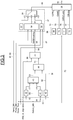
- the figure 3 illustrates the main elements included in the control means 3 of the torque transfer actuator among which there is a means 36 for determining the activity of the anti-lock system of the wheels, a control means 37 of the driving mode, means 38 for determining the torque setpoints, and a switching means 39 controlled.
- Other means that are not shown make it possible to determine the signal relating to the traction mode required by the driver Driver_req, the signal relating to the active torque transfer mode ETC_mode, and the signal relating to the state of the torque transfer actuator. ETC_state.
- the means 39 for determining the activity of the anti-lock system of the wheels comprises a means 40 for comparing the speed of the vehicle with a threshold speed, a first comparison means 41 of the driver's mode of driving request and a second comparison means 42 of the driver mode request, an AND type 43, an OR type 44 and an AND type 45.
- the means 40 for comparing the speed of the vehicle with a threshold speed is connected at input to the determination means 1 via the connection 46 and at the output to the logic operator 43 of the AND type via the connection 47.
- the first comparison means 41 of the driver mode request is connected at the input to the manual control device 4 via the connection 48 and at the output to the logic operator 43 of the AND type via the connection 49.
- the AND type logic operator 43 is connected at input to the determination means 1 by a connection 50 carrying a request signal of a braking Switch_brk, and at the output to the logical operator 44 of the OR type via the connection 53.
- the second comparison means 42 of the driver mode request is connected at the input to the manual control member 4 by the connection 51 carrying the signal relating to the traction mode required by the driver Driver Driver, and output to the driver. OR logic operator 44 by connection 52.
- the OR logic operator 44 is connected at the output by the connection 54 to the AND type logic operator 45.
- the AND type logic operator 45 is also input to the anti-lock wheel control means 2 via the connection 55.
- the ET type logic operator 45 receives the anti-lock control of the ABS_in_regulation wheels via the connection 55.
- the output of the AND-type logic operator 45 coincides with the output of the determination means 36 of the anti-lock system activity of the wheels and is connected to the control means 37 of the driving mode via the connection 56.
- the means 36 for determining the activity of the anti-lock system of the wheels receives via the connection 46 a value v of the speed of the vehicle. This value is compared by the comparison means 40 of the speed with a stored value Vthreshold. A logic value "true” is output if the value of the speed v is greater than or equal to the value Vthreshold, otherwise the logical value "false" is issued.
- the means 36 for determining the activity of the anti-lock system of the wheels receives via the connection 50 a logic value coming from the determination means 1 and carrying the value "true” if the brake pedal is depressed.
- the value Driver_req is received by the connection 48 of the control means 3 of the torque transfer actuator.
- the first comparison means 41 of the driver's driving mode request compares the value Driver_req to the stored value 4WDLock. If the comparison is verified, a logic value "true” is emitted at the output of the first comparison means 41, otherwise the logical value "false” is emitted.
- the second comparison means 42 of the driver's driving mode request compares the value Driver_req to the stored value 4WDLock. If the comparison is verified, a "false” logic value is emitted at the output of the second comparison means 42, otherwise a "true” logic value is emitted.
- the request signal of a Switch_brk braking carried by the connection 50 from the determination means is of logic type.
- the Switch_brk signal takes the logical value "false” when no braking is required, or if the brake detection sensor is unreliable.
- the signal Switch_brk takes the logical value "true” if a braking is detected, whatever the amplitude of the braking required.
- the AND type logic operator 43 receives as input the logic signals emitted by the comparison means 40 of the speed and by the first comparison means 41 of the driver mode request and the signal carried by the connection 50. If all these signals carry a logical value "true”, the AND logic operator 43 outputs a logic value "true”, otherwise a logical value "false” is issued.
- the OR logic operator 44 receives as input the logic signals emitted by the AND-type logic operator 43 and by the second comparison means 42 of the driver mode request. If at least one of these signals carries a logical value "true”, the OR logic operator 44 outputs a logic value "true”, otherwise a logic value "false” is issued.
- the means 36 for determining the activity of the anti-lock system of the wheels receives via the connection 55 the command anti-lock ABS_in_regulation wheels from the control means 2 anti-lock wheels.
- the AND-type logic operator 45 receives as input the logic signal emitted by the OR logic operator 44 and the anti-lock control of the ABS_in_regulation wheels. If all these signals carry a logic value "true”, the AND-type logic operator 45 outputs an ABSBraking wheel anti-lock system trip control signal carrying a logic value "true”, otherwise a logic value " false "is issued.
- the driver determines whether the driver requires an all-wheel-drive mode (4WDLock) or not. If all-wheel-drive (4WDLock) mode is required, and if the vehicle speed is greater than or equal to a threshold speed, and if the anti-lock braking system is active, the anti-lock braking system (ABS) is triggered. Likewise, if a mode other than four-wheel drive is required, and anti-lock braking is active, the anti-lock braking system (ABS) is triggered. In other cases, the anti-lock braking system (ABS) is not triggered. This is particularly the case if the anti-lock wheels are inactive.
- all-wheel-drive (4WDLock) mode is required, and if the vehicle speed is greater than or equal to a threshold speed, and if the anti-lock braking system is active, the anti-lock braking system (ABS) is triggered. Likewise, if a mode other than four-wheel drive is required, and anti-lock braking is active, the anti-lock braking system
- ABS anti-lock wheel system
- the control means 37 of the driving mode comprises a memory 57, an OR logic operator 58, a determination means 59 of the driving mode to be activated, and a controlled switch 60.
- the controlled switch 60 is connected at the input by a connection 61 to the memory 57, and by the connection 63 to the determining means 59 of the driving mode to be activated.
- the controlled switch 60 is furthermore input-connected via its control terminal to the OR logic operator 58 via the connection 62.
- the OR logic operator 58 is input connected to the determination means 36 of the anti-lock system activity of the wheels via the connection 56, carrying the trip control signal of the ABSBraking anti-lock system, and to the determination means 1 by the connection 65 and the connection 66.
- the determining means 59 of the driving mode to be activated is connected in input to the determination means 1 by the connection 67, bypass of the connection 46, and the connection 68, bypass of the connection 48.
- the controlled switch 60 is connected at the output to the switching means 39 controlled by the connection 64.
- the OR logic operator 58 receives means 1 for determining a logic signal for activating the Hand_Brk handbrake via the connection 65, and a logic signal for activating the depression of the Pedal_Brk brake pedal via the connection 66.
- the OR logic operator 58 outputs a logic value "true” if at least one of the input signals carries the logic value "true”, otherwise a "false” value is transmitted.
- the memory 57 sends to the controlled switch 60 a control signal of the switching means 39 able to cause switching of said switching means 39 so that the braking torque setpoint is outputted from the switching means 39.
- the determining means 59 of the driving mode to be activated receives as input a signal carrying the request of the driver Driver_req by the connection 68, and the speed v of the vehicle via the connection 67, and may receive other data, such as for example the outside temperature.
- the determining means 59 of the driving mode to be activated transmits a control signal to the controlled switch 60 for controlling the switching means 39.
- This control signal transmitted by the determining means 59 is able to cause the switching. of said switching means 39 so that the torque setpoint corresponding to the driving mode determined by the determining means 59 of the driving mode to be activated is applied.
- the controlled switch 60 transmits the signal received from the memory 57 to the switching means 39 if the logic signal received at its control terminal from the OR logic operator 58 has the logic value "true”. If the logic signal received on the control terminal from the OR logic operator 58 has the logic value "false", the signal received from the determining means 59 of the driving mode to be activated is transmitted to the control means. switching 39.
- the mode control signal outputted from the controlled switch 60 depends on the logic signal received from the OR type logic operator 58.
- the means 38 for determining the torque setpoints comprises means 69 for determining the torque setpoint in two-wheel drive mode (2WD), means for determining the torque setpoint in four-wheel-drive (4WD) mode, means for determining the torque set point. determining the torque setpoint 4WDLock in four-wheel drive mode, and determining means 72 for determining the torque setpoint in braking mode.
- the means 38 for determining the torque setpoints is connected at input to the determination means 1 by the connection 73.
- the controlled switching means 39 is connected in input to the determining means 69 of the torque setpoint in two-wheel drive (2WD) mode via the connection 74, by means of determination 70 of the torque setpoint in four-wheel drive mode (4WD). ) by the connection 75, by means of determination 71 of the off-road four-wheel drive torque setpoint (4WDLock) via the connection 76, and by means of determination 72 of the braking torque setpoint via the connection 77.
- the controlled switching means 39 is also connected as input to the control means 37 of the driving mode via its control terminal.
- the controlled switching means 39 is connected at the output by the connection 15 to the torque transfer actuator 5.
- the determination means 38 of the torque setpoints receives on its inputs values from the determining means and characterizing the behavior of the vehicle. Based on these values, the determination means 69 for determining the torque setpoint in two-wheel drive mode (2WD) determines the torque setpoint in two-wheel drive mode C2WD, the determination means 70 for the four-wheel torque setpoint.
- motor (4WD) determines a torque setpoint in four-wheel drive mode C4WD
- the determination means 71 of the off-road four-wheel drive torque setpoint (4WDLock) determines the torque setpoint in all terrain four-wheel drive mode C4WDLock
- the means 72 for determining the torque setpoint in the braking mode determines the torque setpoint in the CBrake braking mode.
- the determination of the different instructions is known to those skilled in the art. It should be noted that the torque setpoint in CBrake braking mode can be a constant value, a value dependent on the speed of the vehicle or other parameters.
- the controlled switching means 39 emits torque transfer control to the torque transfer actuator 5.
- the torque transfer control is equal to the torque setpoint corresponding to the signal received from the control means 37 of the driving mode.
- the switching means 39 determines the torque setpoint to be applied as a function of the signal command issued by the determining means 59 of the driving mode to be activated.
- control means 3 of the torque transfer actuator is capable of transmitting a logic deactivation signal to the antilocking wheel control means 2. This signal is emitted when a bridge crossing situation is detected as a function of the speed of each wheel, the engine torque and the torque transferred to the rear axle.
- the detection conditions of a bridge crossing situation are a sum of the rotational speeds of two wheels according to a diagonal (for example left front wheel and right rear wheel) lower than a first threshold value, a sum of rotation speeds. the other two wheels greater than a second threshold value, and a torque transferred to the rear axle greater than a third threshold value.
- the deactivation signal is emitted. The transmission of the signal is stopped as soon as one of these conditions is no longer verified.
- a bridge crossing situation usually occurs when crossing obstacles in off-road mode.
- the deactivation of the anti-lock braking system during braking makes it possible to avoid an oscillation of the logic conditions processed by the control means 3 of the torque transfer actuator, in particular by the anti-lock control of the ABS_in_regulation wheels coming from the means
- An oscillation of the value carried by the anti-lock control of the ABS_in_regulation wheels can then lead to an oscillation in the control signal received by the controlled switch 60 which can then generate an oscillation in the torque transfer control transmitted by the switching means 39 controlled to the torque transfer actuator 5.
- Such oscillation of the torque transfer control can be at best inconvenient for the driver, at worst dangerous for the safety of the vehicle.
- the control system allows the anti-lock braking and torque transfer to cooperate, which makes it possible to develop a torque transfer setpoint which is not erroneously determined taking into account an unjustified release of the anti-lock. wheels.
Landscapes
- Engineering & Computer Science (AREA)
- Transportation (AREA)
- Mechanical Engineering (AREA)
- Chemical & Material Sciences (AREA)
- Combustion & Propulsion (AREA)
- Automation & Control Theory (AREA)
- Regulating Braking Force (AREA)
- Arrangement And Driving Of Transmission Devices (AREA)
Claims (11)
- System zur Steuerung einer Drehmomentkupplung (5) für ein Kraftfahrzeug mit vier Antriebsrädern, umfassend Bestimmungsmittel (1) und ein Antiblockiersystem der Räder, wobei das System umfasst:ein Antiblockiersteuerungsmittel (2) der Räder und ein Steuermittel (3) der Drehmomentkupplung, die geeignet sind zusammenzuwirken, um die Steuerung einer Drehmomentübertragung in Richtung der Drehmomentkupplung (5) zu entsenden, wobei das Antiblockiersteuerungsmittel (2) der Räder geeignet ist, eine Antiblockiersteuerung der Räder in Abhängigkeit von der Steuerung einer Drehmomentübertragung, die von dem Steuerungsmittel (3) der Drehmomentkupplung empfangen wird, zu bestimmen,wobei das Steuerungselement (3) der Drehmomentkupplung geeignet ist, eine Steuerung einer Drehmomentübertragung in Abhängigkeit von der Antiblockiersteuerung der Räder zu bestimmen, dadurch gekennzeichnet, dass das System ein Mittel (18) zur Bestimmung der Fahrsituation umfasst, das geeignet ist, ein Steuerungssignal in Richtung eines gesteuerten Umschalters (19) in Abhängigkeit von den Signalen, die von den Bestimmungsmitteln (1) empfangen werden, und von der Steuerung einer Drehmomentübertragung, die von dem Steuerungsmittel (3) der Drehmomentkupplung empfangen wird, zu entsenden, wobei der gesteuerte Umschalter (19) geeignet ist, ein Erkennungssignal eines Blockierens der Räder zu entsenden, sowie ein Mittel (20) zur Beurteilung des Bremsniveaus umfasst, das geeignet ist, ein Signal in Abhängigkeit von dem Drucksignal in dem Bremskreis, das von den Bestimmungsmitteln (1) empfangen wird, zu entsenden,wobei ein logischer Operator (21) des Typs ET geeignet ist, eine Antiblockiersteuerung der Räder in Zusammenhang mit dem Funktionszustand des Antiblockiersteuerungsmittels der Räder in Abhängigkeit von den Signalen, die von dem gesteuerten Umschalter (19) und dem Mittel (20) zur Beurteilung des Bremsniveaus empfangen werden, zu entsenden.
- Steuerungssystem nach Anspruch 1, umfassend ein manuelles Steuerungselement (4), das mit dem Steuerungsmittel (3) der Drehmomentkupplung verbunden ist, und
wobei das manuelle Steuerungselement (4) mehrere Positionen einnehmen kann und von dem Fahrer des Fahrzeugs betätigt wird und geeignet ist, ein Signal je nach der vom Fahrer ausgewählten Position zu entsenden. - Steuerungssystem nach Anspruch 1, umfassend ein erstes Erkennungsmittel (16) des Blockierens der Räder und ein zweites Erkennungsmittel (17) des Blockierens der Räder, die jeweils an eine Klemme des gesteuerten Umschalters (19) angeschlossen und jeweils geeignet sind, das Bestehen eines Blockierens der Räder beim Bremsen in Abhängigkeit von den Drehgeschwindigkeitssignalen jedes Rades, die von den Bestimmungsmitteln (1) empfangen werden, zu bestimmen.
- Steuerungssystem nach Anspruch 1, umfassend ein Mittel (36) zur Bestimmung der Aktivität des Antiblockiersystems der Räder, das geeignet ist, ein Signal zur Steuerung des Auslösens des Antiblockiersystems der Räder in Abhängigkeit von den Signalen, die von den Bestimmungsmitteln empfangen werden, und der Antiblockiersteuerung der Räder, die von dem Antiblockiersteuerungsmittel (2) der Räder empfangen wird, zu bestimmen.
- Steuerungssystem nach Anspruch 4, umfassend ein Steuerungsmittel (37) des Fahrmodus, das geeignet ist, den Fahrmodus, der an die Drehmomentkupplung (5) anzulegen ist, in Abhängigkeit von dem Aktivierungssignal der Handbremse (65), dem Aktivierungssignal des Tretens des Bremspedals (66), der Geschwindigkeit des Fahrzeugs (67), der Forderung des Fahrers (68), Signalen, die von den Bestimmungsmitteln (1) empfangen werden, und von dem Signal zur Steuerung des Auslösens des Antiblockiersystems der Räder, das von dem Mittel (36) zur Bestimmung der Aktivität des Antiblockiersystems der Räder empfangen wird, zu bestimmen, wobei das Steuerungsmittel (37) des Fahrmodus geeignet ist, ein Signal zur Modussteuerung zu entsenden.
- Steuerungssystem nach Anspruch 5, umfassend ein Mittel (38) zur Bestimmung der Drehmomentsollwerte und ein Umschaltmittel (39), wobei das Mittel zur Bestimmung (38) der Drehmomentsollwerte geeignet ist, die Drehmomentsollwerte zu bestimmen, die an die Drehmomentkupplung (5) für jeden Fahrmodus, der vom Fahrer gewählt werden kann, sowie für einen Bremsmodus anzulegen sind, wobei das Umschaltmittel (39) geeignet ist, eine Steuerung einer Drehmomentübertragung in Richtung der Drehmomentkupplung (5) in Abhängigkeit von dem Modussteuerungssignal, das von dem Steuerungsmittel (37) des Fahrmodus empfangen wird, und von den Signalen, die von dem Mittel (38) zur Bestimmung der Drehmomentsollwerte empfangen werden, zu entsenden.
- Verfahren zur Steuerung einer Drehmomentübertragung für ein Kraftfahrzeug mit vier Antriebsrädern mit einer Antiblockiersteuerung der Räder und einer Drehmomentübertragungssteuerung, wobei die Antiblockiersteuerung der Räder von der Drehmomentübertragungssteuerung abhängt, und
die Drehmomentübertragungssteuerung von der Antiblockiersteuerung der Räder abhängt, wobei ein Erkennungssignal eines Blockierens der Räder in Abhängigkeit von mindestens zwei Erkennungsmodi eines Blockierens der Räder und in Abhängigkeit von der Geschwindigkeit des Fahrzeugs und von der Drehmomentübertragungssteuerung, insbesondere der Forderung des Fahrers nach einem Fahrmodus, dem Zustand der Drehmomentkupplung und dem aktiven Fahrmodus in der Drehmomentkupplung bestimmt wird, wobei das Verfahren dadurch gekennzeichnet ist, dass:- ein Erkennungssignal eines Bremsens bestimmt wird, wenn der Druck des Bremssystems höher als ein Schwellenwert ist,- die Antiblockiersteuerung der Räder in Abhängigkeit von dem Erkennungssignal eines Blockierens der Räder und von dem Erkennungssignal eines Bremsens bestimmt wird, und- ein Signal zur Steuerung einer Auslösung des Antiblockiersystems der Räder in Abhängigkeit von der Geschwindigkeit des Fahrzeugs, der Antiblockiersteuerung der Räder, der Forderung des Fahrers nach einem Fahrmodus, und einem Bremsforderungssignal bestimmt wird. - Steuerungsverfahren nach Anspruch 7, bei dem die Antiblockiersteuerung der Räder von der Drehmomentübertragungssteuerung, insbesondere von der Forderung des Fahrers nach einem Fahrmodus, von dem Zustand der Drehmomentkupplung und dem aktiven Fahrmodus in der Drehmomentkupplung abhängt.
- Steuerungsverfahren nach Anspruch 7, bei dem ein erster Erkennungsmodus des Blockierens der Räder ausgewählt wird, wenn die Forderung des Fahrers nach einem Fahrmodus nicht Geländemodus ist, oder wenn der aktive Fahrmodus in der Drehmomentkupplung nicht Geländemodus ist, oder wenn die Geschwindigkeit des Fahrzeugs höher als ein Schwellenwert ist, oder wenn ein anderer Ausfall der Drehmomentkupplung (5) als ein thermischer Ausfall erkannt wird.
- Steuerungsverfahren nach Anspruch 7, bei dem ein zweiter Erkennungsmodus des Blockierens der Räder ausgewählt wird, wenn der erste Erkennungsmodus des Blockierens der Räder nicht aktiviert wurde, wobei der zweite Erkennungsmodus des Blockierens der Räder eine weniger große Erkennungsempfindlichkeit als die Erkennungsempfindlichkeit des ersten Erkennungsmodus des Blockierens der Räder aufweist.
- Steuerungsverfahren nach Anspruch 7, bei dem ein Drehmomentübertragungssollwert im Zweiradantriebsmodus, ein Drehmomentübertragungssollwert im Vierradantrieb, ein Drehmomentübertragungssollwert im Gelände-Vierradantrieb und ein Drehmomentübertragungssollwert im Bremsmodus bestimmt wird,
ein Drehmomentübertragungssollwert in Abhängigkeit von der Geschwindigkeit des Fahrzeugs, der Forderung des Fahrers nach einem Fahrmodus, dem Treten des Bremspedals, der Aktivierung der Handbremse und einem Steuerungssignal eines Auslösens des Antiblockiersystems der Räder ausgewählt wird, und
die Drehmomentübertragungssteuerung in Abhängigkeit von dem ausgewählten Drehmomentübertragungssollwert entsandt wird.
Applications Claiming Priority (2)
| Application Number | Priority Date | Filing Date | Title |
|---|---|---|---|
| FR1052768A FR2958586B1 (fr) | 2010-04-12 | 2010-04-12 | Systeme de commande d'un actionneur de transfert de couple a modes de fonctionnement multiples. |
| PCT/FR2011/050827 WO2011128570A1 (fr) | 2010-04-12 | 2011-04-11 | Système de commande d'un actionneur de transfert de couple à modes de fonctionnement multiples |
Publications (2)
| Publication Number | Publication Date |
|---|---|
| EP2558320A1 EP2558320A1 (de) | 2013-02-20 |
| EP2558320B1 true EP2558320B1 (de) | 2018-05-30 |
Family
ID=42289656
Family Applications (1)
| Application Number | Title | Priority Date | Filing Date |
|---|---|---|---|
| EP11731006.0A Not-in-force EP2558320B1 (de) | 2010-04-12 | 2011-04-11 | System und verfahren zum steuern einer drehmomentkupplung entsprechend mehrerer betriebsarten |
Country Status (5)
| Country | Link |
|---|---|
| US (1) | US20130073159A1 (de) |
| EP (1) | EP2558320B1 (de) |
| CN (1) | CN102971172B (de) |
| FR (1) | FR2958586B1 (de) |
| WO (1) | WO2011128570A1 (de) |
Families Citing this family (5)
| Publication number | Priority date | Publication date | Assignee | Title |
|---|---|---|---|---|
| GB2514161B (en) * | 2013-05-16 | 2015-09-02 | Jaguar Land Rover Ltd | Vehicle control system and method |
| US9108518B2 (en) * | 2013-06-11 | 2015-08-18 | Electro-Motive Diesel, Inc. | Axle torque control corresponding to wheel sizes |
| FR3006949B1 (fr) * | 2013-06-17 | 2016-10-21 | Renault Sa | Systeme et procede de surveillance du couple fourni par le moteur d'un vehicule automobile electrique ou hybride. |
| FR3012098B1 (fr) * | 2013-10-17 | 2017-01-13 | Renault Sa | Systeme et procede de controle de vehicule avec gestion de defauts |
| KR101551124B1 (ko) * | 2014-10-10 | 2015-09-07 | 현대자동차주식회사 | Abs 협조 제어 성능을 강화한 전자제어 4wd시스템 및 제어방법 |
Family Cites Families (55)
| Publication number | Priority date | Publication date | Assignee | Title |
|---|---|---|---|---|
| US4770266A (en) * | 1985-08-13 | 1988-09-13 | Mazda Motor Corporation | Brake control system for four-wheel drive vehicle |
| JPH01114523A (ja) * | 1987-10-27 | 1989-05-08 | Fuji Heavy Ind Ltd | 4輪駆動車の駆動力制御装置 |
| US5247443A (en) | 1987-12-23 | 1993-09-21 | Dana Corporation | Electronic control for vehicle four wheel drive system |
| DE3843520C1 (de) * | 1988-12-23 | 1990-04-19 | Daimler-Benz Aktiengesellschaft, 7000 Stuttgart, De | |
| US5105901A (en) * | 1989-12-09 | 1992-04-21 | Mazda Motor Corporation | Four wheel drive system |
| JP2707806B2 (ja) * | 1990-06-15 | 1998-02-04 | 三菱自動車工業株式会社 | 4輪駆動用アンチスキッドブレーキ制御方法 |
| JP2998327B2 (ja) * | 1991-08-10 | 2000-01-11 | アイシン精機株式会社 | アンチスキッド制御装置 |
| US6000488A (en) * | 1992-06-24 | 1999-12-14 | Borg-Warner Automotive, Inc. | Motor vehicle transfer case |
| US5472265A (en) * | 1992-12-10 | 1995-12-05 | Toyota Jidosha Kabushiki Kaisha | Antilock braking control apparatus for electric vehicle |
| JP3301183B2 (ja) | 1993-11-24 | 2002-07-15 | 日産自動車株式会社 | 車両の前後輪間駆動力配分制御装置 |
| JPH07205675A (ja) * | 1994-01-26 | 1995-08-08 | Honda Motor Co Ltd | アンチロックブレーキ制御装置付車両における駆動状態切換制御方法 |
| JP3098958B2 (ja) * | 1996-05-17 | 2000-10-16 | 三菱電機株式会社 | アンチロックブレーキ制御装置 |
| JP3829374B2 (ja) | 1996-10-16 | 2006-10-04 | 日産自動車株式会社 | 車両の駆動力制御装置 |
| JPH1191537A (ja) * | 1997-09-19 | 1999-04-06 | Unisia Jecs Corp | ブレーキ制御装置 |
| US6496769B1 (en) * | 1998-05-04 | 2002-12-17 | O'dea Kevin Austin | Four wheel drive anti-lock brake control having torque transfer alleviation |
| JP2001071775A (ja) * | 1999-09-08 | 2001-03-21 | Toyoda Mach Works Ltd | 4輪駆動車の駆動力分配制御装置 |
| DE60031647T2 (de) * | 2000-03-20 | 2007-02-15 | Robert Bosch Gmbh | Bremssteuerung für Allradfahrzeuge mit Viskosekupplung |
| US20010053953A1 (en) * | 2000-06-16 | 2001-12-20 | Shao-Wei Gong | Antilock braking control method and system |
| JP2002087095A (ja) * | 2000-09-12 | 2002-03-26 | Komatsu Ltd | 車両のタイヤロック防止装置 |
| JP3525879B2 (ja) | 2000-09-19 | 2004-05-10 | 日産自動車株式会社 | 4輪駆動車の前後輪トルク配分制御装置 |
| DE10128357A1 (de) * | 2001-06-13 | 2003-03-06 | Continental Teves Ag & Co Ohg | Verfahren zur Regelung der Fahrstabilität |
| JP3589202B2 (ja) | 2001-07-13 | 2004-11-17 | 日産自動車株式会社 | 4輪駆動車両の駆動力制御装置 |
| WO2003072410A2 (de) * | 2002-02-28 | 2003-09-04 | Daimlerchrysler Ag | Vorrichtung und verfahren zur beeinflussung der arbeitsweise wenigstens einer in einem fahrzeug angeordneten fahrzeugstabilisierungsvorrichtung |
| US6688415B2 (en) * | 2002-03-14 | 2004-02-10 | Ford Global Technologies, Llc | Stability control throttle compensation on vehicles with passive all wheel drive systems |
| US6704635B2 (en) * | 2002-06-26 | 2004-03-09 | General Motors Corporation | Method for determining optimal ABS slip and deceleration thresholds |
| US6810318B2 (en) * | 2002-09-13 | 2004-10-26 | General Motors Corporation | Drive torque transfer scheme |
| JP2004106649A (ja) * | 2002-09-17 | 2004-04-08 | Fuji Heavy Ind Ltd | 4輪駆動車の動力配分制御装置 |
| JP4192631B2 (ja) * | 2003-02-28 | 2008-12-10 | 株式会社ジェイテクト | 4輪駆動車のトルク配分制御装置 |
| US6862511B1 (en) * | 2003-09-11 | 2005-03-01 | Ford Global Technologies, Llc | Vehicle torque coordination |
| JP2005125986A (ja) * | 2003-10-27 | 2005-05-19 | Fuji Heavy Ind Ltd | 車両制御装置および車両制御方法 |
| US20050116537A1 (en) * | 2003-12-01 | 2005-06-02 | Zalewski John D. | Combination braking and traction control system for a motor vehicle |
| US7822524B2 (en) * | 2003-12-26 | 2010-10-26 | Toyota Jidosha Kabushiki Kaisha | Vehicular drive system |
| US7197383B2 (en) * | 2004-02-17 | 2007-03-27 | Ford Global Technologies, Llc | System for limiting reactive torque in powertrains |
| WO2006000560A1 (de) * | 2004-06-24 | 2006-01-05 | Continental Teves Ag & Co. Ohg | Verfahren zur steuerung eines bremssystems eines allradgetriebenen kraftfahrzeuges |
| DE602005003617T2 (de) | 2004-08-19 | 2008-04-10 | Honda Motor Co., Ltd. | Verfahren zur Kontrolle eines Allradfahrzeugs |
| SE0402539D0 (sv) * | 2004-10-21 | 2004-10-21 | Haldex Traction Ab | All wheel drive system |
| JP4806413B2 (ja) * | 2005-08-29 | 2011-11-02 | 株式会社小松製作所 | アンチロックブレーキシステム制御装置及び制御方法 |
| US7337053B2 (en) * | 2006-02-15 | 2008-02-26 | Eaton Corporation | Stability-enhanced traction control with electrically controlled center coupler |
| DE102006027834B4 (de) * | 2006-06-16 | 2014-02-13 | Engineering Center Steyr Gmbh & Co. Kg | Verfahren zur Bestimmung eines Drehmoments |
| JP4969936B2 (ja) * | 2006-07-28 | 2012-07-04 | 富士重工業株式会社 | 車両の駆動力配分制御装置 |
| JP2010516556A (ja) * | 2007-01-25 | 2010-05-20 | 本田技研工業株式会社 | 車両の安定性を改善するための車両システムの制御方法 |
| CN101011931A (zh) * | 2007-01-30 | 2007-08-08 | 重庆大学 | 一种isg型全轮驱动混合动力汽车的驱动系统及驱动方法 |
| US7832518B2 (en) * | 2007-03-22 | 2010-11-16 | Ford Global Technologies, Llc | Torque distribution control in a motor vehicle |
| FR2918334B1 (fr) * | 2007-07-06 | 2009-09-11 | Renault Sas | Procede de traitement de donnees dans un dispositif d'assistance aux manoeuvres en cote d'un vehicule automobile |
| FR2918945B1 (fr) * | 2007-07-19 | 2009-10-09 | Messier Bugatti Sa | Procede de commande d'un frein de vehicule avec correction en couple |
| US8055425B2 (en) * | 2008-03-14 | 2011-11-08 | Ford Global Technologies, Llc | Increased capability modular vehicle-dynamics control architecture |
| JP5381203B2 (ja) * | 2008-03-31 | 2014-01-08 | 株式会社アドヴィックス | 車両の運動制御装置 |
| SE533094C2 (sv) * | 2008-04-24 | 2010-06-29 | Haldex Traction Ab | Torque vectoring-anordning och medel för dess kontroll |
| FR2931426B1 (fr) * | 2008-05-20 | 2010-10-22 | Renault Sas | Systeme et procede de commande d'un vehicule a quatre roues motrices |
| FR2935656B1 (fr) * | 2008-09-05 | 2015-03-20 | Renault Sas | Systeme et procede de gestion du freinage d'un vehicule automobile |
| DE102009053817C5 (de) * | 2009-11-18 | 2016-07-07 | Knorr-Bremse Systeme für Nutzfahrzeuge GmbH | Fahrzeug mit einer Bremsmoment von Hinterrädern auf die Vorderräder übertragenden Bremseinrichtung mit Bremsschlupfregelung |
| JP4913205B2 (ja) * | 2009-12-18 | 2012-04-11 | 日立オートモティブシステムズ株式会社 | 電動車両の制動制御装置 |
| FR2958583B1 (fr) * | 2010-04-09 | 2012-04-20 | Renault Sas | Systeme et procede de limitation de couple moteur d'un vehicule a quatre roues motrices |
| FR2958607B1 (fr) * | 2010-04-12 | 2012-03-23 | Renault Sa | Procede de commande de repartition de couple pour un vehicule motorise a quatre roues motrices et vehicule correspondant |
| US8428840B2 (en) * | 2010-10-29 | 2013-04-23 | GM Global Technology Operations LLC | Method for controlling torque at one or more wheels of a vehicle |
-
2010
- 2010-04-12 FR FR1052768A patent/FR2958586B1/fr not_active Expired - Fee Related
-
2011
- 2011-04-11 US US13/640,415 patent/US20130073159A1/en not_active Abandoned
- 2011-04-11 EP EP11731006.0A patent/EP2558320B1/de not_active Not-in-force
- 2011-04-11 WO PCT/FR2011/050827 patent/WO2011128570A1/fr not_active Ceased
- 2011-04-11 CN CN201180028458.2A patent/CN102971172B/zh not_active Expired - Fee Related
Non-Patent Citations (1)
| Title |
|---|
| None * |
Also Published As
| Publication number | Publication date |
|---|---|
| EP2558320A1 (de) | 2013-02-20 |
| CN102971172B (zh) | 2016-06-22 |
| RU2012147844A (ru) | 2014-05-20 |
| WO2011128570A1 (fr) | 2011-10-20 |
| FR2958586A1 (fr) | 2011-10-14 |
| CN102971172A (zh) | 2013-03-13 |
| FR2958586B1 (fr) | 2014-05-09 |
| US20130073159A1 (en) | 2013-03-21 |
Similar Documents
| Publication | Publication Date | Title |
|---|---|---|
| EP2558325B1 (de) | Drehmomentverteilungssteuerverfahren für ein motorfahrzeug mit vierradantrieb und entsprechendes fahrzeug | |
| EP2555939B1 (de) | System und verfahren zur begrenzung des motordrehmoments eines fahrzeugs mit allradantrieb | |
| FR2750367A1 (fr) | Dispositif et procede pour la commande automatique d'un blocage de differentiel sur un vehicule automobile | |
| EP2558320B1 (de) | System und verfahren zum steuern einer drehmomentkupplung entsprechend mehrerer betriebsarten | |
| FR2923436A1 (fr) | Systeme de controle du comportement d'un vehicule comportant une determination de sa vitesse par rapport au sol | |
| FR2765682A1 (fr) | Procede et dispositif pour determiner la masse d'un vehicule | |
| EP2555940B1 (de) | Steuerverfahren der funktion einer mechanischen kupplungseinrichtung der ersten und zweiten achsen eines kraftfahrzeugs | |
| FR2770466A1 (fr) | Vehicule automobile equipe d'un dispositif de manoeuvre automatisee d'un embrayage | |
| FR3092811A1 (fr) | Procede et systeme de pilotage d’un essieu electrique d’une remorque ou semi-remorque | |
| EP1368204B1 (de) | Verfahren zur automatischen ortung der vor- und hinterräder eines kraftfahrzeuges | |
| FR2589115A1 (fr) | Systeme de freinage a regulation du glissement pour un vehicule dont toutes les roues sont motrices | |
| EP1621431B1 (de) | Verfahren und Vorrichtung zur Bremskraftverteilung vorne/hinten für ein Kraftfahrzeug | |
| EP2307253A1 (de) | Vorrichtung zur bestimmung der querbeschleunigung eines motorfahrzeugs und entsprechendes verfahren | |
| EP2033867B1 (de) | Automatisches System zum Halten eines Fahrzeugs am Hang | |
| FR2904958A1 (fr) | Dispositif d'anti-patinage ameliore des roues motrices d'un vehicule et procede pour sa mise en oeuvre. | |
| EP1621432B1 (de) | Vorrichtung und Verfahren zur Bremssteuerung der Innen- bzw. Aussenräder bei einer Kurvenbremsung | |
| FR2915802A1 (fr) | Procede et systeme de determination d'adherence pour vehicule automobile | |
| FR2869004A1 (fr) | Unite de commande de systeme de vehicule dotee de capacites de commandes auxiliaires | |
| EP2558324B1 (de) | Verfahren zur steuerung eines mittels zur mechanischen kopplung der achse eines getriebesystems eines motorfahrzeugs | |
| WO2015082256A1 (fr) | Systeme et procede de detection indirecte du sous-gonflage d'un pneumatique | |
| WO2009095627A1 (fr) | Dispositif et procede de commande de la repartition du couple moteur d'un vehicule a quatre roues motrices | |
| FR2932878A1 (fr) | Dispositif et procede de l'estimation de la pente du terrain pour le roulage d'un vehicule automobile. | |
| WO2011138548A2 (fr) | Systeme de transmission a differentiel de type a arbre neutre comportant un dispositif de freinage regeneratif | |
| JP2004511380A (ja) | トルクバイアスシステム | |
| FR2892081A1 (fr) | Dispositif permettant de maintenir un vehicule automobile en place dans une pente, procede d'exploitation d'un tel dispositif et vehicule automobile equipe d'un tel dispositif |
Legal Events
| Date | Code | Title | Description |
|---|---|---|---|
| PUAI | Public reference made under article 153(3) epc to a published international application that has entered the european phase |
Free format text: ORIGINAL CODE: 0009012 |
|
| 17P | Request for examination filed |
Effective date: 20120927 |
|
| AK | Designated contracting states |
Kind code of ref document: A1 Designated state(s): AL AT BE BG CH CY CZ DE DK EE ES FI FR GB GR HR HU IE IS IT LI LT LU LV MC MK MT NL NO PL PT RO RS SE SI SK SM TR |
|
| DAX | Request for extension of the european patent (deleted) | ||
| 17Q | First examination report despatched |
Effective date: 20160622 |
|
| STAA | Information on the status of an ep patent application or granted ep patent |
Free format text: STATUS: EXAMINATION IS IN PROGRESS |
|
| GRAP | Despatch of communication of intention to grant a patent |
Free format text: ORIGINAL CODE: EPIDOSNIGR1 |
|
| STAA | Information on the status of an ep patent application or granted ep patent |
Free format text: STATUS: GRANT OF PATENT IS INTENDED |
|
| GRAJ | Information related to disapproval of communication of intention to grant by the applicant or resumption of examination proceedings by the epo deleted |
Free format text: ORIGINAL CODE: EPIDOSDIGR1 |
|
| GRAP | Despatch of communication of intention to grant a patent |
Free format text: ORIGINAL CODE: EPIDOSNIGR1 |
|
| INTG | Intention to grant announced |
Effective date: 20171020 |
|
| INTG | Intention to grant announced |
Effective date: 20171102 |
|
| GRAS | Grant fee paid |
Free format text: ORIGINAL CODE: EPIDOSNIGR3 |
|
| GRAA | (expected) grant |
Free format text: ORIGINAL CODE: 0009210 |
|
| STAA | Information on the status of an ep patent application or granted ep patent |
Free format text: STATUS: THE PATENT HAS BEEN GRANTED |
|
| AK | Designated contracting states |
Kind code of ref document: B1 Designated state(s): AL AT BE BG CH CY CZ DE DK EE ES FI FR GB GR HR HU IE IS IT LI LT LU LV MC MK MT NL NO PL PT RO RS SE SI SK SM TR |
|
| REG | Reference to a national code |
Ref country code: GB Ref legal event code: FG4D Free format text: NOT ENGLISH |
|
| REG | Reference to a national code |
Ref country code: CH Ref legal event code: EP |
|
| REG | Reference to a national code |
Ref country code: AT Ref legal event code: REF Ref document number: 1003255 Country of ref document: AT Kind code of ref document: T Effective date: 20180615 |
|
| REG | Reference to a national code |
Ref country code: IE Ref legal event code: FG4D Free format text: LANGUAGE OF EP DOCUMENT: FRENCH |
|
| REG | Reference to a national code |
Ref country code: DE Ref legal event code: R096 Ref document number: 602011048783 Country of ref document: DE |
|
| REG | Reference to a national code |
Ref country code: NL Ref legal event code: MP Effective date: 20180530 |
|
| REG | Reference to a national code |
Ref country code: LT Ref legal event code: MG4D |
|
| PG25 | Lapsed in a contracting state [announced via postgrant information from national office to epo] |
Ref country code: LT Free format text: LAPSE BECAUSE OF FAILURE TO SUBMIT A TRANSLATION OF THE DESCRIPTION OR TO PAY THE FEE WITHIN THE PRESCRIBED TIME-LIMIT Effective date: 20180530 Ref country code: CY Free format text: LAPSE BECAUSE OF FAILURE TO SUBMIT A TRANSLATION OF THE DESCRIPTION OR TO PAY THE FEE WITHIN THE PRESCRIBED TIME-LIMIT Effective date: 20180530 Ref country code: FI Free format text: LAPSE BECAUSE OF FAILURE TO SUBMIT A TRANSLATION OF THE DESCRIPTION OR TO PAY THE FEE WITHIN THE PRESCRIBED TIME-LIMIT Effective date: 20180530 Ref country code: SE Free format text: LAPSE BECAUSE OF FAILURE TO SUBMIT A TRANSLATION OF THE DESCRIPTION OR TO PAY THE FEE WITHIN THE PRESCRIBED TIME-LIMIT Effective date: 20180530 Ref country code: NO Free format text: LAPSE BECAUSE OF FAILURE TO SUBMIT A TRANSLATION OF THE DESCRIPTION OR TO PAY THE FEE WITHIN THE PRESCRIBED TIME-LIMIT Effective date: 20180830 Ref country code: ES Free format text: LAPSE BECAUSE OF FAILURE TO SUBMIT A TRANSLATION OF THE DESCRIPTION OR TO PAY THE FEE WITHIN THE PRESCRIBED TIME-LIMIT Effective date: 20180530 Ref country code: BG Free format text: LAPSE BECAUSE OF FAILURE TO SUBMIT A TRANSLATION OF THE DESCRIPTION OR TO PAY THE FEE WITHIN THE PRESCRIBED TIME-LIMIT Effective date: 20180830 |
|
| PG25 | Lapsed in a contracting state [announced via postgrant information from national office to epo] |
Ref country code: RS Free format text: LAPSE BECAUSE OF FAILURE TO SUBMIT A TRANSLATION OF THE DESCRIPTION OR TO PAY THE FEE WITHIN THE PRESCRIBED TIME-LIMIT Effective date: 20180530 Ref country code: LV Free format text: LAPSE BECAUSE OF FAILURE TO SUBMIT A TRANSLATION OF THE DESCRIPTION OR TO PAY THE FEE WITHIN THE PRESCRIBED TIME-LIMIT Effective date: 20180530 Ref country code: HR Free format text: LAPSE BECAUSE OF FAILURE TO SUBMIT A TRANSLATION OF THE DESCRIPTION OR TO PAY THE FEE WITHIN THE PRESCRIBED TIME-LIMIT Effective date: 20180530 Ref country code: GR Free format text: LAPSE BECAUSE OF FAILURE TO SUBMIT A TRANSLATION OF THE DESCRIPTION OR TO PAY THE FEE WITHIN THE PRESCRIBED TIME-LIMIT Effective date: 20180831 |
|
| REG | Reference to a national code |
Ref country code: AT Ref legal event code: MK05 Ref document number: 1003255 Country of ref document: AT Kind code of ref document: T Effective date: 20180530 |
|
| PG25 | Lapsed in a contracting state [announced via postgrant information from national office to epo] |
Ref country code: NL Free format text: LAPSE BECAUSE OF FAILURE TO SUBMIT A TRANSLATION OF THE DESCRIPTION OR TO PAY THE FEE WITHIN THE PRESCRIBED TIME-LIMIT Effective date: 20180530 |
|
| PG25 | Lapsed in a contracting state [announced via postgrant information from national office to epo] |
Ref country code: AT Free format text: LAPSE BECAUSE OF FAILURE TO SUBMIT A TRANSLATION OF THE DESCRIPTION OR TO PAY THE FEE WITHIN THE PRESCRIBED TIME-LIMIT Effective date: 20180530 Ref country code: EE Free format text: LAPSE BECAUSE OF FAILURE TO SUBMIT A TRANSLATION OF THE DESCRIPTION OR TO PAY THE FEE WITHIN THE PRESCRIBED TIME-LIMIT Effective date: 20180530 Ref country code: DK Free format text: LAPSE BECAUSE OF FAILURE TO SUBMIT A TRANSLATION OF THE DESCRIPTION OR TO PAY THE FEE WITHIN THE PRESCRIBED TIME-LIMIT Effective date: 20180530 Ref country code: RO Free format text: LAPSE BECAUSE OF FAILURE TO SUBMIT A TRANSLATION OF THE DESCRIPTION OR TO PAY THE FEE WITHIN THE PRESCRIBED TIME-LIMIT Effective date: 20180530 Ref country code: SK Free format text: LAPSE BECAUSE OF FAILURE TO SUBMIT A TRANSLATION OF THE DESCRIPTION OR TO PAY THE FEE WITHIN THE PRESCRIBED TIME-LIMIT Effective date: 20180530 Ref country code: PL Free format text: LAPSE BECAUSE OF FAILURE TO SUBMIT A TRANSLATION OF THE DESCRIPTION OR TO PAY THE FEE WITHIN THE PRESCRIBED TIME-LIMIT Effective date: 20180530 Ref country code: CZ Free format text: LAPSE BECAUSE OF FAILURE TO SUBMIT A TRANSLATION OF THE DESCRIPTION OR TO PAY THE FEE WITHIN THE PRESCRIBED TIME-LIMIT Effective date: 20180530 |
|
| PG25 | Lapsed in a contracting state [announced via postgrant information from national office to epo] |
Ref country code: SM Free format text: LAPSE BECAUSE OF FAILURE TO SUBMIT A TRANSLATION OF THE DESCRIPTION OR TO PAY THE FEE WITHIN THE PRESCRIBED TIME-LIMIT Effective date: 20180530 Ref country code: IT Free format text: LAPSE BECAUSE OF FAILURE TO SUBMIT A TRANSLATION OF THE DESCRIPTION OR TO PAY THE FEE WITHIN THE PRESCRIBED TIME-LIMIT Effective date: 20180530 |
|
| REG | Reference to a national code |
Ref country code: DE Ref legal event code: R097 Ref document number: 602011048783 Country of ref document: DE |
|
| PLBE | No opposition filed within time limit |
Free format text: ORIGINAL CODE: 0009261 |
|
| STAA | Information on the status of an ep patent application or granted ep patent |
Free format text: STATUS: NO OPPOSITION FILED WITHIN TIME LIMIT |
|
| 26N | No opposition filed |
Effective date: 20190301 |
|
| PG25 | Lapsed in a contracting state [announced via postgrant information from national office to epo] |
Ref country code: SI Free format text: LAPSE BECAUSE OF FAILURE TO SUBMIT A TRANSLATION OF THE DESCRIPTION OR TO PAY THE FEE WITHIN THE PRESCRIBED TIME-LIMIT Effective date: 20180530 |
|
| PG25 | Lapsed in a contracting state [announced via postgrant information from national office to epo] |
Ref country code: AL Free format text: LAPSE BECAUSE OF FAILURE TO SUBMIT A TRANSLATION OF THE DESCRIPTION OR TO PAY THE FEE WITHIN THE PRESCRIBED TIME-LIMIT Effective date: 20180530 |
|
| REG | Reference to a national code |
Ref country code: CH Ref legal event code: PL |
|
| REG | Reference to a national code |
Ref country code: BE Ref legal event code: MM Effective date: 20190430 |
|
| PG25 | Lapsed in a contracting state [announced via postgrant information from national office to epo] |
Ref country code: MC Free format text: LAPSE BECAUSE OF FAILURE TO SUBMIT A TRANSLATION OF THE DESCRIPTION OR TO PAY THE FEE WITHIN THE PRESCRIBED TIME-LIMIT Effective date: 20180530 Ref country code: LU Free format text: LAPSE BECAUSE OF NON-PAYMENT OF DUE FEES Effective date: 20190411 |
|
| PG25 | Lapsed in a contracting state [announced via postgrant information from national office to epo] |
Ref country code: CH Free format text: LAPSE BECAUSE OF NON-PAYMENT OF DUE FEES Effective date: 20190430 Ref country code: LI Free format text: LAPSE BECAUSE OF NON-PAYMENT OF DUE FEES Effective date: 20190430 |
|
| PG25 | Lapsed in a contracting state [announced via postgrant information from national office to epo] |
Ref country code: BE Free format text: LAPSE BECAUSE OF NON-PAYMENT OF DUE FEES Effective date: 20190430 |
|
| PG25 | Lapsed in a contracting state [announced via postgrant information from national office to epo] |
Ref country code: TR Free format text: LAPSE BECAUSE OF FAILURE TO SUBMIT A TRANSLATION OF THE DESCRIPTION OR TO PAY THE FEE WITHIN THE PRESCRIBED TIME-LIMIT Effective date: 20180530 |
|
| PG25 | Lapsed in a contracting state [announced via postgrant information from national office to epo] |
Ref country code: IE Free format text: LAPSE BECAUSE OF NON-PAYMENT OF DUE FEES Effective date: 20190411 |
|
| PG25 | Lapsed in a contracting state [announced via postgrant information from national office to epo] |
Ref country code: PT Free format text: LAPSE BECAUSE OF FAILURE TO SUBMIT A TRANSLATION OF THE DESCRIPTION OR TO PAY THE FEE WITHIN THE PRESCRIBED TIME-LIMIT Effective date: 20181001 |
|
| PG25 | Lapsed in a contracting state [announced via postgrant information from national office to epo] |
Ref country code: IS Free format text: LAPSE BECAUSE OF FAILURE TO SUBMIT A TRANSLATION OF THE DESCRIPTION OR TO PAY THE FEE WITHIN THE PRESCRIBED TIME-LIMIT Effective date: 20180930 |
|
| PG25 | Lapsed in a contracting state [announced via postgrant information from national office to epo] |
Ref country code: HU Free format text: LAPSE BECAUSE OF FAILURE TO SUBMIT A TRANSLATION OF THE DESCRIPTION OR TO PAY THE FEE WITHIN THE PRESCRIBED TIME-LIMIT; INVALID AB INITIO Effective date: 20110411 Ref country code: MT Free format text: LAPSE BECAUSE OF FAILURE TO SUBMIT A TRANSLATION OF THE DESCRIPTION OR TO PAY THE FEE WITHIN THE PRESCRIBED TIME-LIMIT Effective date: 20180530 |
|
| PG25 | Lapsed in a contracting state [announced via postgrant information from national office to epo] |
Ref country code: MK Free format text: LAPSE BECAUSE OF FAILURE TO SUBMIT A TRANSLATION OF THE DESCRIPTION OR TO PAY THE FEE WITHIN THE PRESCRIBED TIME-LIMIT Effective date: 20180530 |
|
| P01 | Opt-out of the competence of the unified patent court (upc) registered |
Effective date: 20230608 |
|
| PGFP | Annual fee paid to national office [announced via postgrant information from national office to epo] |
Ref country code: FR Payment date: 20230420 Year of fee payment: 13 Ref country code: DE Payment date: 20230420 Year of fee payment: 13 |
|
| PGFP | Annual fee paid to national office [announced via postgrant information from national office to epo] |
Ref country code: GB Payment date: 20230419 Year of fee payment: 13 |
|
| REG | Reference to a national code |
Ref country code: DE Ref legal event code: R119 Ref document number: 602011048783 Country of ref document: DE |
|
| GBPC | Gb: european patent ceased through non-payment of renewal fee |
Effective date: 20240411 |
|
| PG25 | Lapsed in a contracting state [announced via postgrant information from national office to epo] |
Ref country code: DE Free format text: LAPSE BECAUSE OF NON-PAYMENT OF DUE FEES Effective date: 20241105 |
|
| PG25 | Lapsed in a contracting state [announced via postgrant information from national office to epo] |
Ref country code: GB Free format text: LAPSE BECAUSE OF NON-PAYMENT OF DUE FEES Effective date: 20240411 |
|
| PG25 | Lapsed in a contracting state [announced via postgrant information from national office to epo] |
Ref country code: FR Free format text: LAPSE BECAUSE OF NON-PAYMENT OF DUE FEES Effective date: 20240430 |
|
| PG25 | Lapsed in a contracting state [announced via postgrant information from national office to epo] |
Ref country code: GB Free format text: LAPSE BECAUSE OF NON-PAYMENT OF DUE FEES Effective date: 20240411 Ref country code: FR Free format text: LAPSE BECAUSE OF NON-PAYMENT OF DUE FEES Effective date: 20240430 Ref country code: DE Free format text: LAPSE BECAUSE OF NON-PAYMENT OF DUE FEES Effective date: 20241105 |