EP2558746B1 - Dispositif de transmission à variation continue avec division de puissance - Google Patents
Dispositif de transmission à variation continue avec division de puissance Download PDFInfo
- Publication number
- EP2558746B1 EP2558746B1 EP11705187.0A EP11705187A EP2558746B1 EP 2558746 B1 EP2558746 B1 EP 2558746B1 EP 11705187 A EP11705187 A EP 11705187A EP 2558746 B1 EP2558746 B1 EP 2558746B1
- Authority
- EP
- European Patent Office
- Prior art keywords
- transmission device
- planetary gear
- shaft
- electric machine
- variable transmission
- Prior art date
- Legal status (The legal status is an assumption and is not a legal conclusion. Google has not performed a legal analysis and makes no representation as to the accuracy of the status listed.)
- Active
Links
Images


Classifications
-
- F—MECHANICAL ENGINEERING; LIGHTING; HEATING; WEAPONS; BLASTING
- F16—ENGINEERING ELEMENTS AND UNITS; GENERAL MEASURES FOR PRODUCING AND MAINTAINING EFFECTIVE FUNCTIONING OF MACHINES OR INSTALLATIONS; THERMAL INSULATION IN GENERAL
- F16H—GEARING
- F16H3/00—Toothed gearings for conveying rotary motion with variable gear ratio or for reversing rotary motion
- F16H3/44—Toothed gearings for conveying rotary motion with variable gear ratio or for reversing rotary motion using gears having orbital motion
- F16H3/72—Toothed gearings for conveying rotary motion with variable gear ratio or for reversing rotary motion using gears having orbital motion with a secondary drive, e.g. regulating motor, in order to vary speed continuously
- F16H3/727—Toothed gearings for conveying rotary motion with variable gear ratio or for reversing rotary motion using gears having orbital motion with a secondary drive, e.g. regulating motor, in order to vary speed continuously with at least two dynamo electric machines for creating an electric power path inside the gearing, e.g. using generator and motor for a variable power torque path
- F16H3/728—Toothed gearings for conveying rotary motion with variable gear ratio or for reversing rotary motion using gears having orbital motion with a secondary drive, e.g. regulating motor, in order to vary speed continuously with at least two dynamo electric machines for creating an electric power path inside the gearing, e.g. using generator and motor for a variable power torque path with means to change ratio in the mechanical gearing
-
- B—PERFORMING OPERATIONS; TRANSPORTING
- B60—VEHICLES IN GENERAL
- B60K—ARRANGEMENT OR MOUNTING OF PROPULSION UNITS OR OF TRANSMISSIONS IN VEHICLES; ARRANGEMENT OR MOUNTING OF PLURAL DIVERSE PRIME-MOVERS IN VEHICLES; AUXILIARY DRIVES FOR VEHICLES; INSTRUMENTATION OR DASHBOARDS FOR VEHICLES; ARRANGEMENTS IN CONNECTION WITH COOLING, AIR INTAKE, GAS EXHAUST OR FUEL SUPPLY OF PROPULSION UNITS IN VEHICLES
- B60K6/00—Arrangement or mounting of plural diverse prime-movers for mutual or common propulsion, e.g. hybrid propulsion systems comprising electric motors and internal combustion engines
- B60K6/20—Arrangement or mounting of plural diverse prime-movers for mutual or common propulsion, e.g. hybrid propulsion systems comprising electric motors and internal combustion engines the prime-movers consisting of electric motors and internal combustion engines, e.g. HEVs
- B60K6/42—Arrangement or mounting of plural diverse prime-movers for mutual or common propulsion, e.g. hybrid propulsion systems comprising electric motors and internal combustion engines the prime-movers consisting of electric motors and internal combustion engines, e.g. HEVs characterised by the architecture of the hybrid electric vehicle
- B60K6/44—Series-parallel type
- B60K6/445—Differential gearing distribution type
-
- B—PERFORMING OPERATIONS; TRANSPORTING
- B60—VEHICLES IN GENERAL
- B60K—ARRANGEMENT OR MOUNTING OF PROPULSION UNITS OR OF TRANSMISSIONS IN VEHICLES; ARRANGEMENT OR MOUNTING OF PLURAL DIVERSE PRIME-MOVERS IN VEHICLES; AUXILIARY DRIVES FOR VEHICLES; INSTRUMENTATION OR DASHBOARDS FOR VEHICLES; ARRANGEMENTS IN CONNECTION WITH COOLING, AIR INTAKE, GAS EXHAUST OR FUEL SUPPLY OF PROPULSION UNITS IN VEHICLES
- B60K6/00—Arrangement or mounting of plural diverse prime-movers for mutual or common propulsion, e.g. hybrid propulsion systems comprising electric motors and internal combustion engines
- B60K6/20—Arrangement or mounting of plural diverse prime-movers for mutual or common propulsion, e.g. hybrid propulsion systems comprising electric motors and internal combustion engines the prime-movers consisting of electric motors and internal combustion engines, e.g. HEVs
- B60K6/42—Arrangement or mounting of plural diverse prime-movers for mutual or common propulsion, e.g. hybrid propulsion systems comprising electric motors and internal combustion engines the prime-movers consisting of electric motors and internal combustion engines, e.g. HEVs characterised by the architecture of the hybrid electric vehicle
- B60K6/48—Parallel type
-
- F—MECHANICAL ENGINEERING; LIGHTING; HEATING; WEAPONS; BLASTING
- F16—ENGINEERING ELEMENTS AND UNITS; GENERAL MEASURES FOR PRODUCING AND MAINTAINING EFFECTIVE FUNCTIONING OF MACHINES OR INSTALLATIONS; THERMAL INSULATION IN GENERAL
- F16H—GEARING
- F16H3/00—Toothed gearings for conveying rotary motion with variable gear ratio or for reversing rotary motion
- F16H3/44—Toothed gearings for conveying rotary motion with variable gear ratio or for reversing rotary motion using gears having orbital motion
- F16H3/72—Toothed gearings for conveying rotary motion with variable gear ratio or for reversing rotary motion using gears having orbital motion with a secondary drive, e.g. regulating motor, in order to vary speed continuously
- F16H3/724—Toothed gearings for conveying rotary motion with variable gear ratio or for reversing rotary motion using gears having orbital motion with a secondary drive, e.g. regulating motor, in order to vary speed continuously using externally powered electric machines
- F16H3/725—Toothed gearings for conveying rotary motion with variable gear ratio or for reversing rotary motion using gears having orbital motion with a secondary drive, e.g. regulating motor, in order to vary speed continuously using externally powered electric machines with means to change ratio in the mechanical gearing
-
- F—MECHANICAL ENGINEERING; LIGHTING; HEATING; WEAPONS; BLASTING
- F16—ENGINEERING ELEMENTS AND UNITS; GENERAL MEASURES FOR PRODUCING AND MAINTAINING EFFECTIVE FUNCTIONING OF MACHINES OR INSTALLATIONS; THERMAL INSULATION IN GENERAL
- F16H—GEARING
- F16H37/00—Combinations of mechanical gearings, not provided for in groups F16H1/00 - F16H35/00
- F16H37/02—Combinations of mechanical gearings, not provided for in groups F16H1/00 - F16H35/00 comprising essentially only toothed or friction gearings
- F16H37/06—Combinations of mechanical gearings, not provided for in groups F16H1/00 - F16H35/00 comprising essentially only toothed or friction gearings with a plurality of driving or driven shafts; with arrangements for dividing torque between two or more intermediate shafts
- F16H37/08—Combinations of mechanical gearings, not provided for in groups F16H1/00 - F16H35/00 comprising essentially only toothed or friction gearings with a plurality of driving or driven shafts; with arrangements for dividing torque between two or more intermediate shafts with differential gearing
- F16H37/0833—Combinations of mechanical gearings, not provided for in groups F16H1/00 - F16H35/00 comprising essentially only toothed or friction gearings with a plurality of driving or driven shafts; with arrangements for dividing torque between two or more intermediate shafts with differential gearing with arrangements for dividing torque between two or more intermediate shafts, i.e. with two or more internal power paths
- F16H37/084—Combinations of mechanical gearings, not provided for in groups F16H1/00 - F16H35/00 comprising essentially only toothed or friction gearings with a plurality of driving or driven shafts; with arrangements for dividing torque between two or more intermediate shafts with differential gearing with arrangements for dividing torque between two or more intermediate shafts, i.e. with two or more internal power paths at least one power path being a continuously variable transmission, i.e. CVT
- F16H2037/088—Power-split transmissions with summing differentials, with the input of the CVT connected or connectable to the input shaft
- F16H2037/0886—Power-split transmissions with summing differentials, with the input of the CVT connected or connectable to the input shaft with switching means, e.g. to change ranges
-
- F—MECHANICAL ENGINEERING; LIGHTING; HEATING; WEAPONS; BLASTING
- F16—ENGINEERING ELEMENTS AND UNITS; GENERAL MEASURES FOR PRODUCING AND MAINTAINING EFFECTIVE FUNCTIONING OF MACHINES OR INSTALLATIONS; THERMAL INSULATION IN GENERAL
- F16H—GEARING
- F16H2200/00—Transmissions for multiple ratios
- F16H2200/20—Transmissions using gears with orbital motion
- F16H2200/2002—Transmissions using gears with orbital motion characterised by the number of sets of orbital gears
- F16H2200/2012—Transmissions using gears with orbital motion characterised by the number of sets of orbital gears with four sets of orbital gears
-
- F—MECHANICAL ENGINEERING; LIGHTING; HEATING; WEAPONS; BLASTING
- F16—ENGINEERING ELEMENTS AND UNITS; GENERAL MEASURES FOR PRODUCING AND MAINTAINING EFFECTIVE FUNCTIONING OF MACHINES OR INSTALLATIONS; THERMAL INSULATION IN GENERAL
- F16H—GEARING
- F16H2200/00—Transmissions for multiple ratios
- F16H2200/20—Transmissions using gears with orbital motion
- F16H2200/203—Transmissions using gears with orbital motion characterised by the engaging friction means not of the freewheel type, e.g. friction clutches or brakes
- F16H2200/2043—Transmissions using gears with orbital motion characterised by the engaging friction means not of the freewheel type, e.g. friction clutches or brakes with five engaging means
-
- Y—GENERAL TAGGING OF NEW TECHNOLOGICAL DEVELOPMENTS; GENERAL TAGGING OF CROSS-SECTIONAL TECHNOLOGIES SPANNING OVER SEVERAL SECTIONS OF THE IPC; TECHNICAL SUBJECTS COVERED BY FORMER USPC CROSS-REFERENCE ART COLLECTIONS [XRACs] AND DIGESTS
- Y02—TECHNOLOGIES OR APPLICATIONS FOR MITIGATION OR ADAPTATION AGAINST CLIMATE CHANGE
- Y02T—CLIMATE CHANGE MITIGATION TECHNOLOGIES RELATED TO TRANSPORTATION
- Y02T10/00—Road transport of goods or passengers
- Y02T10/60—Other road transportation technologies with climate change mitigation effect
- Y02T10/62—Hybrid vehicles
Definitions
- the invention relates to a continuously variable transmission device with power split according to the closer defined in the preamble of claim 1 and, as known from the EP0941883 A is known.
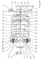
- Fig. 1 In the DE 101 28 076 A1 and in Fig. 1 is a known from the prior art transmission device of a vehicle drive train with a prime mover and an internal combustion engine and an output shown.
- the transmission device is associated with a designed as a hydrostatic device variator for continuously varying a ratio of a transmission device.
- a torque provided by the drive engine is introduced into the transmission device in the region of a transmission input and directed out of the transmission device in the direction of the output in the region of a transmission output shaft.
- the applied torque in the region of the transmission input of the prime mover is introduced via a designed as a ring gear first shaft of a presently designed as a single planet summing planetary gear in the transmission device.
- a so-called power split of the drive torque of the prime mover is performed, wherein the torque is passed from the first shaft of the summation to another shaft on which planet gears are rotatably arranged.
- the planet gears mesh with a second shaft of the summation planetary gear designed as a sun gear, which in the present case is operatively connected to the variator via spur gear toothing.
- the second shaft of the summation planetary gear is coupled to a first shaft of the variator, while the first shaft of the summation planetary gear via the shaft and the gear train is in operative connection with a second shaft of the variator.
- the transmission device is designed with three other planetary gear sets and five frictional shift elements of a gearbox, the frictional shift elements are frictional clutches, while the frictional switching element is a brake.
- the first wave of the Summierplanetengetriebes is rotatably connected to a planet carrier of the first planetary gear set. Furthermore, the further shaft of the summation planetary gear is rotatably coupled to a planet carrier of the second planetary gear set and a ring gear of the first planetary gear set. A sun gear of the first planetary gear set is rotatably connected to a sun gear of the second planetary gear set.
- the planet carrier of the Summierplanetengetriebes thus rotatably connected ring gear of the first planetary gear and turn rotatably connected planet carrier of the second planetary gear set are rotatably connected via the third frictional switching element with a planet carrier of the third planetary gear set.
- the planet carrier of the third planetary gear set is rotatably connected to the transmission output shaft.
- the further shaft of the summation planetary gear is rotatably coupled together with the ring gear of the first planetary gear and the planet carrier of the second planetary gear set with a sun gear of the third planetary, while a ring gear of the third planetary gear set in the closed state the brake rotatably with a gearbox fixed component is in operative connection.
- a ring gear of the second planetary gear set is rotatably connected to the sun gear of the third planetary, while the sun gears of the planetary gear sets are firmly connected to the sun gear of the third planetary gear set with closed second frictional engagement element.
- the above-described transmission device is characterized by the associated hydrostatic device disadvantageously, both by a high space requirement and by high production costs. Furthermore, owing to the cooling and lubricating oil requirement of the hydrostatic unit in the hydraulic supply system of the transmission device and also due to bearing, gear and drag losses in the region of the hydrostatic power path over the entire operating range of the transmission device, the transmission device can be operated undesirably only with reduced efficiency. In addition, the components of the transmission device are exposed due to the variator- or hydrostat Vintage Solutions that adversely affect a lifetime.
- the transmission device is operable at low operating temperatures of the hydrostatic device only after a time-consuming warm-up phase of the hydrostatic device to the desired extent.
- the EP 941 883 A2 discloses a continuously variable transmission device with power split, which takes place in the region of a summation planetary gear (7), wherein a first shaft (9) of the summation planetary gear (7) with a prime mover (1) is operatively engageable, wherein a second shaft (8) of the Summierplanetengetriebes ( 7) for stepless variation of the translation with an electrical machine (6) is connectable, which in turn with an electrical energy source (20 can be coupled.
- the present invention is therefore an object of the invention to provide a space-saving continuously variable transmission device with power split available, with which the aforementioned disadvantages of known from practice continuously variable transmission device in a simple and cost-effective manner are avoidable.
- a first shaft of the Summierplanetengetriebes with a prime mover in operative connection can be brought.
- a second shaft of the Summierplanetengetriebes is connected for stepless variation of the translation with an electric machine, which in turn is coupled to an electric power source.
- the continuously variable transmission device according to the invention Due to the design of the continuously variable transmission device according to the invention with an electric machine for infinitely varying the ratio instead of a variator designed as a hydrostatic device, the continuously variable transmission device according to the invention can be carried out in the radial or in the axial direction with a smaller space requirement compared to the transmission device known from practice. Furthermore, the transmission device according to the invention by the elimination of the hydrostatic unit and its drive system, which includes, among other drive wheels, shafts, bearings and housing parts, also cheaper to produce.
- the continuously variable transmission device according to the invention is compared to the known from practice transmission device also operable with a higher efficiency, since drive power losses due to the elimination of the cooling and lubricating oil demand of the hydrostatic unit in the hydraulic supply system of the transmission device and the concomitant avoidance of storage, gear and Towing losses are reduced in the range of the hydrostatic power path over the entire operating condition of a vehicle.
- Transmission components of the continuously variable transmission device according to the invention are in contrast to the known transmission device due to the elimination of the mechanical and hydraulic vibration excitation by the Hydrostatic unit exposed to lower loads, whereby a lifetime of the transmission device according to the invention is improved.
- the electrical machine coupled to the summation planetary gear train is preferably capable of being operated regeneratively in overrun mode of a vehicle until near a vehicle standstill, and thus a recuperation operation which improves the efficiency of a vehicle drivetrain provided with the gearbox can be represented.
- a running with the continuously variable transmission according to the invention vehicle is operable in comparison to the known from practice transmission device also with higher spontaneity, since the time-consuming warm-up phase prior to commissioning of the hydrostatic device of the known transmission device is not required.
- the electrical energy source to a fuel cell.
- the electrical energy source comprises an electrical machine which can be brought into operative connection with an internal combustion engine
- the electrical machine connected to the summing planetary gear and provided for the stepless change in the ratio of the transmission device can be supplied with electrical energy to the desired extent over a correspondingly long period of time.
- a vehicle designed with the stepless transmission device can be operated without additional mechanical turning unit only by reversing the direction of rotation in the area of the electric machine in a structurally simple and cost-effective manner and with a low space requirement also in the reverse direction.
- the drive machine designed as an electric machine can be electrically coupled to the energy source and preferably also to the electric machine that can be connected to the second shaft of the summation planetary gearbox, whereby electrical energy can be exchanged between the electrical machines depending on the prevailing operating state of a vehicle drive train designed with the continuously variable transmission device according to the invention and a vehicle powertrain is operable with high efficiency.
- prime mover is designed as an internal combustion engine, it is possible in a simple manner to couple the electrical machine to the electrical energy source and to design the prime mover and the internal combustion engine, which can be brought into operative connection with the electric machine, as a structural unit. Alternatively, however, there is also the possibility that the prime mover and the internal combustion engine which can be brought into operative connection with the electric machine of the electrical energy source are separate internal combustion engines.
- the prime mover can be connected to the first shaft of the summation planetary gear via a frictionally engaged shift element, the prime mover can be disconnected from the first shaft of the summation planetary gear depending on the operating state, thus avoiding unwanted introduction of drag torques generated by the region of the drive machine into the transmission device in a simple manner.
- the electrical machines are arranged at least partially axially adjacent to each other and / or radially into one another.
- An inexpensive further embodiment of the continuously variable transmission device according to the invention has a common cooling circuit of the electrical machines.
- the electric machines can each be coupled to the summation planetary gearbox via a gear, an adaptation of the rotor speeds to the optimum operating ranges of the electric machine can be realized in a simple and cost-effective manner.
- the electrical energy source to an electrical storage device which is not required for driving an electric machine or to supply a vehicle electrical system, produced during operation electrical energy, while further improving the efficiency in the field of electrical Memory device is cacheable.
- a further embodiment of the stepless transmission device according to the invention characterized by a high power density comprises a gearbox which is connected to the third shaft of the summation planetary gear and which comprises a plurality of planetary gear devices, the shafts of which represent different transmission ranges within which the transmission in each case via the Summierplanetengetriebe and thus connected electrical machine is infinitely variable, are preferably connected to each other via preferably frictional switching elements.
- the first wave of the Summierplanetengetriebes is connected in another also characterized by a high power density embodiment of the continuously variable transmission according to the invention with a first shaft of a first planetary gear device of the gearbox, while the third wave of the summation planetary gear with a second shaft of the first planetary gear device and with a first wave of a second planetary gear device of the gearbox is connected.
- FIG. 2 is a schematic diagram of a first embodiment of the transmission device 1 according to the invention shown, in which the first shaft 8 of the Summierplanetengetriebes 9 is operatively connected to the executable as an electric machine drive machine 3 and an electric machine 36 with the shaft 12 of the summation planetary gear 9 for continuously varying the translation of Transmission device 1 is connected to an electric machine 36.
- the electric machine 36 is operable both by motor and generator.
- the electric machine 36 is in turn coupled via an electrical connection 39 to an electrical energy source 38, which in the present case comprises a fuel cell 49, in the region of which the electrical energy required for the motor operation of the electric machine 36 can be generated.
- the further shaft 10 of the Summierplaninetgetriebes 9 can be brought into operative connection with the output 4 and the prime mover 3 is preferably also supplied from the power source 38 with energy.
- the rotational speed of the second shaft 12 of the summation planetary gear 9 is varied by the motor or regenerative operation of the electric machine 36 and thus the ratio of the continuously variable transmission device 1 continuously changed, whereby each provided via the engine 3 available drive torque in accordance with the changed height on the Another wave 10 or the third wave of the Summierplanetengetriebes 9 can be forwarded in the direction of the output.
- Fig. 3 shows a further partial schematic representation of a second embodiment of the inventive continuously variable transmission device 1 with power split, which takes place in the area of the summation planetary gear 9.
- the first shaft 8 of the summation planetary gear is in operative connection with the drive machine 3.
- the second shaft 12 of the summation planetary gear 9 is connected to the electric machine 36 for infinitely varying the ratio of the transmission device 1.
- the electric machine 36 is in turn coupled to an electrical energy source 38 comprising an electric machine 37, the electric machine 37 in the present case being in operative connection with the drive machine 3 in the region of the transmission input 6.
- the drive machine 3 is designed as an internal combustion engine whose drive torque is introduced via the shaft 8 of the summation planetary gear 9 in the transmission device 1.
- a portion of the drive torque of the drive machine 3 is used to generate electrical energy, which is supplied via an electrical connection 39 of the electric machine 36 during a motor operation of the electric machine 36.
- the electrical energy generated there via the electrical connection 39 of the electric machine 37 of the electric power source 38 can be supplied and during motor operation of the electric machine 37 as torque in the power flow between the drive machine 3 and the Summierplanetengetriebe 8 preferably for the drive of a vehicle can be introduced.
- the electric machine 37 via a separate from the first shaft 8 of the summation 9 executed shaft 40 with the also designed as an internal combustion engine drive unit 3 and electrically coupled to the electrical machine 36 to the extent described above.
- the electrical energy source 38 comprises an electrical storage device 41, in the region of which electrical energy generated by the electric machines 36 and 37 can be temporarily stored and via which both the electric machine 36 and the electric machine 37 can be supplied with electrical energy.
- Fig. 5 shows a training of in Fig. 4 shown drive system in which the drive machine 3 is designed as an electric machine 37.
- the electric machine 37 of the electric power source 38 is in the present case connected to an internal combustion engine 42, thus generating electrical energy in the region in which the electric machine 37 is driven by the internal combustion engine and at the same time that the electric machine 37 is operating.
- the electrical energy generated in the region of the electric machine 37 can be supplied to the electrical machine 36 via the electrical connection 39.
- the electric machine 37 of the electrical energy source 38 is connected via a further electrical connection 43 to the drive machine 3 designed as an electrical machine.
- the prime mover 3 and the electric machine 36 are coupled to each other via an additional electrical connection 44.
- drive system can be generated via the internal combustion engine 42 current, which is convertible in the drive motor 3 in a drive torque.
- the electrical current generated in the region of the electric machine 37 can be used to display the motor operation of the electric machine 36.
- FIG. 4 A detailed presentation of in Fig. 4 illustrated in principle embodiment of the transmission device 1 according to the invention Fig. 6 in which the electric machine 37 of the electric power source 38 is connected via a gear 45 to the first shaft 8 of the summing planetary gear 9 designed as a ring gear, with which a rotor speed can be adapted to the optimum operating range of the electric machine 37.
- the electric machine 36 is coupled via a further gear 46 with the second shaft 12 of the summation planetary gear 9 designed as a sun gear and can also be operated in an optimized manner.
- the electric machines 36 and 37 of the transmission device 1 according to Fig. 6 are arranged axially side by side, whereby the transmission device 1 is characterized in the radial direction by a small space requirement.
- a separating clutch 47 is provided between the electric machine 37 and the drive machine 3 designed as an internal combustion engine in order to connect the drive machine 3 to the transmission device 1 as a function of operation or to decouple it from this.
- FIG. 7 shown further embodiment of the continuously variable transmission device 1 according to the invention corresponds to the arrangement of the electric machines 36 and 37 substantially in Fig. 6 Therefore, below, essentially only the differences are discussed and with respect to the further operation of the transmission device 1 according to Fig. 7 Reference is made to the above description.
- the electric machine 37 is arranged radially inside the electric machine 36, which is why the transmission device 1 in the radial direction requires a larger space than the transmission device 1 according to Fig. 6 having.
- the transmission device 1 according to Fig. 7 In the axial direction, the transmission device 1 according to Fig. 7 However, by a smaller space requirement than the transmission device 1 according to Fig. 6 characterized.
- Fig. 8 shows a development of the transmission device 1 according to Fig. 7 in which the electric machine 36 and the electric machine 37 have a common cooling circuit 48.
- the integrated arrangement of the electrical machines 36 and 37 is used in addition to the axial space reduction to a cost-effective representation of common functions and facilities of the electric machines 36 and 37, wherein the common cooling circuit 48 by an adapted arrangement of the stators 36A, 37A and rotors 36B, 37B of electric machines 36 and 37 is enabled.
- FIG. 9 illustrated further embodiment of the transmission device 1 according to the invention is characterized by a further arrangement of the electric machines 36 and 37 to each other and with respect to the summation planetary gear 9, wherein the electric machine 37 is disposed axially in front of the summation planetary gear 9 and the electric machine 36, the Summierplanetengetriebe 9 radially surrounds ,
- the arrangement of the electric machine 36 represents a comparatively space-saving realization of a maximum diameter of the rotor 36B of the electric machine 36 in the space between the planetary roller or the Summierplanetengetriebe 9 and a transmission housing 51 of the transmission device 1.
- the stator 36A of the electric machine 36 is simple Way in the gear housing 51 can be arranged, whereby storage and cooling functions, such as heat dissipation and integration of cooling channels and the like in the transmission housing 51 are displaced.
- the reverse driving operation is made possible by appropriate control of the electric machine 37 and / or the electric machine 36, wherein the necessary electric drive power from the electric machine 37 during a regenerative operation or another generator, as in the transmission device 1 according to Fig. 5 , in the drive system in conjunction with another internal combustion engine or from an electrical storage system, such as a battery, is adjustable.
- the reverse drive operation is by blocking the summing planetary gear 9, d. H. in closed frictional engagement elements 23 and 24, in conjunction with simultaneously closed frictional engagement element 21 or closed frictional engagement element 22 in motor operation of the electric machine 36 with reduced output torque feasible.
- Fig. 10 shows a detailed representation of the in Fig. 4 shown powertrain system in which the electric machine 37 is not arranged in the region of the transmission input 6 and is not directly connected to this.
- the transmission device 1 the full transmission functionality is also available during a reverse drive when the transmission input 6, for example, during a corresponding operation of the engine 3, ie with the internal combustion engine, rotatably held at the output and a corresponding output torque from the electric machine 36 is available is provided.
- illustrated transmission structure of the transmission device 1 according to the invention is in each case coupled to the electric machine 37, which is connected to the designed as an internal combustion engine drive machine 3 and the first shaft 8 of the summation planetary gear 9.
- the transmission device 1 is in addition to the Summierplanetengetriebe 9 in each case with the three other planetary gear sets 18, 19 and 20 designed to provide in conjunction with the frictional switching elements 21 to 25 several translation areas available.
- the transmission device 1 it is also possible to design the transmission device 1 with a smaller number of planetary gear sets and frictional shift elements, in which case a reduced number of transmission ranges is available.
- the planetary gear sets 18, 19 and 20 of the gearbox 50 by other suitable transmission elements, by means of which in combination with switching elements different transmission ranges can be displayed.
- the electric machines 36 and 37 of the transmission device 1 according to the invention are each incorporated in such an electronic control system of the transmission device 1, that in the operating states of the transmission device 1, during which the sun gear 12 and the second shaft of the Summierplanetengetriebes 9 for continuously changing the ratio of the transmission device. 1 is to be driven within a transmission range, the electric machine 37 is operated as a generator and outputs electrical power to the motor-driven electric machine 36.
- the electric driving power required for the operation of the electric machine 36 may alternatively or additionally be provided from an electric storage system such as the electric storage device 41.
- the electric machine 36 In operating states of the transmission device 1, during which the sun gear 12 of the Summierplanetsgetriebes 9 to a certain speed is braked, the electric machine 36 is operated as a generator and the electrical power generated in the electrical machine 36, for example, to the electrical storage device 41, an electrical consumer system of the vehicle or the motor-driven electric machine 37 discharged.
Landscapes
- Engineering & Computer Science (AREA)
- Mechanical Engineering (AREA)
- General Engineering & Computer Science (AREA)
- Chemical & Material Sciences (AREA)
- Combustion & Propulsion (AREA)
- Transportation (AREA)
- Arrangement Of Transmissions (AREA)
- Structure Of Transmissions (AREA)
- Hybrid Electric Vehicles (AREA)
- Electric Propulsion And Braking For Vehicles (AREA)
Claims (10)
- Dispositif de transmission à variation continue (1) avec division de puissance, qui a lieu dans la région d'un engrenage planétaire sommateur (9), un premier arbre (8) de l'engrenage planétaire sommateur (9) pouvant être amené en liaison fonctionnelle avec une machine motrice (3), un deuxième arbre (12) de l'engrenage planétaire sommateur (9) pouvant être connecté à une machine électrique (36) en vue de faire varier la démultiplication de manière continue, laquelle machine électrique peut à son tour être accouplée à une source d'énergie électrique (38), caractérisé en ce que la machine motrice (3) est réalisée sous forme de machine électrique (36, 37) et la machine motrice (3) réalisée sous forme de machine électrique est accouplée électriquement à la source d'énergie (38) et à la machine électrique (36) pouvant être connectée au deuxième arbre (12) de l'engrenage planétaire sommateur (9), un troisième arbre (10) de l'engrenage planétaire sommateur (9) pouvant être accouplé à une prise de force (4) et le troisième arbre (10) de l'engrenage planétaire sommateur (9) étant connecté à une transmission à changement de vitesses (50) qui comprend plusieurs systèmes d'engrenages planétaires (18, 19, 20), dont les arbres peuvent être connectés les uns aux autres par le biais d'éléments de commutation (21 à 24) pour produire différentes plages de démultiplication, à l'intérieur desquelles la démultiplication peut être variée en continu à chaque fois par le biais de l'engrenage planétaire sommateur (9) et de la machine électrique (36) connectée à celui-ci.
- Dispositif de transmission à variation continue selon la revendication 1, caractérisé en ce que la source d'énergie électrique (38) présente une pile à combustible (49).
- Dispositif de transmission à variation continue selon la revendication 1 ou 2, caractérisé en ce que la source d'énergie électrique (38) comprend une machine électrique (37) qui peut être amenée en liaison fonctionnelle avec une machine motrice (3).
- Dispositif de transmission à variation continue selon l'une quelconque des revendications 1 à 3, caractérisé en ce que la source d'énergie électrique (38) présente un dispositif accumulateur électrique (41).
- Dispositif de transmission à variation continue selon l'une quelconque des revendications 1 à 4, caractérisé en ce que la machine motrice (3) peut être connectée par le biais d'un élément de commutation à engagement par friction (47) au premier arbre (8) de l'engrenage planétaire sommateur (9).
- Dispositif de transmission à variation continue selon l'une quelconque des revendications 1 à 5, caractérisé en ce que le premier arbre (8) de l'engrenage planétaire sommateur (9) est une couronne dentée.
- Dispositif de transmission à variation continue selon l'une quelconque des revendications 1 à 6, caractérisé en ce que le deuxième arbre (12) de l'engrenage planétaire sommateur (9) est réalisé sous forme de roue solaire.
- Dispositif de transmission à variation continue selon l'une quelconque des revendications 1 à 7, caractérisé en ce que le troisième arbre (10) de l'engrenage planétaire sommateur (9) est réalisé sous forme de porte-satellites.
- Dispositif de transmission à variation continue selon la revendication 8, caractérisé en ce que les éléments de commutation (21 à 24) sont réalisés sous forme d'éléments de commutation à engagement par friction (21 à 24).
- Dispositif de transmission à variation continue selon la revendication 9, caractérisé en ce que le troisième arbre (10) de l'engrenage planétaire sommateur (9) est connecté à un premier arbre (28) d'un premier système d'engrenage planétaire (18) de la transmission à changement de vitesses (50) et à un premier arbre (27) d'un deuxième système d'engrenage planétaire (19) de la transmission à changement de vitesses (50).
Applications Claiming Priority (2)
| Application Number | Priority Date | Filing Date | Title |
|---|---|---|---|
| DE102010003941A DE102010003941A1 (de) | 2010-04-14 | 2010-04-14 | Stufenlose Getriebevorrichtung mit Leistungsverzweigung |
| PCT/EP2011/052093 WO2011128125A1 (fr) | 2010-04-14 | 2011-02-14 | Dispositif de transmission à action progressive avec partage de puissance |
Publications (2)
| Publication Number | Publication Date |
|---|---|
| EP2558746A1 EP2558746A1 (fr) | 2013-02-20 |
| EP2558746B1 true EP2558746B1 (fr) | 2014-01-15 |
Family
ID=43857997
Family Applications (1)
| Application Number | Title | Priority Date | Filing Date |
|---|---|---|---|
| EP11705187.0A Active EP2558746B1 (fr) | 2010-04-14 | 2011-02-14 | Dispositif de transmission à variation continue avec division de puissance |
Country Status (5)
| Country | Link |
|---|---|
| US (1) | US8777790B2 (fr) |
| EP (1) | EP2558746B1 (fr) |
| CN (1) | CN102844588B (fr) |
| DE (1) | DE102010003941A1 (fr) |
| WO (1) | WO2011128125A1 (fr) |
Families Citing this family (35)
| Publication number | Priority date | Publication date | Assignee | Title |
|---|---|---|---|---|
| EP2795159B1 (fr) * | 2011-12-23 | 2019-06-26 | Volvo Construction Equipment AB | Transmission variable continue et machine de travail comprenant une transmission à réglage continu |
| DE102012204477B4 (de) | 2012-03-21 | 2023-05-11 | Zf Friedrichshafen Ag | Getriebevorrichtung mit wenigstens einem elektrischen Variator zum stufenlosen Variieren einer Übersetzung und mit Leistungsverzweigung |
| DE102012216277B4 (de) * | 2012-09-13 | 2022-07-14 | Zf Friedrichshafen Ag | Getriebevorrichtung mit einer Planetengetriebeeinrichtung |
| DE102013204747A1 (de) * | 2013-03-19 | 2014-09-25 | Zf Friedrichshafen Ag | Getriebevorrichtung mit sekundär gekoppelter Leistungsverzweigung |
| US10670124B2 (en) | 2013-12-31 | 2020-06-02 | Deere & Company | Multi-mode infinitely variable transmission |
| US10655710B2 (en) | 2013-12-31 | 2020-05-19 | Deere & Company | Multi-mode infinitely variable transmission that provides seamless shifting |
| US9944163B2 (en) * | 2014-04-09 | 2018-04-17 | Deere & Company | Multi-mode power trains |
| US10647193B2 (en) | 2014-04-09 | 2020-05-12 | Deere & Company | Multi-mode power trains |
| US10738868B2 (en) | 2014-04-09 | 2020-08-11 | Deere & Company | Multi-mode powertrains |
| EP3366948B1 (fr) | 2014-06-13 | 2021-01-27 | Caterpillar Inc. | Transmission assistée par variateur et procede de fonctionnement correspondant |
| CN104074937B (zh) * | 2014-06-18 | 2016-04-06 | 青岛大学 | 一种纯机械功率分流装置 |
| DE102015226211A1 (de) * | 2015-12-21 | 2017-06-22 | Zf Friedrichshafen Ag | Getriebe für ein Kraftfahrzeug |
| DE102016204727A1 (de) * | 2016-03-22 | 2017-09-28 | Zf Friedrichshafen Ag | Stufenlos leistungsverzweigtes Getriebe mit mindestens einem Fahrbereich |
| DE102016204725A1 (de) * | 2016-03-22 | 2017-09-28 | Zf Friedrichshafen Ag | Stufenlos leistungsverzweigtes Getriebe mit mindestens einem Fahrbereich |
| IT201600071646A1 (it) | 2016-07-08 | 2018-01-08 | Nuovo Pignone Tecnologie Srl | Trasmissione a velocita' variabile e sistema che la utilizza |
| US10619711B2 (en) | 2017-04-12 | 2020-04-14 | Deere & Company | Infinitely variable transmission with power reverser |
| DE102017222596B4 (de) * | 2017-12-13 | 2019-07-04 | Zf Friedrichshafen Ag | Stufenlos leistungsverzweigtes Getriebe |
| US11052747B2 (en) | 2018-05-04 | 2021-07-06 | Deere & Company | Multi-mode powertrains |
| US11091018B2 (en) | 2018-05-11 | 2021-08-17 | Deere & Company | Powertrain with variable vertical drop distance |
| DE102018214037A1 (de) * | 2018-08-20 | 2020-02-20 | Zf Friedrichshafen Ag | Stufenlos leistungsverzweigtes Getriebe sowie Verfahren zum Betreiben eines stufenlos leistungsverzweigten Getriebes |
| US10975959B2 (en) | 2019-04-01 | 2021-04-13 | Deere & Company | Transmission clutch braking control system |
| US11137052B2 (en) | 2019-08-29 | 2021-10-05 | Deere & Company | Transmission assembly with integrated CVP |
| US11351983B2 (en) | 2019-10-31 | 2022-06-07 | Deere & Company | Power control system with transmission transient boost function |
| US11846085B2 (en) | 2020-02-17 | 2023-12-19 | Deere & Company | Energy management system for a hybrid vehicle with an electrically powered hydraulic system |
| US11325459B2 (en) | 2020-10-09 | 2022-05-10 | Deere & Company | Low profile transmission assembly with integrated CVP |
| US11613246B2 (en) | 2021-01-21 | 2023-03-28 | Deere & Company | Power control system with engine throttle shift function |
| US11628822B2 (en) | 2021-02-09 | 2023-04-18 | Deere & Company | Power control system with stall prevention clutch modulation function |
| US11299141B1 (en) | 2021-02-10 | 2022-04-12 | Deere & Company | System for multi-layer braking and retardation in a work vehicle |
| US11820361B2 (en) | 2021-11-30 | 2023-11-21 | Deere & Company | Transmission assembly with electrical machine unit for improved shift quality |
| US11585412B1 (en) | 2021-12-22 | 2023-02-21 | Deere & Company | Electronically-variable, dual-path power shift transmission for work vehicles |
| US11607948B1 (en) | 2021-12-22 | 2023-03-21 | Deere & Company | Electronically-variable power shift transmission for work vehicles |
| DE102022204881A1 (de) | 2022-05-17 | 2023-11-23 | Zf Friedrichshafen Ag | Leistungsverzweigungsgetriebe |
| US11913528B1 (en) | 2022-10-28 | 2024-02-27 | Deere & Company | Multi-mode continuously variable transmission assembly with drop set arrangement |
| DE102022212547B4 (de) * | 2022-11-24 | 2025-04-17 | Zf Friedrichshafen Ag | Leistungsstrang für eine Arbeitsmaschine und Arbeitsmaschine |
| DE102023202276B3 (de) * | 2023-03-14 | 2024-07-25 | Zf Friedrichshafen Ag | Antriebsstrang für ein Kraftfahrzeug |
Family Cites Families (17)
| Publication number | Priority date | Publication date | Assignee | Title |
|---|---|---|---|---|
| DE3935228A1 (de) | 1989-10-23 | 1991-04-25 | Forschungsgesellschaft Kraftfa | Antriebsvorrichtung |
| DE4124479C2 (de) | 1991-07-24 | 2002-05-16 | Bayerische Motoren Werke Ag | Hybridantrieb, insbesondere für Fahrzeuge |
| JP3047792B2 (ja) | 1995-10-18 | 2000-06-05 | トヨタ自動車株式会社 | ハイブリッド駆動装置 |
| DE19810374B4 (de) * | 1998-03-10 | 2013-05-02 | Bayerische Motoren Werke Aktiengesellschaft | Hybridantrieb für ein Kraftfahrzeug |
| DE19841828C2 (de) * | 1998-09-12 | 2002-05-29 | Daimler Chrysler Ag | Hybridantrieb, insbesondere für Fahrzeuge |
| DE10128076A1 (de) | 2001-06-09 | 2002-12-12 | Zahnradfabrik Friedrichshafen | Leistungsverzweigungsgetriebe |
| DE10358114A1 (de) * | 2002-12-23 | 2004-07-01 | Luk Lamellen Und Kupplungsbau Beteiligungs Kg | Getriebe mit stufenlos verstellbarer Übersetzung, mit oder ohne Leistungsverzweigung sowie mit und ohne E-Maschine |
| CN102518769B (zh) * | 2005-07-23 | 2015-04-15 | 卢克摩擦片和离合器两合公司 | 具有变速比可无级调节的多个变速比范围的功率分流式变速器 |
| DE102005039461A1 (de) | 2005-08-20 | 2007-03-15 | Daimlerchrysler Ag | Hybrider Antriebsstrang eines Kraftfahrzeugs und Verfahren zum Betrieb eines hybriden Antriebsstrangs |
| DE102005044181A1 (de) | 2005-09-15 | 2007-04-19 | Deere & Company, Moline | Antriebssystem für ein Fahrzeug und ein landwirtschaftliches Nutzfahrzeug |
| JP4281764B2 (ja) * | 2006-08-03 | 2009-06-17 | トヨタ自動車株式会社 | 車両用変速機 |
| US7704176B2 (en) * | 2007-01-31 | 2010-04-27 | Gm Global Technology Operations, Inc. | Electrically variable transmission device using multiple pairings of electrical machines |
| DE102007022774A1 (de) | 2007-05-15 | 2008-11-20 | Zf Friedrichshafen Ag | Zugkraftunterbrechungsfreies Getriebe mit einem elektrodynamischen Anfahrelement |
| DE102007051473A1 (de) | 2007-10-27 | 2009-04-30 | Bayerische Motoren Werke Aktiengesellschaft | Hybridfahrzeug |
| JP5018445B2 (ja) * | 2007-12-13 | 2012-09-05 | トヨタ自動車株式会社 | 車両用動力伝達装置の制御装置 |
| JP5298573B2 (ja) * | 2008-03-04 | 2013-09-25 | トヨタ自動車株式会社 | 車両用動力伝達装置の制御装置 |
| DE102009019485A1 (de) | 2008-12-09 | 2010-06-10 | Isatec Gmbh | Antriebsstrang mit einem ersten Elektromotor und einem Planetengetriebe sowie Windenergieanlagen, Gasturbinen und Wasserturbinen und Fahrzeuge, die diesen Antriebsstrang aufweisen |
-
2010
- 2010-04-14 DE DE102010003941A patent/DE102010003941A1/de not_active Withdrawn
-
2011
- 2011-02-14 CN CN201180018731.3A patent/CN102844588B/zh not_active Expired - Fee Related
- 2011-02-14 WO PCT/EP2011/052093 patent/WO2011128125A1/fr not_active Ceased
- 2011-02-14 EP EP11705187.0A patent/EP2558746B1/fr active Active
- 2011-02-14 US US13/637,400 patent/US8777790B2/en active Active
Also Published As
| Publication number | Publication date |
|---|---|
| EP2558746A1 (fr) | 2013-02-20 |
| CN102844588A (zh) | 2012-12-26 |
| US20130023370A1 (en) | 2013-01-24 |
| WO2011128125A1 (fr) | 2011-10-20 |
| DE102010003941A1 (de) | 2011-10-20 |
| CN102844588B (zh) | 2015-05-13 |
| US8777790B2 (en) | 2014-07-15 |
Similar Documents
| Publication | Publication Date | Title |
|---|---|---|
| EP2558746B1 (fr) | Dispositif de transmission à variation continue avec division de puissance | |
| EP2115320B1 (fr) | Train complexe à deux groupes planétaires multi-étagé | |
| AT520075B1 (de) | Drehmomentübertragungsvorrichtung sowie Verfahren zu deren Betrieb | |
| DE69909908T2 (de) | Elektro-mechanischer Antriebsstrang | |
| DE102005045320B4 (de) | Elektrisch verstellbares Getriebe mit entkoppeltem Verbrennungsmotor, der im Rückwärtsgang lädt, und Antriebsstrangmit einem derartigen Getriebe | |
| DE102015221499B4 (de) | Antriebsanordnung für ein Hybridfahrzeug und Antriebsstrang mit einer solchen Antriebsanordnung | |
| DE102006044500B4 (de) | Elektromechanisches Getriebe mit Eingangsverzweigung, zwei festen Drehzahlverhältnissen und einer Betriebsart | |
| WO2009024162A1 (fr) | Système d'entraînement hybride à deux transmissions partielles | |
| DE10140424A1 (de) | Automatisch schaltbares Fahrzeuggetriebe | |
| WO2014122026A1 (fr) | Dispositif de superposition de couples pour motorisation hybride et procédé de fonctionnement d'une telle motorisation hybride | |
| DE102007001840A1 (de) | Hybridantrieb, insbesondere für ein Kraftfahrzeug | |
| DE102005022011A1 (de) | Antriebsstrang für ein Kraftfahrzeug mit einer Brennkraftmaschine und einem elektrischen Antriebsaggregat | |
| EP3448704A1 (fr) | Boîte de vitesse pour une propulsion hybride, procédé de commande d'une telle boîte de vitesses, produit-programme informatique, dispositif de commande et/ou de régulation et propulsion hybride | |
| DE102005039461A1 (de) | Hybrider Antriebsstrang eines Kraftfahrzeugs und Verfahren zum Betrieb eines hybriden Antriebsstrangs | |
| DE102006040628B4 (de) | Hybrides elektromechanisches Getriebe | |
| DE102006054364A1 (de) | Elektromechanisches Getriebe mit sechs Gängen und Verfahren zum Umkonstruieren eines Getriebes | |
| EP3100889A1 (fr) | Boîte de vitesses d'un véhicule automobile, et groupe motopropulseur pour un véhicule hybride équipé d'une telle boîte de vitesses | |
| DE102016200644B4 (de) | Kompaktes Mehrstufengetriebe | |
| DE102019200966B4 (de) | Leistungsverzweigtes Kraftfahrzeuggetriebe | |
| DE102017219998A1 (de) | Stufenloses Leistungsverzweigungsgetriebe mit zwei Fahrbereichen | |
| DE102020203774A1 (de) | Hybridgetriebe mit zwei Planetenradsätzen | |
| DE102021206520B4 (de) | Gangvorwahlfrei lastschaltbares Hybridgetriebe mit einfachem Aufbau | |
| WO2014075843A2 (fr) | Boîte de vitesses hybridée de véhicule à moteur | |
| EP3290247B1 (fr) | Groupe motopropulseur hybride pour véhicule automobile et son procédé de fonctionnement | |
| DE102020203773A1 (de) | Mehrgängiges Planetengetriebe |
Legal Events
| Date | Code | Title | Description |
|---|---|---|---|
| PUAI | Public reference made under article 153(3) epc to a published international application that has entered the european phase |
Free format text: ORIGINAL CODE: 0009012 |
|
| 17P | Request for examination filed |
Effective date: 20120917 |
|
| AK | Designated contracting states |
Kind code of ref document: A1 Designated state(s): AL AT BE BG CH CY CZ DE DK EE ES FI FR GB GR HR HU IE IS IT LI LT LU LV MC MK MT NL NO PL PT RO RS SE SI SK SM TR |
|
| DAX | Request for extension of the european patent (deleted) | ||
| GRAP | Despatch of communication of intention to grant a patent |
Free format text: ORIGINAL CODE: EPIDOSNIGR1 |
|
| INTG | Intention to grant announced |
Effective date: 20131022 |
|
| GRAS | Grant fee paid |
Free format text: ORIGINAL CODE: EPIDOSNIGR3 |
|
| GRAA | (expected) grant |
Free format text: ORIGINAL CODE: 0009210 |
|
| AK | Designated contracting states |
Kind code of ref document: B1 Designated state(s): AL AT BE BG CH CY CZ DE DK EE ES FI FR GB GR HR HU IE IS IT LI LT LU LV MC MK MT NL NO PL PT RO RS SE SI SK SM TR |
|
| REG | Reference to a national code |
Ref country code: GB Ref legal event code: FG4D Free format text: NOT ENGLISH Ref country code: CH Ref legal event code: EP |
|
| REG | Reference to a national code |
Ref country code: AT Ref legal event code: REF Ref document number: 649988 Country of ref document: AT Kind code of ref document: T Effective date: 20140215 |
|
| REG | Reference to a national code |
Ref country code: IE Ref legal event code: FG4D Free format text: LANGUAGE OF EP DOCUMENT: GERMAN |
|
| REG | Reference to a national code |
Ref country code: DE Ref legal event code: R096 Ref document number: 502011002050 Country of ref document: DE Effective date: 20140227 |
|
| REG | Reference to a national code |
Ref country code: NL Ref legal event code: VDEP Effective date: 20140115 |
|
| REG | Reference to a national code |
Ref country code: LT Ref legal event code: MG4D |
|
| PG25 | Lapsed in a contracting state [announced via postgrant information from national office to epo] |
Ref country code: IS Free format text: LAPSE BECAUSE OF FAILURE TO SUBMIT A TRANSLATION OF THE DESCRIPTION OR TO PAY THE FEE WITHIN THE PRESCRIBED TIME-LIMIT Effective date: 20140515 Ref country code: LT Free format text: LAPSE BECAUSE OF FAILURE TO SUBMIT A TRANSLATION OF THE DESCRIPTION OR TO PAY THE FEE WITHIN THE PRESCRIBED TIME-LIMIT Effective date: 20140115 Ref country code: NO Free format text: LAPSE BECAUSE OF FAILURE TO SUBMIT A TRANSLATION OF THE DESCRIPTION OR TO PAY THE FEE WITHIN THE PRESCRIBED TIME-LIMIT Effective date: 20140415 |
|
| PG25 | Lapsed in a contracting state [announced via postgrant information from national office to epo] |
Ref country code: NL Free format text: LAPSE BECAUSE OF FAILURE TO SUBMIT A TRANSLATION OF THE DESCRIPTION OR TO PAY THE FEE WITHIN THE PRESCRIBED TIME-LIMIT Effective date: 20140115 Ref country code: CY Free format text: LAPSE BECAUSE OF FAILURE TO SUBMIT A TRANSLATION OF THE DESCRIPTION OR TO PAY THE FEE WITHIN THE PRESCRIBED TIME-LIMIT Effective date: 20140115 Ref country code: PT Free format text: LAPSE BECAUSE OF FAILURE TO SUBMIT A TRANSLATION OF THE DESCRIPTION OR TO PAY THE FEE WITHIN THE PRESCRIBED TIME-LIMIT Effective date: 20140515 Ref country code: FI Free format text: LAPSE BECAUSE OF FAILURE TO SUBMIT A TRANSLATION OF THE DESCRIPTION OR TO PAY THE FEE WITHIN THE PRESCRIBED TIME-LIMIT Effective date: 20140115 Ref country code: SE Free format text: LAPSE BECAUSE OF FAILURE TO SUBMIT A TRANSLATION OF THE DESCRIPTION OR TO PAY THE FEE WITHIN THE PRESCRIBED TIME-LIMIT Effective date: 20140115 Ref country code: ES Free format text: LAPSE BECAUSE OF FAILURE TO SUBMIT A TRANSLATION OF THE DESCRIPTION OR TO PAY THE FEE WITHIN THE PRESCRIBED TIME-LIMIT Effective date: 20140115 |
|
| BERE | Be: lapsed |
Owner name: ZF FRIEDRICHSHAFEN A.G. Effective date: 20140228 |
|
| PG25 | Lapsed in a contracting state [announced via postgrant information from national office to epo] |
Ref country code: HR Free format text: LAPSE BECAUSE OF FAILURE TO SUBMIT A TRANSLATION OF THE DESCRIPTION OR TO PAY THE FEE WITHIN THE PRESCRIBED TIME-LIMIT Effective date: 20140115 Ref country code: RS Free format text: LAPSE BECAUSE OF FAILURE TO SUBMIT A TRANSLATION OF THE DESCRIPTION OR TO PAY THE FEE WITHIN THE PRESCRIBED TIME-LIMIT Effective date: 20140115 Ref country code: LV Free format text: LAPSE BECAUSE OF FAILURE TO SUBMIT A TRANSLATION OF THE DESCRIPTION OR TO PAY THE FEE WITHIN THE PRESCRIBED TIME-LIMIT Effective date: 20140115 |
|
| REG | Reference to a national code |
Ref country code: CH Ref legal event code: PL |
|
| REG | Reference to a national code |
Ref country code: DE Ref legal event code: R097 Ref document number: 502011002050 Country of ref document: DE |
|
| PG25 | Lapsed in a contracting state [announced via postgrant information from national office to epo] |
Ref country code: LI Free format text: LAPSE BECAUSE OF NON-PAYMENT OF DUE FEES Effective date: 20140228 Ref country code: CZ Free format text: LAPSE BECAUSE OF FAILURE TO SUBMIT A TRANSLATION OF THE DESCRIPTION OR TO PAY THE FEE WITHIN THE PRESCRIBED TIME-LIMIT Effective date: 20140115 Ref country code: RO Free format text: LAPSE BECAUSE OF FAILURE TO SUBMIT A TRANSLATION OF THE DESCRIPTION OR TO PAY THE FEE WITHIN THE PRESCRIBED TIME-LIMIT Effective date: 20140115 Ref country code: CH Free format text: LAPSE BECAUSE OF NON-PAYMENT OF DUE FEES Effective date: 20140228 Ref country code: DK Free format text: LAPSE BECAUSE OF FAILURE TO SUBMIT A TRANSLATION OF THE DESCRIPTION OR TO PAY THE FEE WITHIN THE PRESCRIBED TIME-LIMIT Effective date: 20140115 Ref country code: EE Free format text: LAPSE BECAUSE OF FAILURE TO SUBMIT A TRANSLATION OF THE DESCRIPTION OR TO PAY THE FEE WITHIN THE PRESCRIBED TIME-LIMIT Effective date: 20140115 Ref country code: MC Free format text: LAPSE BECAUSE OF FAILURE TO SUBMIT A TRANSLATION OF THE DESCRIPTION OR TO PAY THE FEE WITHIN THE PRESCRIBED TIME-LIMIT Effective date: 20140115 |
|
| PLBE | No opposition filed within time limit |
Free format text: ORIGINAL CODE: 0009261 |
|
| REG | Reference to a national code |
Ref country code: FR Ref legal event code: ST Effective date: 20141031 |
|
| STAA | Information on the status of an ep patent application or granted ep patent |
Free format text: STATUS: NO OPPOSITION FILED WITHIN TIME LIMIT |
|
| PG25 | Lapsed in a contracting state [announced via postgrant information from national office to epo] |
Ref country code: PL Free format text: LAPSE BECAUSE OF FAILURE TO SUBMIT A TRANSLATION OF THE DESCRIPTION OR TO PAY THE FEE WITHIN THE PRESCRIBED TIME-LIMIT Effective date: 20140115 Ref country code: SK Free format text: LAPSE BECAUSE OF FAILURE TO SUBMIT A TRANSLATION OF THE DESCRIPTION OR TO PAY THE FEE WITHIN THE PRESCRIBED TIME-LIMIT Effective date: 20140115 |
|
| REG | Reference to a national code |
Ref country code: IE Ref legal event code: MM4A |
|
| 26N | No opposition filed |
Effective date: 20141016 |
|
| PG25 | Lapsed in a contracting state [announced via postgrant information from national office to epo] |
Ref country code: IE Free format text: LAPSE BECAUSE OF NON-PAYMENT OF DUE FEES Effective date: 20140214 Ref country code: FR Free format text: LAPSE BECAUSE OF NON-PAYMENT OF DUE FEES Effective date: 20140317 Ref country code: BE Free format text: LAPSE BECAUSE OF NON-PAYMENT OF DUE FEES Effective date: 20140228 |
|
| REG | Reference to a national code |
Ref country code: DE Ref legal event code: R097 Ref document number: 502011002050 Country of ref document: DE Effective date: 20141016 |
|
| PG25 | Lapsed in a contracting state [announced via postgrant information from national office to epo] |
Ref country code: SI Free format text: LAPSE BECAUSE OF FAILURE TO SUBMIT A TRANSLATION OF THE DESCRIPTION OR TO PAY THE FEE WITHIN THE PRESCRIBED TIME-LIMIT Effective date: 20140115 |
|
| GBPC | Gb: european patent ceased through non-payment of renewal fee |
Effective date: 20150214 |
|
| PG25 | Lapsed in a contracting state [announced via postgrant information from national office to epo] |
Ref country code: GB Free format text: LAPSE BECAUSE OF NON-PAYMENT OF DUE FEES Effective date: 20150214 |
|
| PG25 | Lapsed in a contracting state [announced via postgrant information from national office to epo] |
Ref country code: MT Free format text: LAPSE BECAUSE OF FAILURE TO SUBMIT A TRANSLATION OF THE DESCRIPTION OR TO PAY THE FEE WITHIN THE PRESCRIBED TIME-LIMIT Effective date: 20140115 |
|
| PG25 | Lapsed in a contracting state [announced via postgrant information from national office to epo] |
Ref country code: SM Free format text: LAPSE BECAUSE OF FAILURE TO SUBMIT A TRANSLATION OF THE DESCRIPTION OR TO PAY THE FEE WITHIN THE PRESCRIBED TIME-LIMIT Effective date: 20140115 |
|
| PG25 | Lapsed in a contracting state [announced via postgrant information from national office to epo] |
Ref country code: GR Free format text: LAPSE BECAUSE OF FAILURE TO SUBMIT A TRANSLATION OF THE DESCRIPTION OR TO PAY THE FEE WITHIN THE PRESCRIBED TIME-LIMIT Effective date: 20140416 Ref country code: IT Free format text: LAPSE BECAUSE OF FAILURE TO SUBMIT A TRANSLATION OF THE DESCRIPTION OR TO PAY THE FEE WITHIN THE PRESCRIBED TIME-LIMIT Effective date: 20140115 Ref country code: BG Free format text: LAPSE BECAUSE OF FAILURE TO SUBMIT A TRANSLATION OF THE DESCRIPTION OR TO PAY THE FEE WITHIN THE PRESCRIBED TIME-LIMIT Effective date: 20140115 |
|
| PG25 | Lapsed in a contracting state [announced via postgrant information from national office to epo] |
Ref country code: LU Free format text: LAPSE BECAUSE OF NON-PAYMENT OF DUE FEES Effective date: 20140214 Ref country code: HU Free format text: LAPSE BECAUSE OF FAILURE TO SUBMIT A TRANSLATION OF THE DESCRIPTION OR TO PAY THE FEE WITHIN THE PRESCRIBED TIME-LIMIT; INVALID AB INITIO Effective date: 20110214 Ref country code: TR Free format text: LAPSE BECAUSE OF FAILURE TO SUBMIT A TRANSLATION OF THE DESCRIPTION OR TO PAY THE FEE WITHIN THE PRESCRIBED TIME-LIMIT Effective date: 20140115 |
|
| REG | Reference to a national code |
Ref country code: AT Ref legal event code: MM01 Ref document number: 649988 Country of ref document: AT Kind code of ref document: T Effective date: 20160214 |
|
| PG25 | Lapsed in a contracting state [announced via postgrant information from national office to epo] |
Ref country code: AT Free format text: LAPSE BECAUSE OF NON-PAYMENT OF DUE FEES Effective date: 20160214 |
|
| PG25 | Lapsed in a contracting state [announced via postgrant information from national office to epo] |
Ref country code: MK Free format text: LAPSE BECAUSE OF FAILURE TO SUBMIT A TRANSLATION OF THE DESCRIPTION OR TO PAY THE FEE WITHIN THE PRESCRIBED TIME-LIMIT Effective date: 20140115 |
|
| PG25 | Lapsed in a contracting state [announced via postgrant information from national office to epo] |
Ref country code: AL Free format text: LAPSE BECAUSE OF FAILURE TO SUBMIT A TRANSLATION OF THE DESCRIPTION OR TO PAY THE FEE WITHIN THE PRESCRIBED TIME-LIMIT Effective date: 20140115 |
|
| RIC2 | Information provided on ipc code assigned after grant |
Ipc: F16H 3/72 20060101AFI20111103BHEP Ipc: B60K 6/365 20071001ALI20111103BHEP |
|
| P01 | Opt-out of the competence of the unified patent court (upc) registered |
Effective date: 20230528 |
|
| PGFP | Annual fee paid to national office [announced via postgrant information from national office to epo] |
Ref country code: DE Payment date: 20241217 Year of fee payment: 15 |