EP2558801B1 - Balconnet à cadre décoratif - Google Patents
Balconnet à cadre décoratif Download PDFInfo
- Publication number
- EP2558801B1 EP2558801B1 EP11711539.4A EP11711539A EP2558801B1 EP 2558801 B1 EP2558801 B1 EP 2558801B1 EP 11711539 A EP11711539 A EP 11711539A EP 2558801 B1 EP2558801 B1 EP 2558801B1
- Authority
- EP
- European Patent Office
- Prior art keywords
- decorative panel
- rack
- container
- carcass
- front side
- Prior art date
- Legal status (The legal status is an assumption and is not a legal conclusion. Google has not performed a legal analysis and makes no representation as to the accuracy of the status listed.)
- Active
Links
Images


Classifications
-
- F—MECHANICAL ENGINEERING; LIGHTING; HEATING; WEAPONS; BLASTING
- F25—REFRIGERATION OR COOLING; COMBINED HEATING AND REFRIGERATION SYSTEMS; HEAT PUMP SYSTEMS; MANUFACTURE OR STORAGE OF ICE; LIQUEFACTION SOLIDIFICATION OF GASES
- F25D—REFRIGERATORS; COLD ROOMS; ICE-BOXES; COOLING OR FREEZING APPARATUS NOT OTHERWISE PROVIDED FOR
- F25D23/00—General constructional features
- F25D23/02—Doors; Covers
- F25D23/04—Doors; Covers with special compartments, e.g. butter conditioners
Definitions
- the invention relates to a storage container for installation in a door of a refrigeration device, in particular a door rack with a decorative panel placed on the front of the storage container.
- a storage container for mounting in a door of a refrigeration device which is composed of a container body and a decorative strip which can be mounted on the container body by means of a plug connection.
- the decorative strip is inserted into a recessed field in the front of the body, the field being delimited on the sides and at the bottom by protruding edges.
- a corresponding recessed field extends over the entire width of the front side and part of the width of the narrow sides adjoining therein.
- the decorative strip is designed in the form of a clamp with a central area extending over the front side and two side walls adjoining it.
- the DE 102 08 063 A1 and DE 102 08 067 A1 disclose a door rack for a refrigeration device with a front wall, a bottom and two side walls, the front wall being formed by an extruded profile which has receptacles for attaching a plate forming the bottom and two head pieces forming the end walls.
- the background to these documents is also the interchangeability of the front wall, which should consist of different extruded profiles for different model series.
- the extruded profiles have channels which form receptacles for corresponding plug-in pins in the end walls or the base plate on the end faces of the front wall. Because of this type of fastening of the front wall to the base plate or the end walls, it is not possible for the front wall to face the end walls towards the front of the container covered. These remain visible, even if they are made from less valuable material.
- the same fastening principle between the front wall and end walls is also used in the DE 10 2005 022 516 A1 used.
- the front wall is also made up of several interlocking elements.
- a door rack for a refrigerator which has an open front.
- the front can be closed by a hinged flap.
- a hinge connection for movably connecting components is known, such as those used in storage compartments provided with a flap, in the form of housings, which serve as butter or cheese compartments and are arranged on the inside of refrigerator doors.
- a storage compartment for a refrigerator is known.
- the front wall of the storage compartment can be moved in and out from above by means of a groove rail located on the front of the end faces.
- a corresponding counter rail is available on the removable front wall.
- a refrigerator door is known with storage compartments in the form of approximately rectangular shells, which are removably arranged on the inside between two vertically extending bars and intended to hold chilled goods, which can be used positively on the door at different heights with connecting elements arranged on their narrow sides and on the flanks of the bars are.
- a refrigerator and / or freezer with a device body that can be closed by at least one door and at least one refrigerated goods receptacle is known, which is releasably attached to an inside of the door and has support means on its underside for placing on a table.
- refrigerated goods receptacles can be designed, for example, as a butter dish or cheese box.
- DE 101 17 763 A1 discloses a storage container which is constructed from a container body and a decorative panel forming a part which is separate from the container body.
- the decorative panel is inserted into a recessed field on one visible side of the storage container.
- the recessed field can be open to the upper edge of the visible side.
- the recessed field extends over the entire width of the visible side and part of the width of the narrow sides adjoining it.
- the decorative panel is designed in the form of a clamp with a central area extending over the visible side and two side walls adjoining it.
- the invention has set itself the task of providing a new concept of a modular storage container for refrigeration devices, by means of which different door racks can be realized with as many identical parts as possible and a high degree of differentiation.
- the storage containers should look as uniform as possible towards the front.
- the storage container comprises a container body with a base, two end walls, optionally a front wall arranged on the front side of the storage container, and a decorative panel placed on the front side of the storage container.
- the decorative panel forms a separate part from the container body, but is firmly held on the container body. In particular, it is not a flap or sliding door.
- the end walls of the container body are at least partially covered by the decorative panel towards the front.
- the end walls are preferably at least substantially, in particular completely covered by the decorative panel.
- the container body which may be made of a simple plastic as an injection-molded part, is completely covered by the decorative panel at least on the sides and is thus not visible, which contributes to a valuable appearance of the storage container.
- “Front side” means that side of the storage container which, when the storage container is mounted in a door of a refrigeration device, faces the interior of the refrigeration device when the door is closed. The aesthetic impression of the storage container is therefore determined exclusively by the front.
- the decorative panel preferably extends over the entire width and, at least on the front sides of the storage container, over the entire height of the front side of the storage container.
- the end walls of the container body are in turn covered by the decorative panel, and practically only the decorative panel can be seen on the front side facing the user when the door is opened.
- at least substantially the entire front side of the storage container is covered by the decorative panel, but the front sides of the container body are not.
- a holding mechanism is used in particular, by means of which the decorative panel is placed on the front of the container body without reaching around its end walls.
- the decorative panel is held on the container body by a force fit and / or form fit connection.
- the decorative panel is plugged onto the container body, the plugging direction preferably being at least essentially perpendicular to the front side.
- the decorative panel is therefore attached to the front from the front.
- the decorative panel is preferably held on the container body by one or more latching connections.
- the decorative panel is preferably form-fitting, for. B. held by a latching, plug-in and / or tongue and groove connection on the container body.
- material-locking connections such as gluing or force-locking connections are also possible.
- the connection can be detachable, but this is not absolutely necessary, since a decorative panel that has been installed is no longer detached from the container body.
- the decorative panel is held in the area of the side walls on the front of the container body, for example by means of locking connections. It is provided here that the two end walls of the container body each have an opening which is open towards the front side and into which a corresponding projection of the decorative panel is inserted.
- the projection can then have, for example, an undercut into which a corresponding latching nose engages on the side walls of the opening of the container body.
- the projection can also be held in a frictionally engaged manner or by an adhesive in the respective opening in the end wall of the container body.
- the container body need not have a front wall. According to one embodiment, however, there is a front wall which is preferably halfway high, that is to say does not extend over the entire height of the front side.
- a half-height front wall enables the decorative panel to be attached to the top of the front wall using a tongue and groove connection.
- the decorative panel can be held in the area of the end walls by locking connections on the container body.
- the container body is at least partially transparent.
- the body can, for example, be manufactured from polystyrene by injection molding.
- the same injection mold is preferably used for different series, with different series of decorative panels being placed on the same container body.
- a decorative panel has at least one recess in the area between the sections covering the end walls, which optionally extends to the lower edge of the decorative panel.
- the cutout can be a kind of window, which allows a view of the refrigerated goods stored in the storage container.
- This embodiment is particularly advantageous when the storage container has no or a transparent front wall.
- the recess can optionally extend to the lower edge of the decorative panel.
- the recess extends over at least approximately the entire area of a half-height transparent front wall.
- the end walls preferably remain completely covered, i.e. H.
- the decorative panel extends laterally over the entire height of the front of the storage container.
- the invention is also directed to a set of a storage container described above and further decorative panels, the decorative panels having different colors and / or shapes or being made of different materials and each being connectable to the same container body.
- This achieves the aim of the invention of being able to use the same container body in conjunction with different decorative panels in different model series, both in the entry-level segment and in premium devices.
- the decorative panel or the various decorative panels of a set can be made of plastic, colored plastic, metalized plastic, wood, metal or a composite of a plastic back and a front made of wood or metal. This enables a clear differentiation of form and value to be achieved.
- the invention is also directed to a refrigeration device, in particular a household device, which is equipped with a storage container as described above.
- a refrigeration device in particular a household device, which is equipped with a storage container as described above.
- This can be a refrigerator, a fridge-freezer, a wine cabinet or a freezer.
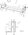
- Fig. 1 shows a perspective view of a container body 2 of a storage container without a decorative panel.
- the container body is made of transparent plastic and has a base 3, two end walls 4, 4 ′, and a half-height rear wall 8 and a half-height front wall 9.
- the end walls 4, 4 'each consist of three walls 5, 6, 7 or 5', 6 ', 7', which are aligned in the form of an inverted U-profile perpendicular to the front side or to the door of the refrigeration device. As a result, the three walls 5, 6, 7 enclose an opening 13 open to the front side between them.
- the opening 13 is open at the bottom, but the outer wall 7, 7 'has an inwardly projecting strip 12 at its lower edge. As in Fig. 5 shown, to prevent an inserted into the opening 13 downward projection from falling out.
- the end walls 4, 4 'of the storage container are shaped differently.
- the end walls 4, 4 'each have a recess 14, 14' which is suitable for hanging in a corresponding cam on the inner wall of the door of the refrigeration device.
- the container body can thus be mounted on the recesses 14, 14 'on the door of the refrigeration device.
- Both the rear wall 8 and the half-height front wall 9 facing the front side are optional and can in particular also be designed to be even less high.
- the function of the rear wall 8 can also be perceived through the inside of the door, while a decorative panel is placed on the front, which serves as a complete front wall.
- Fig. 2 shows a cross section through the right end wall 4 of the container body. This shows the inner wall 5, the upper wall 6 and the outer wall 7, which between them enclose an opening 13 open towards the front.
- the opening 13 is limited at the bottom on one side by the bar 12, which allows one from the front to hold the pushed-in projection of a decorative panel in the opening.
- a recess 15 is provided on the lower side of the upper wall 6 for secure mounting, which recess forms a latching connection together with a latching lug arranged on the projection of the decorative panel. In this way, the decorative panel can be held in a form-fitting manner on the container body.
- This type of attachment is based on the Figures 3-5 explained in more detail.
- Fig. 3 shows an example of a decorative panel 10. This can be made of wood, plastic or a plastic back part with a front made of wood or metal. In Fig. 3 you can see the front of the decorative panel or front wall.
- Fig. 4 shows the rear side, on which two projections 11, 11 'are formed. These can be formed, for example, by ribs arranged in a rectangular shape, which z. B. are formed from the plastic back of the decorative panel. Alternatively, the projections can also be milled out or produced by attaching wooden or plastic blocks to the base plate of the decorative panel.
- Fig. 5 shows a longitudinal section along the line VV in Fig. 4 through the decorative panel 10 when it is placed on a container body 2.
- parts of the decorative panel are hatched from bottom left to top right, parts of the container body 2 from top left to bottom right.
- the longitudinal section shows a section through the end wall 4 with the upper wall 6 and the opening 13 enclosed by the walls 5, 6, 7, into which the projection 11 of the decorative panel 10 is inserted. In the downward direction, the projection 11 is held in the opening 13 by the strip 12.
- a latching lug 16 is locked into the recess 15, where it is held by an undercut. In this way, the decorative panel 10 is held positively and firmly on the container body 2.
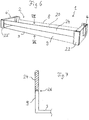
- Fig. 6 shows a storage container 1, consisting of a container body according to Fig. 1
- the decorative panel 20 has two side parts 22, 22 'which cover the front walls 4, 4' towards the front and are held in the openings 13 as described above by inserting projections 11, 11 '(not shown) into the openings 13 .
- the two side parts 22, 22 ′ are connected by a wall section 24 approximately in the upper area.
- the lower area between the sections 22, 22 ' is cut out, however, so that the transparent half-height front wall 9 becomes visible here.
- the decorative panel is preferably made of a non-transparent material, for example plastic, made so that an attractive image of the front of the storage container results, with the opaque wall sections 22, 22 'and 24, and underneath a transparent viewing window.
- this embodiment offers the advantage that the wall section 24 can be fastened to the top of the half-height front wall 9 by a tongue and groove connection, which in the cross section of FIG Figure 7 is recognizable.
- the bottom 3 of the container body can be seen, to which the half-height front wall 9 adjoins.
- the wall section 24 of the decorative panel is placed on this by the tongue and groove connection 26.
- the tongue and groove connection can also be omitted, and the decorative panel can only be held on the end walls 4, 4 '.
- Embodiments are also provided in which a gap is left between the wall section 24 and the half-height front wall 9.
- FIG. 4 shows a perspective view of a storage container 1, which in turn consists of the container body of FIG Figure 1 is assembled with yet another decorative panel 30.
- the decorative panel 30 is in turn inserted from the front into the openings 13 and is thereby held from the front on the end walls 4, 4 '.
- This decorative panel can consist of wood or plastic and is characterized by an elongated window 32. In the example shown, this is arranged in the area of the half-height front wall 9, so that preferably no objects can fall out through the window 32.
- Fig. 9 shows a plan view of yet another decorative panel, which has an outer frame 42 and a center piece 44 enclosed therein.
- the frame and middle piece are preferably made of different materials, for example the middle piece 44 made of wood and the frame 42 made of plastic. This can also form a plastic rear part with molded projections 11.
- the invention provides a storage container with a completely replaceable front.
- the concept described comprises a basic door rack component in the form of a constant container body, which can be equipped with different fronts or decorative panels.
- the fronts can differ both in their shape and in their materiality. This enables a high degree of differentiation to be achieved in a very simple manner.
Landscapes
- Engineering & Computer Science (AREA)
- Chemical & Material Sciences (AREA)
- Combustion & Propulsion (AREA)
- Physics & Mathematics (AREA)
- Mechanical Engineering (AREA)
- Thermal Sciences (AREA)
- General Engineering & Computer Science (AREA)
- Refrigerator Housings (AREA)
Claims (11)
- Balconnet (1) destiné au montage dans une porte d'un appareil frigorifique, notamment d'un appareil frigorifique à usage domestique, comportant un corps de stockage (2) comprenant un fond (3), deux parois frontales (4, 4'), optionnellement une paroi avant (9) disposée sur le côté frontal du balconnet (1), et un bandeau décoratif (10, 20, 30, 40) posé sur le côté frontal du balconnet (1), lequel bandeau décoratif forme une partie séparée du corps de stockage (2), dans lequel les parois frontales (4, 4') du corps de stockage (2) sont recouvertes au moins en partie par le bandeau décoratif (10, 20, 30, 40) en direction du côté frontal, dans lequel le bandeau décoratif (10, 20, 30, 40) est maintenu de manière fixe sur le corps de stockage (2), et caractérisé en ce que les parois frontales du corps de stockage (2) comprennent respectivement une ouverture (13) ouverte vers le côté frontal, dans laquelle une saillie correspondante (11) du bandeau décoratif (10, 20, 30, 40) est respectivement insérée.
- Balconnet (1) selon la revendication 1, caractérisé en ce que le bandeau décoratif (10, 20, 30, 40) s'étend sur toute la largeur et, au moins sur les côtés frontaux (4, 4') du balconnet (1), sur toute la hauteur du côté frontal du balconnet (1).
- Balconnet (1) selon la revendication 1 ou 2, caractérisé en ce que le bandeau décoratif (10, 20, 30, 40) est maintenu sur le corps de stockage par une liaison à adhérence de force et/ou à complémentarité de forme, notamment par une liaison d'insertion, dont la direction d'insertion est au moins essentiellement perpendiculaire au côté frontal.
- Balconnet (1) selon l'une quelconque des revendications précédentes, caractérisé en ce que le bandeau décoratif (10, 20, 30, 40) est maintenu sur le côté frontal du corps de stockage (2) dans la zone des parois frontales (4, 4').
- Balconnet (1) selon l'une quelconque des revendications précédentes, caractérisé en ce que le corps de stockage (2) ne comprend pas de paroi avant (9) ou comprend une paroi avant (9) de mi-hauteur.
- Balconnet (1) selon la revendication 5, caractérisé en ce que le bandeau décoratif (20) est fixé sur le côté supérieur de la paroi avant (9) de mi-hauteur par une liaison à rainure et languette (26).
- Balconnet (1) selon l'une quelconque des revendications précédentes, caractérisé en ce que le corps de stockage (2) est transparent au moins en partie.
- Balconnet (1) selon l'une quelconque des revendications précédentes, notamment selon la revendication 7, caractérisé en ce que le bandeau décoratif (20, 30), dans la zone entre les sections (22, 22') du bandeau décoratif (20, 30) recouvrant les parois frontales (4, 4'), comprend au moins un évidement qui s'étend optionnellement jusqu'au bord inférieur du bandeau décoratif (20, 30).
- Balconnet (1) selon l'une quelconque des revendications précédentes, caractérisé en ce que le bandeau décoratif (10, 20, 30, 40) est fabriqué en matière plastique, en matière plastique colorée, en matière plastique métallisée, en bois, en métal ou à partir d'un composite constitué d'une partie arrière en matière plastique et d'un côté supérieur en bois ou métal.
- Jeu constitué d'un balconnet (1) selon l'une quelconque des revendications précédentes et de bandeaux décoratifs supplémentaires (10, 20, 30, 40), dans lequel les bandeaux décoratifs (10, 20, 30, 40) présentent des couleurs et/ou des formes différentes et/ou sont fabriqués dans différentes matières, et peuvent être respectivement raccordés au même corps de stockage (2).
- Appareil frigorifique, notamment appareil frigorifique à usage domestique, comprenant un balconnet (1) selon l'une quelconque des revendications précédentes.
Applications Claiming Priority (2)
| Application Number | Priority Date | Filing Date | Title |
|---|---|---|---|
| DE102010003877A DE102010003877A1 (de) | 2010-04-12 | 2010-04-12 | Abstellbehälter mit Dekorblende |
| PCT/EP2011/054785 WO2011128203A1 (fr) | 2010-04-12 | 2011-03-29 | Balconnet à cadre décoratif |
Publications (2)
| Publication Number | Publication Date |
|---|---|
| EP2558801A1 EP2558801A1 (fr) | 2013-02-20 |
| EP2558801B1 true EP2558801B1 (fr) | 2020-09-16 |
Family
ID=44478799
Family Applications (1)
| Application Number | Title | Priority Date | Filing Date |
|---|---|---|---|
| EP11711539.4A Active EP2558801B1 (fr) | 2010-04-12 | 2011-03-29 | Balconnet à cadre décoratif |
Country Status (3)
| Country | Link |
|---|---|
| EP (1) | EP2558801B1 (fr) |
| DE (1) | DE102010003877A1 (fr) |
| WO (1) | WO2011128203A1 (fr) |
Family Cites Families (9)
| Publication number | Priority date | Publication date | Assignee | Title |
|---|---|---|---|---|
| DE8517955U1 (de) * | 1985-06-20 | 1985-08-08 | Bosch-Siemens Hausgeräte GmbH, 7000 Stuttgart | Kühlschranktür |
| DE4304483A1 (de) * | 1993-02-15 | 1994-08-18 | Bosch Siemens Hausgeraete | Scharnierverbindung zum beweglichen Verbinden von Bauteilen |
| DE10117763A1 (de) | 2001-04-09 | 2002-10-10 | Bsh Bosch Siemens Hausgeraete | Abstellbehälter für Kältegeräte |
| KR100432733B1 (ko) * | 2001-11-16 | 2004-05-24 | 주식회사 엘지이아이 | 냉장고의 도어바스켓 |
| DE10208063B4 (de) | 2002-02-25 | 2019-02-14 | BSH Hausgeräte GmbH | Türabsteller für ein Kältegerät |
| DE10208067B4 (de) | 2002-02-25 | 2016-11-10 | BSH Hausgeräte GmbH | Türabstellereinheit für ein Kältegerät |
| DE102005022516A1 (de) | 2005-05-11 | 2006-11-16 | BSH Bosch und Siemens Hausgeräte GmbH | Türabsteller für ein Kältegerät |
| DE202006013374U1 (de) * | 2006-06-16 | 2007-10-25 | Liebherr-Hausgeräte Ochsenhausen GmbH | Kühl- und/oder Gefriergeräte |
| DE102008026381A1 (de) | 2008-06-02 | 2009-12-03 | BSH Bosch und Siemens Hausgeräte GmbH | Türablagefach für ein Kältegerät |
-
2010
- 2010-04-12 DE DE102010003877A patent/DE102010003877A1/de not_active Withdrawn
-
2011
- 2011-03-29 EP EP11711539.4A patent/EP2558801B1/fr active Active
- 2011-03-29 WO PCT/EP2011/054785 patent/WO2011128203A1/fr not_active Ceased
Non-Patent Citations (1)
| Title |
|---|
| None * |
Also Published As
| Publication number | Publication date |
|---|---|
| DE102010003877A1 (de) | 2011-10-13 |
| EP2558801A1 (fr) | 2013-02-20 |
| WO2011128203A1 (fr) | 2011-10-20 |
Similar Documents
| Publication | Publication Date | Title |
|---|---|---|
| EP2549213B1 (fr) | Sol technique pour une armoire à provisions, ainsi qu'armoire à provisions destinée au stockage et à l'équilibrage thermique des bouteilles de boissons | |
| EP2464926B1 (fr) | Balconnet pour un appareil de froid | |
| DE102009046612A1 (de) | Kältegerät mit einem Türabsteller und einer schwimmend gelagerten Rastvorrichtung | |
| EP1379820B3 (fr) | Appareil frigorifique avec un récipient de stockage | |
| DE102009002325A1 (de) | Kältegerät mit gerahmter Tür | |
| DE202008005350U1 (de) | Abstellbehälter für ein Kältegerät | |
| DE102018107386A1 (de) | Aus vertikal und horizontal verlaufenden Profilteilen gebildetes Möbel sowie Möbel mit zumindest zwei Seitenwänden | |
| EP1980176A1 (fr) | Mobilier | |
| DE102006040358A1 (de) | Einbau-Kältegerät mit Ausgabevorrichtung | |
| DE102010003839A1 (de) | Türabsteller für ein Kältegerät | |
| DE202012100211U1 (de) | Einbauküche oder Küchenzeile | |
| EP2107325A1 (fr) | Châssis pour un appareil ménager | |
| DE10358734A1 (de) | Kältegerät mit einem mit Schiebetüren verschließbaren Behälter | |
| EP2558801A1 (fr) | Balconnet à cadre décoratif | |
| DE102012001374A1 (de) | Kühl- und/oder Gefriergerät | |
| DE202012003776U1 (de) | Auszug | |
| EP1926952B1 (fr) | Porte pour appareil frigorifique | |
| EP2023063A2 (fr) | Elément de fermeture de bord de porte d'une porte d'appareil ménager | |
| EP1379819A1 (fr) | Bac de rangement pour appareils frigorifiques | |
| WO2018158156A1 (fr) | Paroi d'un corps de meuble et corps de meuble ou meuble doté d'une telle paroi | |
| DE202005008202U1 (de) | Schiebetürenschrank | |
| DE2609619A1 (de) | Aus einzelbauteilen zusammengesetztes moebel | |
| DE7904621U1 (de) | Schrank | |
| DE20219692U1 (de) | Regal für Warenlagerung und Darbietung in Einzelhandelsgeschäften | |
| DE102012222641A1 (de) | Kältegerät mit Schwenkladenvorrichtung |
Legal Events
| Date | Code | Title | Description |
|---|---|---|---|
| PUAI | Public reference made under article 153(3) epc to a published international application that has entered the european phase |
Free format text: ORIGINAL CODE: 0009012 |
|
| 17P | Request for examination filed |
Effective date: 20121112 |
|
| AK | Designated contracting states |
Kind code of ref document: A1 Designated state(s): AL AT BE BG CH CY CZ DE DK EE ES FI FR GB GR HR HU IE IS IT LI LT LU LV MC MK MT NL NO PL PT RO RS SE SI SK SM TR |
|
| DAX | Request for extension of the european patent (deleted) | ||
| RAP1 | Party data changed (applicant data changed or rights of an application transferred) |
Owner name: BSH HAUSGERAETE GMBH |
|
| STAA | Information on the status of an ep patent application or granted ep patent |
Free format text: STATUS: EXAMINATION IS IN PROGRESS |
|
| 17Q | First examination report despatched |
Effective date: 20180821 |
|
| GRAP | Despatch of communication of intention to grant a patent |
Free format text: ORIGINAL CODE: EPIDOSNIGR1 |
|
| STAA | Information on the status of an ep patent application or granted ep patent |
Free format text: STATUS: GRANT OF PATENT IS INTENDED |
|
| INTG | Intention to grant announced |
Effective date: 20191217 |
|
| GRAJ | Information related to disapproval of communication of intention to grant by the applicant or resumption of examination proceedings by the epo deleted |
Free format text: ORIGINAL CODE: EPIDOSDIGR1 |
|
| STAA | Information on the status of an ep patent application or granted ep patent |
Free format text: STATUS: EXAMINATION IS IN PROGRESS |
|
| INTC | Intention to grant announced (deleted) | ||
| GRAP | Despatch of communication of intention to grant a patent |
Free format text: ORIGINAL CODE: EPIDOSNIGR1 |
|
| STAA | Information on the status of an ep patent application or granted ep patent |
Free format text: STATUS: GRANT OF PATENT IS INTENDED |
|
| INTG | Intention to grant announced |
Effective date: 20200504 |
|
| GRAS | Grant fee paid |
Free format text: ORIGINAL CODE: EPIDOSNIGR3 |
|
| GRAA | (expected) grant |
Free format text: ORIGINAL CODE: 0009210 |
|
| STAA | Information on the status of an ep patent application or granted ep patent |
Free format text: STATUS: THE PATENT HAS BEEN GRANTED |
|
| AK | Designated contracting states |
Kind code of ref document: B1 Designated state(s): AL AT BE BG CH CY CZ DE DK EE ES FI FR GB GR HR HU IE IS IT LI LT LU LV MC MK MT NL NO PL PT RO RS SE SI SK SM TR |
|
| REG | Reference to a national code |
Ref country code: GB Ref legal event code: FG4D Free format text: NOT ENGLISH |
|
| REG | Reference to a national code |
Ref country code: CH Ref legal event code: EP |
|
| REG | Reference to a national code |
Ref country code: DE Ref legal event code: R096 Ref document number: 502011016903 Country of ref document: DE |
|
| REG | Reference to a national code |
Ref country code: IE Ref legal event code: FG4D Free format text: LANGUAGE OF EP DOCUMENT: GERMAN |
|
| REG | Reference to a national code |
Ref country code: AT Ref legal event code: REF Ref document number: 1314525 Country of ref document: AT Kind code of ref document: T Effective date: 20201015 |
|
| PG25 | Lapsed in a contracting state [announced via postgrant information from national office to epo] |
Ref country code: FI Free format text: LAPSE BECAUSE OF FAILURE TO SUBMIT A TRANSLATION OF THE DESCRIPTION OR TO PAY THE FEE WITHIN THE PRESCRIBED TIME-LIMIT Effective date: 20200916 Ref country code: GR Free format text: LAPSE BECAUSE OF FAILURE TO SUBMIT A TRANSLATION OF THE DESCRIPTION OR TO PAY THE FEE WITHIN THE PRESCRIBED TIME-LIMIT Effective date: 20201217 Ref country code: NO Free format text: LAPSE BECAUSE OF FAILURE TO SUBMIT A TRANSLATION OF THE DESCRIPTION OR TO PAY THE FEE WITHIN THE PRESCRIBED TIME-LIMIT Effective date: 20201216 Ref country code: BG Free format text: LAPSE BECAUSE OF FAILURE TO SUBMIT A TRANSLATION OF THE DESCRIPTION OR TO PAY THE FEE WITHIN THE PRESCRIBED TIME-LIMIT Effective date: 20201216 Ref country code: SE Free format text: LAPSE BECAUSE OF FAILURE TO SUBMIT A TRANSLATION OF THE DESCRIPTION OR TO PAY THE FEE WITHIN THE PRESCRIBED TIME-LIMIT Effective date: 20200916 Ref country code: HR Free format text: LAPSE BECAUSE OF FAILURE TO SUBMIT A TRANSLATION OF THE DESCRIPTION OR TO PAY THE FEE WITHIN THE PRESCRIBED TIME-LIMIT Effective date: 20200916 |
|
| REG | Reference to a national code |
Ref country code: NL Ref legal event code: MP Effective date: 20200916 |
|
| PG25 | Lapsed in a contracting state [announced via postgrant information from national office to epo] |
Ref country code: LV Free format text: LAPSE BECAUSE OF FAILURE TO SUBMIT A TRANSLATION OF THE DESCRIPTION OR TO PAY THE FEE WITHIN THE PRESCRIBED TIME-LIMIT Effective date: 20200916 Ref country code: RS Free format text: LAPSE BECAUSE OF FAILURE TO SUBMIT A TRANSLATION OF THE DESCRIPTION OR TO PAY THE FEE WITHIN THE PRESCRIBED TIME-LIMIT Effective date: 20200916 |
|
| REG | Reference to a national code |
Ref country code: LT Ref legal event code: MG4D |
|
| PG25 | Lapsed in a contracting state [announced via postgrant information from national office to epo] |
Ref country code: CZ Free format text: LAPSE BECAUSE OF FAILURE TO SUBMIT A TRANSLATION OF THE DESCRIPTION OR TO PAY THE FEE WITHIN THE PRESCRIBED TIME-LIMIT Effective date: 20200916 Ref country code: EE Free format text: LAPSE BECAUSE OF FAILURE TO SUBMIT A TRANSLATION OF THE DESCRIPTION OR TO PAY THE FEE WITHIN THE PRESCRIBED TIME-LIMIT Effective date: 20200916 Ref country code: LT Free format text: LAPSE BECAUSE OF FAILURE TO SUBMIT A TRANSLATION OF THE DESCRIPTION OR TO PAY THE FEE WITHIN THE PRESCRIBED TIME-LIMIT Effective date: 20200916 Ref country code: NL Free format text: LAPSE BECAUSE OF FAILURE TO SUBMIT A TRANSLATION OF THE DESCRIPTION OR TO PAY THE FEE WITHIN THE PRESCRIBED TIME-LIMIT Effective date: 20200916 Ref country code: PT Free format text: LAPSE BECAUSE OF FAILURE TO SUBMIT A TRANSLATION OF THE DESCRIPTION OR TO PAY THE FEE WITHIN THE PRESCRIBED TIME-LIMIT Effective date: 20210118 Ref country code: RO Free format text: LAPSE BECAUSE OF FAILURE TO SUBMIT A TRANSLATION OF THE DESCRIPTION OR TO PAY THE FEE WITHIN THE PRESCRIBED TIME-LIMIT Effective date: 20200916 Ref country code: SM Free format text: LAPSE BECAUSE OF FAILURE TO SUBMIT A TRANSLATION OF THE DESCRIPTION OR TO PAY THE FEE WITHIN THE PRESCRIBED TIME-LIMIT Effective date: 20200916 |
|
| PG25 | Lapsed in a contracting state [announced via postgrant information from national office to epo] |
Ref country code: AL Free format text: LAPSE BECAUSE OF FAILURE TO SUBMIT A TRANSLATION OF THE DESCRIPTION OR TO PAY THE FEE WITHIN THE PRESCRIBED TIME-LIMIT Effective date: 20200916 Ref country code: IS Free format text: LAPSE BECAUSE OF FAILURE TO SUBMIT A TRANSLATION OF THE DESCRIPTION OR TO PAY THE FEE WITHIN THE PRESCRIBED TIME-LIMIT Effective date: 20210116 Ref country code: ES Free format text: LAPSE BECAUSE OF FAILURE TO SUBMIT A TRANSLATION OF THE DESCRIPTION OR TO PAY THE FEE WITHIN THE PRESCRIBED TIME-LIMIT Effective date: 20200916 Ref country code: PL Free format text: LAPSE BECAUSE OF FAILURE TO SUBMIT A TRANSLATION OF THE DESCRIPTION OR TO PAY THE FEE WITHIN THE PRESCRIBED TIME-LIMIT Effective date: 20200916 |
|
| REG | Reference to a national code |
Ref country code: DE Ref legal event code: R097 Ref document number: 502011016903 Country of ref document: DE |
|
| PG25 | Lapsed in a contracting state [announced via postgrant information from national office to epo] |
Ref country code: SK Free format text: LAPSE BECAUSE OF FAILURE TO SUBMIT A TRANSLATION OF THE DESCRIPTION OR TO PAY THE FEE WITHIN THE PRESCRIBED TIME-LIMIT Effective date: 20200916 |
|
| PLBE | No opposition filed within time limit |
Free format text: ORIGINAL CODE: 0009261 |
|
| STAA | Information on the status of an ep patent application or granted ep patent |
Free format text: STATUS: NO OPPOSITION FILED WITHIN TIME LIMIT |
|
| 26N | No opposition filed |
Effective date: 20210617 |
|
| PG25 | Lapsed in a contracting state [announced via postgrant information from national office to epo] |
Ref country code: SI Free format text: LAPSE BECAUSE OF FAILURE TO SUBMIT A TRANSLATION OF THE DESCRIPTION OR TO PAY THE FEE WITHIN THE PRESCRIBED TIME-LIMIT Effective date: 20200916 Ref country code: DK Free format text: LAPSE BECAUSE OF FAILURE TO SUBMIT A TRANSLATION OF THE DESCRIPTION OR TO PAY THE FEE WITHIN THE PRESCRIBED TIME-LIMIT Effective date: 20200916 |
|
| PG25 | Lapsed in a contracting state [announced via postgrant information from national office to epo] |
Ref country code: MC Free format text: LAPSE BECAUSE OF FAILURE TO SUBMIT A TRANSLATION OF THE DESCRIPTION OR TO PAY THE FEE WITHIN THE PRESCRIBED TIME-LIMIT Effective date: 20200916 Ref country code: IT Free format text: LAPSE BECAUSE OF FAILURE TO SUBMIT A TRANSLATION OF THE DESCRIPTION OR TO PAY THE FEE WITHIN THE PRESCRIBED TIME-LIMIT Effective date: 20200916 |
|
| REG | Reference to a national code |
Ref country code: CH Ref legal event code: PL |
|
| GBPC | Gb: european patent ceased through non-payment of renewal fee |
Effective date: 20210329 |
|
| REG | Reference to a national code |
Ref country code: BE Ref legal event code: MM Effective date: 20210331 |
|
| PG25 | Lapsed in a contracting state [announced via postgrant information from national office to epo] |
Ref country code: LI Free format text: LAPSE BECAUSE OF NON-PAYMENT OF DUE FEES Effective date: 20210331 Ref country code: LU Free format text: LAPSE BECAUSE OF NON-PAYMENT OF DUE FEES Effective date: 20210329 Ref country code: CH Free format text: LAPSE BECAUSE OF NON-PAYMENT OF DUE FEES Effective date: 20210331 Ref country code: FR Free format text: LAPSE BECAUSE OF NON-PAYMENT OF DUE FEES Effective date: 20210331 Ref country code: IE Free format text: LAPSE BECAUSE OF NON-PAYMENT OF DUE FEES Effective date: 20210329 Ref country code: GB Free format text: LAPSE BECAUSE OF NON-PAYMENT OF DUE FEES Effective date: 20210329 |
|
| REG | Reference to a national code |
Ref country code: AT Ref legal event code: MM01 Ref document number: 1314525 Country of ref document: AT Kind code of ref document: T Effective date: 20210329 |
|
| PG25 | Lapsed in a contracting state [announced via postgrant information from national office to epo] |
Ref country code: BE Free format text: LAPSE BECAUSE OF NON-PAYMENT OF DUE FEES Effective date: 20210331 |
|
| PG25 | Lapsed in a contracting state [announced via postgrant information from national office to epo] |
Ref country code: AT Free format text: LAPSE BECAUSE OF NON-PAYMENT OF DUE FEES Effective date: 20210329 |
|
| REG | Reference to a national code |
Ref country code: DE Ref legal event code: R084 Ref document number: 502011016903 Country of ref document: DE |
|
| PG25 | Lapsed in a contracting state [announced via postgrant information from national office to epo] |
Ref country code: HU Free format text: LAPSE BECAUSE OF FAILURE TO SUBMIT A TRANSLATION OF THE DESCRIPTION OR TO PAY THE FEE WITHIN THE PRESCRIBED TIME-LIMIT; INVALID AB INITIO Effective date: 20110329 Ref country code: CY Free format text: LAPSE BECAUSE OF FAILURE TO SUBMIT A TRANSLATION OF THE DESCRIPTION OR TO PAY THE FEE WITHIN THE PRESCRIBED TIME-LIMIT Effective date: 20200916 |
|
| PG25 | Lapsed in a contracting state [announced via postgrant information from national office to epo] |
Ref country code: MK Free format text: LAPSE BECAUSE OF FAILURE TO SUBMIT A TRANSLATION OF THE DESCRIPTION OR TO PAY THE FEE WITHIN THE PRESCRIBED TIME-LIMIT Effective date: 20200916 |
|
| PG25 | Lapsed in a contracting state [announced via postgrant information from national office to epo] |
Ref country code: MT Free format text: LAPSE BECAUSE OF FAILURE TO SUBMIT A TRANSLATION OF THE DESCRIPTION OR TO PAY THE FEE WITHIN THE PRESCRIBED TIME-LIMIT Effective date: 20200916 |
|
| PGFP | Annual fee paid to national office [announced via postgrant information from national office to epo] |
Ref country code: DE Payment date: 20260331 Year of fee payment: 16 |
|
| PGFP | Annual fee paid to national office [announced via postgrant information from national office to epo] |
Ref country code: TR Payment date: 20260327 Year of fee payment: 16 |
|
| PGFP | Annual fee paid to national office [announced via postgrant information from national office to epo] |
Ref country code: PL Payment date: 20260325 Year of fee payment: 16 |