EP2559328B1 - Cache pour dispositif de climatisation - Google Patents
Cache pour dispositif de climatisation Download PDFInfo
- Publication number
- EP2559328B1 EP2559328B1 EP11708282.6A EP11708282A EP2559328B1 EP 2559328 B1 EP2559328 B1 EP 2559328B1 EP 11708282 A EP11708282 A EP 11708282A EP 2559328 B1 EP2559328 B1 EP 2559328B1
- Authority
- EP
- European Patent Office
- Prior art keywords
- cover
- cladding element
- cover housing
- hook
- towards
- Prior art date
- Legal status (The legal status is an assumption and is not a legal conclusion. Google has not performed a legal analysis and makes no representation as to the accuracy of the status listed.)
- Active
Links
Images


Classifications
-
- H—ELECTRICITY
- H05—ELECTRIC TECHNIQUES NOT OTHERWISE PROVIDED FOR
- H05K—PRINTED CIRCUITS; CASINGS OR CONSTRUCTIONAL DETAILS OF ELECTRIC APPARATUS; MANUFACTURE OF ASSEMBLAGES OF ELECTRICAL COMPONENTS
- H05K7/00—Constructional details common to different types of electric apparatus
- H05K7/20—Modifications to facilitate cooling, ventilating, or heating
- H05K7/20009—Modifications to facilitate cooling, ventilating, or heating using a gaseous coolant in electronic enclosures
- H05K7/20136—Forced ventilation, e.g. by fans
- H05K7/20181—Filters; Louvers
-
- F—MECHANICAL ENGINEERING; LIGHTING; HEATING; WEAPONS; BLASTING
- F24—HEATING; RANGES; VENTILATING
- F24F—AIR-CONDITIONING; AIR-HUMIDIFICATION; VENTILATION; USE OF AIR CURRENTS FOR SCREENING
- F24F1/00—Room units for air-conditioning, e.g. separate or self-contained units or units receiving primary air from a central station
- F24F1/06—Separate outdoor units, e.g. outdoor unit to be linked to a separate room comprising a compressor and a heat exchanger
- F24F1/56—Casing or covers of separate outdoor units, e.g. fan guards
- F24F1/58—Separate protective covers for outdoor units, e.g. solar guards, snow shields or camouflage
-
- F—MECHANICAL ENGINEERING; LIGHTING; HEATING; WEAPONS; BLASTING
- F24—HEATING; RANGES; VENTILATING
- F24F—AIR-CONDITIONING; AIR-HUMIDIFICATION; VENTILATION; USE OF AIR CURRENTS FOR SCREENING
- F24F13/00—Details common to, or for air-conditioning, air-humidification, ventilation or use of air currents for screening
- F24F13/20—Casings or covers
Definitions
- the invention relates to a cover for at least one arranged on a cladding element, in particular a control cabinet air conditioning device, with a cover housing having a front wall and attached side parts, wherein the side panels spaced from the front wall to hold the cladding element and the cladding element at least one holder for the cover housing is attached, and wherein the holder has vertical hook elements, in which the cover housing can be hooked with hook receivers in the direction of gravity.
- Cabinets are often operated in environments exposed to dust and moisture.
- the cabinets are sealed from the environment.
- the heat generated by the electronic internals can not be dissipated sufficiently by convection alone.
- a breakthrough is cut out of a cladding element, for example a side wall or a cover part, which covers the control cabinet.
- an air conditioning device is used. About this air can be sucked in from the environment for cooling or delivered to this.
- Fans, intake ducts or the like are often used as air conditioning units. Often, even the breakthrough as air conditioning device is sufficient for increased convection.
- the opening is covered with a filter mat.
- cover To keep out moisture, such as rain or spray, is for example from the DE 43 44 659 C1 known to use a cover.
- the cover consists of a closed, only down to the vertical side wall of the cabinet open towards cover housing.
- fixing screws are used. These are made by mounting shots of the fan inserted in the breakthrough of the side wall.
- On the voltage applied to the side wall rear wall of the cover housing bores are provided, protrude through the bolts of the mounting screws. Nuts are screwed onto the bolts so that the fan and the cover housing are braced with the side wall.
- This assembly is very expensive, since first of the inside of the cabinet, the mounting screws and the fan must be kept by one person. A second person now leads through the downwardly open cover housing from the outside of the cabinet forth the nuts to the bolts and counter these.
- a cover opposite the cover according to DE 43 44 659 C1 is easier to assemble, is out of the DE 196 41 553 C2 known.
- the holder according to DE 196 41 553 C2 has guides on which the cover can be attached.
- the cover is connected directly to the stable cladding element. This measure ensures that even with a force acting on the cover, the underlying units can not be easily damaged.
- the holder is further equipped with the vertically extending guides on which the cover with guide shots is pushed bar. The guides are held spaced from the cladding element.
- the cover housing can be fastened to the cladding element.
- the cover housing must be attached with its guide shots on the guides.
- a considerable space above the guides is necessary, which is determined by the length of the cover housing.
- the disassembly of the known cover is correspondingly expensive.
- the EP 0 979 978 A2 discloses a portable air conditioning system whose housing is closed by a cover in which hook elements are provided, which engage in corresponding openings of the front part of the housing portion.
- the JP 10-009610 A deals with an air conditioning unit, whose housing is suspended by hooks attached to a wall.
- the JP 5-296487 A shows a housing of an air conditioner, which is hung by means of a cross-section over an upstanding edge of a bracket.
- the JP 58-102034 shows an air conditioner, which is to be installed in a window. For this purpose it is hung on hooks, which are provided on an installation frame.
- a cover of the type mentioned is from the EP 1 031 799 A2 known.
- the cover described therein has hook elements in the region of its side edges, which are aligned with hook receptacles which are mounted in side parts of a housing and hooked into this, wherein a foam tape seal is compressed, which is to protect the housing interior from contamination.
- the cover is intended to protect the covered air conditioning effectively against splashing water and especially against strong, directed water jets, so form a so-called jet water hood.
- the holder for the cover housing is mounted directly on the cladding element.
- the hook receptacles provided on your cover housing are formed in receiving profiles which are connected to the associated side parts and extend along these side parts of the cover housing.
- the receiving profiles in each case have at least one profile section arranged transversely to the protruding direction of the hook elements and carrying the hook receivers.
- the mounting profiles ensure stable storage of the cover housing.
- they In order to create a particularly stable mounting option for the recording profiles, they each have a contact region which adjoins the profile section carrying the hook receptacles and is folded parallel to the associated side part of the cover housing.
- the contact area is connected to the inside of the associated side part, in particular glued or welded or soldered.
- the profile section carrying the hook receivers is bent at its free end at an angle in the direction of the cladding element to form a threading aid for the hook elements.
- the cover housing In order to disengage the hook receptacles of the cover housing with the hook elements, the cover housing must be raised only by the vertical hook length. The same small footprint upwards is needed for mounting or hooking the hook receivers in the hook elements.
- a cladding element such as a side wall, a door or a cover part of a cabinet, is easy to handle and the space required overall low.
- the cover housing can also have vertical hook elements which can be hung in hook receptacles of the holder in the direction of gravity.
- the holder may comprise at least two mutually spaced, projecting from the cladding element in the direction of the cover housing leg.
- Each leg has at least one vertical, projecting from the legs in the direction of the cover housing hook element.
- the holder may comprise a U-shaped support with two legs, which are interconnected by a connecting portion.
- a trained holder is particularly stable and particularly easy to handle by its one-piece design during assembly.
- the connecting portion defines the distance between the two legs.
- an opening may be formed in the connecting portion between the two legs, which is substantially aligned with the opening in the cladding element and in which the air conditioning device can be arranged.
- the connection section can surround the air-conditioning device like a frame.
- the legs may be formed as flat molded parts, wherein the hook elements are integrally formed with the legs as an extension thereof.
- Such flat moldings can be easily made of metal or plastic.
- the one-piece design of legs and hook elements is particularly stable.
- the hook receptacles may be formed as vertical receiving slots, in which the vertical, narrow hook elements can be hung in the direction of gravity.
- the receiving profiles may have an adjacent to the contact area, L-shaped bent profile section which forms an open towards the cladding element, extending along the side parts of the cover housing vertical seal receptacle.
- the vertical seal receptacle can be inserted in the direction of the cladding element at least partially protruding sealing element.
- the cover housing is hung with the hook receptacles in the hook elements, the protruding part of the sealing member comes into contact with the cladding element.
- the sealing element is compressed so that it creates a sealing abutment.
- the sealing element serves as a spring element against whose spring force the hook receptacles must be hooked into the hook elements.
- a standing at an angle thereto cover part can be connected at the front wall of the cover housing.
- This sloping cover part forms a bent in the direction of the cladding element horizontal support portion.
- a protruding from the inside of the cover member in the direction of the cladding element, spaced from the support portion web defines a horizontal sealing receptacle open in the direction of the cladding element.
- a sealing element protruding at least partially in the direction of the cladding element can be inserted into the horizontal seal receiver.
- a particularly good sealing can be achieved by arranging on the side parts and the support section of the cover housing a circumferential seal receptacle for receiving a sealing element which protrudes at least partially in the direction of the lining element.
- a sealing element which protrudes at least partially in the direction of the lining element.
- the cover housing can be manufactured as a stamped and bent part made of metal, for example V2A steel or a plastic.
- FIG. 1 shows a schematic and sectional side view of a cover for a arranged on the outside of a cladding element 10 of a control cabinet air conditioning device 50.
- the cladding element 10 is a side wall of a control cabinet.
- FIG. 2 shows in a schematic sectional view along the section line II-II in FIG. 1 the cover according to the FIG. 1 ,
- the air conditioning device 50 is shown substantially in the figures as a greatly simplified "black box”.
- the illustrated air conditioning device 50 is designed as a fan with a fan assembly that transports cool ambient air into the cabinet interior.
- the air conditioning device may also be designed as a fan with a fan assembly, which transports heated air from the cabinet interior to the outside.
- the air conditioning device can also be realized without a fan assembly.
- the air conditioning device 50 shown in the figures is inserted in an opening 60 in the cladding element 10.
- the air conditioning device 50 has a fan housing 52, which has the fan assembly, not shown. From outside a filter mat 54 is applied to the fan housing 52. On the outside, the filter mat 54 is held by an attached lamellar grid 56.
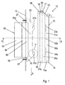
- the cover has a cover housing 12 with a front wall 13. As based on the FIG. 2 becomes clear, a left side part 14a and a right side part 14b is connected to the front wall 13. The side parts 14a and 14b keep the front wall 13 spaced from the cladding element 10.
- the cover housing 12 is made as a stamped and bent part made of V2A sheet steel. On the cladding element 10, a holder 20 for the cover housing 12 is attached.
- the holder 20 is formed as a U-shaped carrier and has two spaced apart, from the cladding element 10 in the direction of the cover housing 12 projecting, vertically extending legs, the left leg 25a and the right leg 25b, on.
- the left leg 25a has two vertical hook elements 21a and 22a arranged one above the other.
- the right thigh has a lower and an upper hook element, of which in the FIG. 2 only the upper hook element 21 b is shown.
- the legs 25a and 25b are formed as flat stamped parts made of sheet steel.
- the hook elements 21 a, 21 b and 22 a are integrally formed with the legs 25 a and 25 b as an extension thereof.
- the two legs 25 a and 25 b of the U-shaped carrier are connected to each other by a connecting portion 26.
- the legs 25 a and 25 b are formed integrally with the connecting portion 26.
- an opening 70 is likewise formed, which is aligned with the opening 60 in the lining element 10.
- the air conditioning device 50 is used.
- the connecting portion 26 surrounds the air-conditioning device 50 in the shape of a frame on the outside of the trim element 10. In the frame region of the connecting portion 26 holes for the implementation of fastening screws 27 are mounted, which in turn are inserted in the trim element 10 mounted screw receptacles.
- the cover housing 12 with hook receivers 33 a, 33 b and 34 a, which are formed as vertical receiving slots, hang in the direction of gravity according to the arrow S.
- the hook receivers 33a, 33b and 34a are formed in profile sections 31a and 31b of receiving profiles 30a and 30b extending along the side portions 14a and 14b of the cover housing 12.
- the profile sections 31 a and 31 b are transversely to the direction of protrusion of the hook elements 21 a, 21 b; 22a arranged.
- the left profile section 31 a has two superimposed vertical hook receptacles 33 a and 34 a.
- the right profile section 31 b has a lower and an upper hook receptacle, of which in the FIG. 2 only the upper hook receptacle 33b is shown.
- the receiving profiles 30a and 30b have contact areas 36a and 36b which abut on the hook receivers 33a, 33b and 34a carrying profile sections 31a and 31b and are bent parallel to the associated side parts 14a and 14b of the cover housing 12.
- the left and right receiving profiles 30a and 30b are welded with their abutting portions 36a and 36b to the associated left and right side portions 14a and 14b, respectively.
- the hook receptacles 33a and 33b carrying profile sections 31 a and 31 b are bent at its free end in each case at an angle in the direction of the lining element 10.
- the folds each form a threading aid 32a and 32b for the hook elements.
- the receiving profiles 30a and 30b each have a profile section 37a and 37b adjoining the contact region 36a or 36b and projecting in an L-shaped manner.
- the left profile section 37a forms an open in the direction of the cladding element 10, along the left side portion 14a of the cover housing 12 extending vertical left seal receptacle 38a.
- the right-hand profile section 37b likewise forms a vertical right-hand seal receptacle 38a, which is open in the direction of the lining element 10 and extends along the right-hand side part 14b of the cover housing 12.
- a partially projecting in the direction of the cladding element 10 sealing element 39 is inserted.
- a circumferential seal receptacle is formed, in which the sealing element 39 is inserted as an elongated, one-piece, elastic molded part.
- FIG. 3 shows in a schematic and sectional side view of the cover according to the FIGS. 1 and 2 wherein the cover housing 12 is engaged with the holder 20.
- FIG. 4 shows in a schematic sectional view along the section line IV-IV in FIG. 3 the cover according to the FIG. 3 ,
- the protruding part of the sealing member 39 comes into contact with the cladding element 10.
- the sealing element 39 is compressed so that it creates a sealing engagement with the cladding element 10.
- the sealing element 39 is due to its elastic deformability as a spring element against the spring force the hook receptacles 33a and 34a must be hooked into the hook elements.
- the hook receivers 33a and 34a of the cover housing 12 must be disengaged from the hook members 21a and 22a of the holder 20. In this case, caused by the spring force of the sealing element 39 pressing force must be overcome. For this purpose, for example, with the palm of your hand to the lower edge region of the cover housing 12 directed against the direction of gravity S force applied. The lower edge region of the cover housing 12 is folded inwards on the front wall 13 and forms an edge protector 19 for the palm of the hand.
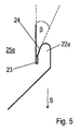
- FIG. 5 shows in an enlarged view in the FIG. 1 in the dashed circle V shown portion of the hook member 22a.
- the hook element 22a has a vertical, upwardly open receiving gap 23 for the hook receptacle 33a.
- the hook element 22a extends from the tip of the hook to the receiving gap 23 in a bevel inclined at angle ⁇ 24.
- the hook receptacle 33a passes during assembly in the region of the ramp 24, it is at a movement in the direction of gravity S on the ramp along sliding in the direction of Recording gap 23 crowded.
- the cover housing 12 is also urged in the direction of the cladding element 10, so that the protruding part of the sealing element 39 comes into sealing contact with the cladding element 10.
Landscapes
- Engineering & Computer Science (AREA)
- Microelectronics & Electronic Packaging (AREA)
- Chemical & Material Sciences (AREA)
- Combustion & Propulsion (AREA)
- Mechanical Engineering (AREA)
- General Engineering & Computer Science (AREA)
- Physics & Mathematics (AREA)
- Thermal Sciences (AREA)
- Casings For Electric Apparatus (AREA)
Claims (7)
- Cache pour au moins un dispositif de climatisation (50) monté sur un élément de parement (10) d'une armoire de commande, ledit cache comportant un carter (12), muni d'une paroi avant (13) et d'éléments latéraux (14a ; 14b) attachés à celle-ci, les éléments latéraux (14a ; 14b) maintenant la paroi avant (13) à une distance de l'élément de parement (10), et au moins une fixation (20) pour le carter (12) étant attachée à l'élément de parement (10), et ladite fixation (20) comportant des crochets (21a, 21b ; 22a) dans lesquels le carter (12) peut être accroché via des logements pour crochets (33a, 33b ; 34a) dans le sens de la pesanteur (S),
caractérisé
en ce que les logements pour crochets (33a, 33b ; 34a), prévus sur le carter (12), sont réalisés dans des profilés de fixation (30a, 30b), qui sont attachés aux éléments latéraux (14a ; 14b) et s'étendent le long des éléments latéraux (14a ; 14b) du carter (12) et qui comportent chacun au moins une partie de profilé (31a, 31b) disposée transversalement au sens de proéminence des crochets (21a, 21b ; 22a) et portant les logements pour crochets (33a ; 33b ; 34a),
en ce que la partie de profilé (31a, 31b) portant les logements pour crochets (33a ; 33b ; 34a) est pliée au niveau de son extrémité libre en un angle dirigé vers l'élément de parement (10) pour former une aide à l'enfichage (32a, 32b) pour les crochets (21a, 21b ; 22a), et
les profilés de fixation (30a, 30b) comportent chacun une zone d'appui (36a, 36b), qui est adjacente à la partie de profilé (31a, 31b) portant les logements pour crochets (33a ; 33b ; 34a) et est parallèle à l'élément latéral (14a ; 14b) correspondant du carter (12) et qui est attachée à la face intérieure de l'élément latéral (14a ; 14b) correspondant. - Cache selon la revendication 1, caractérisé en ce que la fixation (20) comporte au moins deux branches (25a, 25b) écartées l'une de l'autre et en saillie sur l'élément de parement (10) vers le carter (12), chaque branche (25a, 25b) comportant au moins un crochet (21a, 21b ; 22a) vertical, en saillie sur les branches (25a, 25b) vers le carter (12).
- Cache selon la revendication 2, caractérisé en ce que dans l'élément de parement (10), entre les deux branches (25a, 25b), est réalisée une percée (60), dans laquelle peut être agencé le dispositif de climatisation (50).
- Cache selon la revendication 2 ou 3, caractérisé en ce que la fixation (20) comporte un support en forme de U avec deux branches (25a, 25b) qui sont reliées l'une à l'autre par une partie de liaison (26).
- Cache selon la revendication 4, caractérisé en ce que dans la partie de liaison (26), entre les deux branches (25a, 25b), est réalisée une percée (70), qui est sensiblement alignée à la percée (60) dans l'élément de parement (10) et dans laquelle peut être agencé le dispositif de climatisation (50).
- Cache selon la revendication 1, caractérisé en ce que les profilés de fixation (30a, 30b) comportent une partie de profilé (37a, 37b) qui est pliée en L et est adjacente à la zone d'appui (36a, 36b) et qui forme un logement d'étanchéité (38a, 38b) vertical, qui est ouvert vers l'élément de parement (10) et s'étend le long des éléments latéraux (14a ; 14b) du carter (12) et dans lequel peut être inséré un élément d'étanchéité (39) au moins partiellement en saillie vers l'élément de parement (10).
- Cache selon l'une quelconque des revendications 1 à 6, caractérisé en ce qu'à la paroi avant (13) du carter (12) est attaché un couvercle (15) qui forme un angle (α) avec celle-ci et qui forme une partie d'appui (16) horizontale pliée vers l'élément de parement (10), une ailette (17), située à distance de la partie d'appui (16) et en saillie sur la face intérieure du couvercle (15) vers l'élément de parement (10), étant prévue et définissant un logement d'étanchéité (18) horizontal ouvert vers l'élément de parement (10), dans lequel peut être inséré un élément d'étanchéité (39) au moins partiellement en saillie vers l'élément de parement (10).
Applications Claiming Priority (2)
| Application Number | Priority Date | Filing Date | Title |
|---|---|---|---|
| DE102010016488A DE102010016488B4 (de) | 2010-04-16 | 2010-04-16 | Abdeckung für eine Klimatisierungseinrichtung |
| PCT/EP2011/053896 WO2011128168A1 (fr) | 2010-04-16 | 2011-03-15 | Cache pour dispositif de climatisation |
Publications (2)
| Publication Number | Publication Date |
|---|---|
| EP2559328A1 EP2559328A1 (fr) | 2013-02-20 |
| EP2559328B1 true EP2559328B1 (fr) | 2013-12-25 |
Family
ID=44591651
Family Applications (1)
| Application Number | Title | Priority Date | Filing Date |
|---|---|---|---|
| EP11708282.6A Active EP2559328B1 (fr) | 2010-04-16 | 2011-03-15 | Cache pour dispositif de climatisation |
Country Status (4)
| Country | Link |
|---|---|
| US (1) | US8827778B2 (fr) |
| EP (1) | EP2559328B1 (fr) |
| DE (1) | DE102010016488B4 (fr) |
| WO (1) | WO2011128168A1 (fr) |
Cited By (1)
| Publication number | Priority date | Publication date | Assignee | Title |
|---|---|---|---|---|
| WO2025248566A1 (fr) | 2024-05-27 | 2025-12-04 | Fandis S.P.A. | Couvercle pour dispositifs de filtration et de ventilation montés sur des éléments de placage d'une armoire électrique |
Families Citing this family (9)
| Publication number | Priority date | Publication date | Assignee | Title |
|---|---|---|---|---|
| JP6384670B2 (ja) * | 2015-01-13 | 2018-09-05 | 富士電機株式会社 | 空冷式電気機器、及び、空冷式電気機器におけるエアフィルタの着脱方法 |
| CN107921840B (zh) * | 2015-08-27 | 2021-04-02 | 株式会社电装 | 外壳单元 |
| US10690357B1 (en) * | 2017-03-16 | 2020-06-23 | Hail Protection, Inc | Air-cooled condenser hail protection system |
| DE102017105923B4 (de) | 2017-03-20 | 2018-10-11 | Stego-Holding Gmbh | Vorrichtung mit (Strahlwasser-)Haube |
| CN106989500A (zh) * | 2017-05-04 | 2017-07-28 | 苏州昆拓热控系统股份有限公司 | 一种机柜空调器 |
| US11286840B2 (en) | 2018-01-19 | 2022-03-29 | Hoffman Enclosures, Inc. | Fan shroud |
| US12048114B2 (en) | 2021-04-12 | 2024-07-23 | Hoffman Enclosures Inc. | Air conditioner for sealed enclosures |
| US20230081004A1 (en) * | 2021-09-14 | 2023-03-16 | Hoffman Enclosures Inc. | Cover for an Air Conditioner for Sealed Enclosures |
| CN116518468A (zh) * | 2023-04-28 | 2023-08-01 | 中建八局装饰工程有限公司 | 空调外机装饰罩加装装置及加装方法 |
Family Cites Families (13)
| Publication number | Priority date | Publication date | Assignee | Title |
|---|---|---|---|---|
| US2869501A (en) * | 1953-02-12 | 1959-01-20 | Stransky Gustave | Water-tight hatch cover |
| US4222318A (en) * | 1978-12-11 | 1980-09-16 | Patton Electric Co., Inc. | Combination window and floor fan |
| JPS58102034A (ja) | 1981-12-11 | 1983-06-17 | Matsushita Electric Ind Co Ltd | 空気調和機の取付装置 |
| US4803307A (en) * | 1987-06-29 | 1989-02-07 | Shotey Michael J | Weatherproof outlet cover |
| DE9108281U1 (de) * | 1991-07-04 | 1991-09-05 | Siemens AG, 8000 München | Luftführungssystem für einen Schaltschrank mit Fremdbelüftung |
| JP3076664B2 (ja) | 1992-04-21 | 2000-08-14 | 松下冷機株式会社 | 空気調和機の据付装置 |
| DE4344659C1 (de) | 1993-12-24 | 1995-05-04 | Haewa Programmgehaeuse & Kompo | Filterlüfter zum Anbau an spritzwassergeschützte Gehäuse oder Schaltschränke |
| DE19520084C1 (de) * | 1995-06-01 | 1996-07-25 | Loh Kg Rittal Werk | Schaltschrank mit Rahmengestell und Wandelementen |
| JP3070661B2 (ja) | 1996-06-26 | 2000-07-31 | 船井電機株式会社 | 空気調和機の室内機 |
| DE19641553C2 (de) | 1996-10-09 | 1999-12-09 | Loh Kg Rittal Werk | Abdeckung für eine Klimatisierungseinrichtung |
| ES2160447B1 (es) | 1998-08-13 | 2002-05-16 | Bsh Fabricacion Sa | Acondicionador de aire movil. |
| US6345511B1 (en) | 1999-02-25 | 2002-02-12 | Kooltronic, Incorporated | Air handling apparatus |
| US20050007747A1 (en) * | 2003-07-11 | 2005-01-13 | Michael Axelrod | Metal electronics device enclosure |
-
2010
- 2010-04-16 DE DE102010016488A patent/DE102010016488B4/de active Active
-
2011
- 2011-03-15 US US13/261,471 patent/US8827778B2/en active Active
- 2011-03-15 WO PCT/EP2011/053896 patent/WO2011128168A1/fr not_active Ceased
- 2011-03-15 EP EP11708282.6A patent/EP2559328B1/fr active Active
Cited By (1)
| Publication number | Priority date | Publication date | Assignee | Title |
|---|---|---|---|---|
| WO2025248566A1 (fr) | 2024-05-27 | 2025-12-04 | Fandis S.P.A. | Couvercle pour dispositifs de filtration et de ventilation montés sur des éléments de placage d'une armoire électrique |
Also Published As
| Publication number | Publication date |
|---|---|
| EP2559328A1 (fr) | 2013-02-20 |
| US20130040554A1 (en) | 2013-02-14 |
| DE102010016488A1 (de) | 2011-10-20 |
| WO2011128168A1 (fr) | 2011-10-20 |
| US8827778B2 (en) | 2014-09-09 |
| DE102010016488B4 (de) | 2013-09-05 |
Similar Documents
| Publication | Publication Date | Title |
|---|---|---|
| EP2559328B1 (fr) | Cache pour dispositif de climatisation | |
| EP1867376B1 (fr) | Ventilateur a filtre comprenant un dispositif de fixation rapide | |
| EP1939456B1 (fr) | Dispositif de passage d'air | |
| EP1262095B1 (fr) | Dispositif d'aeration | |
| EP1437038B1 (fr) | Ensemble d'etancheite | |
| EP2487429A9 (fr) | Boîtier carré, notamment en forme de cube, pour la réception de composants d'une installation technique de climatisation et/ou d'air ambiant | |
| DE102010016489B4 (de) | Gehäuseteil für einen Schaltschrank | |
| DE102013214897B4 (de) | Spritzschutz für Fahrzeug | |
| DE102008011672B4 (de) | Kabelführungsvorrichtung | |
| DE102009000867A1 (de) | Profilsystem für einen Aufsatz-Rollladenkasten | |
| DE202013000910U1 (de) | Rahmensystem für eine Insekten- und/oder Pollenschutztür | |
| DE19641553C2 (de) | Abdeckung für eine Klimatisierungseinrichtung | |
| EP4097803A1 (fr) | Boîtier rapporté | |
| DE4414905C2 (de) | Befestigungseinrichtung für ein Verkleidungsteil an einer Karosserieteilwandung | |
| DE19708063C1 (de) | Filterlüfter | |
| DE102008052730B4 (de) | Kleingehäuse | |
| DE102023204835A1 (de) | Dichtungsprofil und Anordnung des Dichtungsprofils zwischen einer Brüstung und einer Fensterscheibe im dichtungsfreien Design | |
| DE102006059034B3 (de) | Verfahren zum Anbringen eines Bauteils an einer Wand eines Kraftfahrzeugs sowie entsprechendes Bauteil und Kraftfahrzeug | |
| DE102010003038B4 (de) | Verbesserter Filterkasten | |
| DE102008056909A1 (de) | Befestigungssystem für ein Hakenelement an einem Strukturteil | |
| DE102009045343A1 (de) | Kältegerät mit Ventilatorbaugruppe | |
| DE102017105923A1 (de) | Vorrichtung mit (Strahlwasser-)Haube | |
| DE20208609U1 (de) | Luftdurchtrittseinrichtung | |
| DE29609709U1 (de) | Gehäuse | |
| EP1463167A2 (fr) | Armoire |
Legal Events
| Date | Code | Title | Description |
|---|---|---|---|
| PUAI | Public reference made under article 153(3) epc to a published international application that has entered the european phase |
Free format text: ORIGINAL CODE: 0009012 |
|
| 17P | Request for examination filed |
Effective date: 20120817 |
|
| AK | Designated contracting states |
Kind code of ref document: A1 Designated state(s): AL AT BE BG CH CY CZ DE DK EE ES FI FR GB GR HR HU IE IS IT LI LT LU LV MC MK MT NL NO PL PT RO RS SE SI SK SM TR |
|
| DAX | Request for extension of the european patent (deleted) | ||
| REG | Reference to a national code |
Ref country code: DE Ref legal event code: R079 Ref document number: 502011001887 Country of ref document: DE Free format text: PREVIOUS MAIN CLASS: H05K0007200000 Ipc: F24F0001580000 |
|
| GRAP | Despatch of communication of intention to grant a patent |
Free format text: ORIGINAL CODE: EPIDOSNIGR1 |
|
| RIC1 | Information provided on ipc code assigned before grant |
Ipc: F24F 13/20 20060101ALI20130917BHEP Ipc: H05K 7/20 20060101ALI20130917BHEP Ipc: F24F 1/58 20110101AFI20130917BHEP |
|
| INTG | Intention to grant announced |
Effective date: 20131007 |
|
| GRAS | Grant fee paid |
Free format text: ORIGINAL CODE: EPIDOSNIGR3 |
|
| GRAA | (expected) grant |
Free format text: ORIGINAL CODE: 0009210 |
|
| AK | Designated contracting states |
Kind code of ref document: B1 Designated state(s): AL AT BE BG CH CY CZ DE DK EE ES FI FR GB GR HR HU IE IS IT LI LT LU LV MC MK MT NL NO PL PT RO RS SE SI SK SM TR |
|
| REG | Reference to a national code |
Ref country code: GB Ref legal event code: FG4D Free format text: NOT ENGLISH |
|
| REG | Reference to a national code |
Ref country code: CH Ref legal event code: EP |
|
| REG | Reference to a national code |
Ref country code: AT Ref legal event code: REF Ref document number: 646836 Country of ref document: AT Kind code of ref document: T Effective date: 20140115 |
|
| REG | Reference to a national code |
Ref country code: IE Ref legal event code: FG4D Free format text: LANGUAGE OF EP DOCUMENT: GERMAN |
|
| REG | Reference to a national code |
Ref country code: DE Ref legal event code: R096 Ref document number: 502011001887 Country of ref document: DE Effective date: 20140213 |
|
| PG25 | Lapsed in a contracting state [announced via postgrant information from national office to epo] |
Ref country code: FI Free format text: LAPSE BECAUSE OF FAILURE TO SUBMIT A TRANSLATION OF THE DESCRIPTION OR TO PAY THE FEE WITHIN THE PRESCRIBED TIME-LIMIT Effective date: 20131225 Ref country code: HR Free format text: LAPSE BECAUSE OF FAILURE TO SUBMIT A TRANSLATION OF THE DESCRIPTION OR TO PAY THE FEE WITHIN THE PRESCRIBED TIME-LIMIT Effective date: 20131225 Ref country code: LT Free format text: LAPSE BECAUSE OF FAILURE TO SUBMIT A TRANSLATION OF THE DESCRIPTION OR TO PAY THE FEE WITHIN THE PRESCRIBED TIME-LIMIT Effective date: 20131225 Ref country code: NO Free format text: LAPSE BECAUSE OF FAILURE TO SUBMIT A TRANSLATION OF THE DESCRIPTION OR TO PAY THE FEE WITHIN THE PRESCRIBED TIME-LIMIT Effective date: 20140325 Ref country code: SE Free format text: LAPSE BECAUSE OF FAILURE TO SUBMIT A TRANSLATION OF THE DESCRIPTION OR TO PAY THE FEE WITHIN THE PRESCRIBED TIME-LIMIT Effective date: 20131225 |
|
| REG | Reference to a national code |
Ref country code: NL Ref legal event code: VDEP Effective date: 20131225 |
|
| REG | Reference to a national code |
Ref country code: LT Ref legal event code: MG4D |
|
| PG25 | Lapsed in a contracting state [announced via postgrant information from national office to epo] |
Ref country code: LV Free format text: LAPSE BECAUSE OF FAILURE TO SUBMIT A TRANSLATION OF THE DESCRIPTION OR TO PAY THE FEE WITHIN THE PRESCRIBED TIME-LIMIT Effective date: 20131225 Ref country code: RS Free format text: LAPSE BECAUSE OF FAILURE TO SUBMIT A TRANSLATION OF THE DESCRIPTION OR TO PAY THE FEE WITHIN THE PRESCRIBED TIME-LIMIT Effective date: 20131225 |
|
| PG25 | Lapsed in a contracting state [announced via postgrant information from national office to epo] |
Ref country code: IS Free format text: LAPSE BECAUSE OF FAILURE TO SUBMIT A TRANSLATION OF THE DESCRIPTION OR TO PAY THE FEE WITHIN THE PRESCRIBED TIME-LIMIT Effective date: 20140425 Ref country code: EE Free format text: LAPSE BECAUSE OF FAILURE TO SUBMIT A TRANSLATION OF THE DESCRIPTION OR TO PAY THE FEE WITHIN THE PRESCRIBED TIME-LIMIT Effective date: 20131225 |
|
| PG25 | Lapsed in a contracting state [announced via postgrant information from national office to epo] |
Ref country code: SK Free format text: LAPSE BECAUSE OF FAILURE TO SUBMIT A TRANSLATION OF THE DESCRIPTION OR TO PAY THE FEE WITHIN THE PRESCRIBED TIME-LIMIT Effective date: 20131225 Ref country code: CZ Free format text: LAPSE BECAUSE OF FAILURE TO SUBMIT A TRANSLATION OF THE DESCRIPTION OR TO PAY THE FEE WITHIN THE PRESCRIBED TIME-LIMIT Effective date: 20131225 Ref country code: ES Free format text: LAPSE BECAUSE OF FAILURE TO SUBMIT A TRANSLATION OF THE DESCRIPTION OR TO PAY THE FEE WITHIN THE PRESCRIBED TIME-LIMIT Effective date: 20131225 Ref country code: RO Free format text: LAPSE BECAUSE OF FAILURE TO SUBMIT A TRANSLATION OF THE DESCRIPTION OR TO PAY THE FEE WITHIN THE PRESCRIBED TIME-LIMIT Effective date: 20131225 Ref country code: CY Free format text: LAPSE BECAUSE OF FAILURE TO SUBMIT A TRANSLATION OF THE DESCRIPTION OR TO PAY THE FEE WITHIN THE PRESCRIBED TIME-LIMIT Effective date: 20131225 Ref country code: PT Free format text: LAPSE BECAUSE OF FAILURE TO SUBMIT A TRANSLATION OF THE DESCRIPTION OR TO PAY THE FEE WITHIN THE PRESCRIBED TIME-LIMIT Effective date: 20140428 Ref country code: NL Free format text: LAPSE BECAUSE OF FAILURE TO SUBMIT A TRANSLATION OF THE DESCRIPTION OR TO PAY THE FEE WITHIN THE PRESCRIBED TIME-LIMIT Effective date: 20131225 |
|
| REG | Reference to a national code |
Ref country code: DE Ref legal event code: R097 Ref document number: 502011001887 Country of ref document: DE |
|
| PG25 | Lapsed in a contracting state [announced via postgrant information from national office to epo] |
Ref country code: LU Free format text: LAPSE BECAUSE OF FAILURE TO SUBMIT A TRANSLATION OF THE DESCRIPTION OR TO PAY THE FEE WITHIN THE PRESCRIBED TIME-LIMIT Effective date: 20140315 Ref country code: DK Free format text: LAPSE BECAUSE OF FAILURE TO SUBMIT A TRANSLATION OF THE DESCRIPTION OR TO PAY THE FEE WITHIN THE PRESCRIBED TIME-LIMIT Effective date: 20131225 |
|
| PLBE | No opposition filed within time limit |
Free format text: ORIGINAL CODE: 0009261 |
|
| REG | Reference to a national code |
Ref country code: CH Ref legal event code: PL |
|
| STAA | Information on the status of an ep patent application or granted ep patent |
Free format text: STATUS: NO OPPOSITION FILED WITHIN TIME LIMIT |
|
| PG25 | Lapsed in a contracting state [announced via postgrant information from national office to epo] |
Ref country code: PL Free format text: LAPSE BECAUSE OF FAILURE TO SUBMIT A TRANSLATION OF THE DESCRIPTION OR TO PAY THE FEE WITHIN THE PRESCRIBED TIME-LIMIT Effective date: 20131225 |
|
| 26N | No opposition filed |
Effective date: 20140926 |
|
| REG | Reference to a national code |
Ref country code: IE Ref legal event code: MM4A |
|
| REG | Reference to a national code |
Ref country code: DE Ref legal event code: R097 Ref document number: 502011001887 Country of ref document: DE Effective date: 20140926 |
|
| PG25 | Lapsed in a contracting state [announced via postgrant information from national office to epo] |
Ref country code: LI Free format text: LAPSE BECAUSE OF NON-PAYMENT OF DUE FEES Effective date: 20140331 Ref country code: CH Free format text: LAPSE BECAUSE OF NON-PAYMENT OF DUE FEES Effective date: 20140331 Ref country code: IE Free format text: LAPSE BECAUSE OF NON-PAYMENT OF DUE FEES Effective date: 20140315 |
|
| PG25 | Lapsed in a contracting state [announced via postgrant information from national office to epo] |
Ref country code: SI Free format text: LAPSE BECAUSE OF FAILURE TO SUBMIT A TRANSLATION OF THE DESCRIPTION OR TO PAY THE FEE WITHIN THE PRESCRIBED TIME-LIMIT Effective date: 20131225 |
|
| PG25 | Lapsed in a contracting state [announced via postgrant information from national office to epo] |
Ref country code: MT Free format text: LAPSE BECAUSE OF FAILURE TO SUBMIT A TRANSLATION OF THE DESCRIPTION OR TO PAY THE FEE WITHIN THE PRESCRIBED TIME-LIMIT Effective date: 20131225 |
|
| REG | Reference to a national code |
Ref country code: FR Ref legal event code: PLFP Year of fee payment: 6 |
|
| PG25 | Lapsed in a contracting state [announced via postgrant information from national office to epo] |
Ref country code: SM Free format text: LAPSE BECAUSE OF FAILURE TO SUBMIT A TRANSLATION OF THE DESCRIPTION OR TO PAY THE FEE WITHIN THE PRESCRIBED TIME-LIMIT Effective date: 20131225 |
|
| PG25 | Lapsed in a contracting state [announced via postgrant information from national office to epo] |
Ref country code: MC Free format text: LAPSE BECAUSE OF FAILURE TO SUBMIT A TRANSLATION OF THE DESCRIPTION OR TO PAY THE FEE WITHIN THE PRESCRIBED TIME-LIMIT Effective date: 20131225 |
|
| PG25 | Lapsed in a contracting state [announced via postgrant information from national office to epo] |
Ref country code: GR Free format text: LAPSE BECAUSE OF FAILURE TO SUBMIT A TRANSLATION OF THE DESCRIPTION OR TO PAY THE FEE WITHIN THE PRESCRIBED TIME-LIMIT Effective date: 20140326 Ref country code: BG Free format text: LAPSE BECAUSE OF FAILURE TO SUBMIT A TRANSLATION OF THE DESCRIPTION OR TO PAY THE FEE WITHIN THE PRESCRIBED TIME-LIMIT Effective date: 20131225 |
|
| PG25 | Lapsed in a contracting state [announced via postgrant information from national office to epo] |
Ref country code: BE Free format text: LAPSE BECAUSE OF FAILURE TO SUBMIT A TRANSLATION OF THE DESCRIPTION OR TO PAY THE FEE WITHIN THE PRESCRIBED TIME-LIMIT Effective date: 20140331 Ref country code: HU Free format text: LAPSE BECAUSE OF FAILURE TO SUBMIT A TRANSLATION OF THE DESCRIPTION OR TO PAY THE FEE WITHIN THE PRESCRIBED TIME-LIMIT; INVALID AB INITIO Effective date: 20110315 Ref country code: TR Free format text: LAPSE BECAUSE OF FAILURE TO SUBMIT A TRANSLATION OF THE DESCRIPTION OR TO PAY THE FEE WITHIN THE PRESCRIBED TIME-LIMIT Effective date: 20131225 |
|
| REG | Reference to a national code |
Ref country code: FR Ref legal event code: PLFP Year of fee payment: 7 |
|
| REG | Reference to a national code |
Ref country code: AT Ref legal event code: MM01 Ref document number: 646836 Country of ref document: AT Kind code of ref document: T Effective date: 20160315 |
|
| PG25 | Lapsed in a contracting state [announced via postgrant information from national office to epo] |
Ref country code: AT Free format text: LAPSE BECAUSE OF NON-PAYMENT OF DUE FEES Effective date: 20160315 |
|
| REG | Reference to a national code |
Ref country code: FR Ref legal event code: PLFP Year of fee payment: 8 |
|
| PG25 | Lapsed in a contracting state [announced via postgrant information from national office to epo] |
Ref country code: MK Free format text: LAPSE BECAUSE OF FAILURE TO SUBMIT A TRANSLATION OF THE DESCRIPTION OR TO PAY THE FEE WITHIN THE PRESCRIBED TIME-LIMIT Effective date: 20131225 |
|
| PG25 | Lapsed in a contracting state [announced via postgrant information from national office to epo] |
Ref country code: AL Free format text: LAPSE BECAUSE OF FAILURE TO SUBMIT A TRANSLATION OF THE DESCRIPTION OR TO PAY THE FEE WITHIN THE PRESCRIBED TIME-LIMIT Effective date: 20131225 |
|
| P01 | Opt-out of the competence of the unified patent court (upc) registered |
Effective date: 20230525 |
|
| PGFP | Annual fee paid to national office [announced via postgrant information from national office to epo] |
Ref country code: FR Payment date: 20250324 Year of fee payment: 15 |
|
| PGFP | Annual fee paid to national office [announced via postgrant information from national office to epo] |
Ref country code: GB Payment date: 20250324 Year of fee payment: 15 |
|
| PGFP | Annual fee paid to national office [announced via postgrant information from national office to epo] |
Ref country code: IT Payment date: 20250331 Year of fee payment: 15 |
|
| PGFP | Annual fee paid to national office [announced via postgrant information from national office to epo] |
Ref country code: DE Payment date: 20260320 Year of fee payment: 16 |