EP2559355A1 - Dispositif destiné à déplacer une pièce de meuble mobile, unité de guidage et meuble - Google Patents
Dispositif destiné à déplacer une pièce de meuble mobile, unité de guidage et meuble Download PDFInfo
- Publication number
- EP2559355A1 EP2559355A1 EP12005924A EP12005924A EP2559355A1 EP 2559355 A1 EP2559355 A1 EP 2559355A1 EP 12005924 A EP12005924 A EP 12005924A EP 12005924 A EP12005924 A EP 12005924A EP 2559355 A1 EP2559355 A1 EP 2559355A1
- Authority
- EP
- European Patent Office
- Prior art keywords
- furniture
- opening
- unit
- guide
- opening device
- Prior art date
- Legal status (The legal status is an assumption and is not a legal conclusion. Google has not performed a legal analysis and makes no representation as to the accuracy of the status listed.)
- Granted
Links
Images


Classifications
-
- A—HUMAN NECESSITIES
- A47—FURNITURE; DOMESTIC ARTICLES OR APPLIANCES; COFFEE MILLS; SPICE MILLS; SUCTION CLEANERS IN GENERAL
- A47B—TABLES; DESKS; OFFICE FURNITURE; CABINETS; DRAWERS; GENERAL DETAILS OF FURNITURE
- A47B88/00—Drawers for tables, cabinets or like furniture; Guides for drawers
- A47B88/40—Sliding drawers; Slides or guides therefor
- A47B88/453—Actuated drawers
- A47B88/46—Actuated drawers operated by mechanically-stored energy, e.g. by springs
- A47B88/47—Actuated drawers operated by mechanically-stored energy, e.g. by springs having both self-opening and self-closing mechanisms which interact with each other
Definitions
- the invention relates to a device for moving a movable furniture part according to the preamble of claim 1 and a guide unit and a piece of furniture with such a device.
- devices for moving movable furniture parts e.g. Doors, drawers or work surfaces in a variety of designs known. They serve to support movements when opening or closing movable furniture parts at least along part of a possible range of movement. In addition, they can e.g. specify a closed position.
- devices for moving movable furniture parts in a guide unit. In particular, if mechanical means are provided to support a plurality of different movements in parallel, but partially mutually opposite directions, their integration can lead to comparatively complex solutions or significantly increase the space required for a guide unit.
- the present invention solves the problem of providing a device for moving a movable furniture part, which can be comparatively simple and space-saving in a piece of furniture, especially in a guide unit, accommodate.
- the object is achieved by a device for moving a movable furniture part with the features of claim 1 and by a guide unit according to claim 12 and a piece of furniture Claim 15 solved.
- the invention relates to a device for moving a movable furniture part relative to a furniture body comprising an opening device, a collection device and a driver, which cooperates with the collection device includes.
- the opening device and the retraction device provide forces for opening and retracting movements of the movable furniture part.
- the essence of the invention is that the opening device and the collection device are provided for connection to a first furniture element in such a way that the collection device is slidably mounted on the first furniture element to the opening device, wherein the driver is provided for attachment to a second furniture element, the moves relative to the first furniture element in opening and retracting movements of the furniture part, and that the collection device is coupled to the opening device.
- the movable furniture part may e.g. a drawer or e.g. be an extendable worktop.
- the movable furniture part may be movable to, for example, a furniture body on which it may be fitted with e.g. a guide unit is movably mounted.
- Under a furniture element here is any portion of a piece of furniture, e.g. also a furniture part, understood.
- the collection device is slidably mounted to the opening device, these two devices can be moved closer together, for example, in a closed state of the movable furniture part in a piece of furniture.
- the device according to the invention may require less space at least temporarily.
- a sliding relative to the opening device attachment of the collection device and a coupling of these two Devices it is possible to cooperate with the driver, for example via the collection device with the opening device.
- a specially provided for the opening device additional driver is advantageously dispensable.
- the driver is therefore preferably provided for cooperation with both the retraction device and with the opening device.
- the device according to the invention may advantageously be composed of an opening device and a collection device, which may be e.g. individually also in different products, e.g. different embodiments of the invention, can be used. As a result, an economically advantageous production of the device according to the invention is favored.
- the opening device may include an ejection unit and an ejection member movably supported in the ejection unit.
- the ejection unit preferably comprises a separate drive element, for example a force accumulator, in particular a spring.
- the drive element is preferably provided for ejecting the ejection element.
- a switching device can be accommodated in the ejection unit, with which, for example, a closed state of the movable furniture part can be predetermined.
- a collection device may comprise a collection unit and a collection element, which is movably mounted in the collection unit.
- the feed unit also includes its own drive element, which may be a force storage device, in particular a spring.
- the drive element of the intake unit is preferably provided for retracting the intake element.
- a further switching device can be accommodated in the feeder unit, which can temporarily lock, for example, the feeder element until a renewed engagement of the driver in an extended position.
- a preferred embodiment of the invention provides that, for coupling the opening device with the retraction device, an ejection element of the opening device, which is movably mounted in an ejection unit of the opening device, is constantly connected directly or indirectly to the retraction device.
- an ejection movement of the opening device, in particular of the ejection element can advantageously be used for extending the feed device and, in particular, the intake element.
- the ejection element is connected to a feed unit of the feed device, in which a feed element is movably mounted.
- the feeder unit can thereby be displaced, for example, with the discharge element in the direction of the discharge unit, while the feeder element, e.g. is temporarily fixed in an extended position.
- the collection device and the opening device are arranged one behind the other.
- a comparatively narrow construction is possible, which can be relatively easier to accommodate in a piece of furniture or a part of the furniture.
- the opening device and the intake device can be arranged one behind the other in such a way that an ejection element and a retraction element move along a geometric straight line passing through both elements. This results in comparatively little friction correspondingly less wear on the opening and the intake device. This is further promoted by the opening device is designed for a straight-line ejection movement of an ejection element.
- a further preferred embodiment of the invention is that a mounting body is provided for attachment to the first furniture element, on which the opening device is firmly positioned and the collection device is slidably mounted.
- the effort for attaching the device according to the invention can be reduced.
- a slidable attachment of the collection device a slidable in particular on the mounting body slide be provided.
- a possibly already available collection device can be mounted comparatively easily on the carriage in order to achieve a displaceable attachment to the first furniture element.
- a first guide slot on the first furniture element is provided for slidably attaching the catchment device to the first furniture element.
- movements of the retraction device can be advantageously reduced to movements, e.g. of the ejection element.
- the first guide slot is formed on the mounting body, so that machining on the first furniture element for the formation of a guide slot are reduced or dispensed with.
- a housing of the feeder unit or e.g. the carriage be tuned to the first guide slot.
- a particularly preferred embodiment of the invention provides that a second guide slot on the first furniture element is provided to guide the catchment element, in particular a catch element formed thereon, during movements of the collection device or else of the driver.
- the second guide slot can in particular be designed to lock the catchment element in an extended position until, for example, the catch engages with the catchment element in the course of a retracting movement of the movable furniture part.
- the collection device in particular its intake unit, be slidably mounted between the opening device and, for example, a detent position for the intake element on the second guide slot.
- the feeder device in particular the feeder unit
- the ejection element is pushed into the ejection unit and the feeder element can be pulled out of the feeder unit, so that eg Power storage both the opening device and the collection device are simultaneously loadable.
- the second guide slot can advantageously be formed on the mounting body, in particular together with the first guide slot. This facilitates the adaptation of the second guide slot to the other components of the device, in particular to the opening device, the collection device and optionally the first guide link.
- a preferred embodiment of the invention is that the device comprises an actuating device which is adapted to push the retraction device in the course of an extending movement of the movable furniture part to the ejection unit, when the ejection element is in an ejected position.
- the actuator comprises a transmission, e.g. a Switzerlandstoff-, a gear or a lever mechanism or a combination of different types of transmissions.
- a transmission e.g. a Switzerlandstoff-, a gear or a lever mechanism or a combination of different types of transmissions. This can be advantageous to keep low when removing the movable furniture part of the user's effort.
- the adjusting device preferably comprises a repulsion unit, which is provided for attachment to the first furniture element and which can cooperate with a driving unit, which is provided for fixed attachment to a third furniture element which moves during opening and retracting movements of the furniture part relative to the first furniture element.
- the retraction unit for pushing back the retraction device in particular the retraction unit, is provided, wherein the entrainment unit is intended to drive the retracting unit in a predetermined section of opening movements of the movable furniture part.
- the opening and the retraction device on Furniture carcass, the driver on the movable furniture part and the driving unit to be mounted on a guide rail, wherein the guide rail can move during opening and retraction movements, for example, both the furniture body and the movable furniture part.
- the third furniture element may optionally coincide with the second.
- the entrainment unit is mounted on the third furniture element such that cooperation with the retracting unit can only take place when the driver is not in engagement with the retraction unit.
- the driver and the entrainment unit may be arranged at a predetermined distance, wherein the distance is chosen sufficiently large that different movement processes of the embodiment according to the invention during time opening or closing movement of the movable furniture part can never overlap.
- the driving unit has a driving element which is mounted so movably on the driving unit, that the driving element cooperates only in one of two opposite directions of movement of the third furniture element with the push-back unit.
- the entrainment element can be displaced by a pivotable detent element, which in one direction of movement entrains an actuating element of the retraction unit, while it can be displaced in the opposite direction due to a ramped abutment surface by the actuating element.
- a direction sensitive design of the retract unit e.g. a transmission can be dispensed with, which makes it comparatively simpler and more compact build.
- the adjusting device has a control device, the interaction of the driving unit with the retracting unit only at a Opening movement of the furniture part allows, in which the device changes from a stable closed state directly into an ejecting opening movement.
- a range of movement of the movable furniture part in the open state can be predetermined, in which the furniture part can be moved in and out as often as desired without operating the opening device or the collection device.
- a guide unit for a movable furniture part is equiped with a device according to the invention, in particular with one or more of the aforementioned design features.
- This offers the advantage that in a piece of furniture for the opening and the draw-in unit no separate area of space is required next to that for the guide unit.
- a guide rail of the guide unit may be the first furniture element.
- the guide unit according to the invention is designed so that the opening device is fixed to a guide rail of the guide unit and the collection device is slidably mounted to the opening device.
- the guide rail advantageously serves as a mounting body for the opening and the retraction devices.
- the first or the second guide slot or both can also be provided on a guide rail designed as a mounting body and, if appropriate, the adjusting device, in particular the reset unit, can also be attached thereto.
- the driver which cooperates with the intake unit at least temporarily, may be formed on a guide rail of the guide unit, which is in the opening and closing movements of the furniture part relative to the first furniture part emotional.
- the driving unit of the adjusting device may be formed on a guide rail of the guide unit, which moves relative to the first furniture part during opening and closing movements of the furniture part.
- FIGS. 1 to 5 show an embodiment of a ceremoniesseinneit invention 1 according to the invention with a carcass rail 10 and a pull-out rail 30.
- the pull-out rail 30 may be directly or indirectly, for example via a middle rail (not shown), mounted on a guide portion 12 of the carcass rail 10.
- the body rail 10 is as a mounting body for an opening device 50 and a Feeding device 60 is formed, which can for example be attached to a side wall (not shown) of a furniture body (not shown). Between an attachment section 11 and the guide section 12 of the carcass rail 10, an opening device 50 and a collection device 60 are arranged one behind the other in the longitudinal direction of the carcass rail 10.
- a housing 51 of the opening device 50 is attached to the carcass rail 10. From the housing 51 protrudes a plunger 52 which is slidably mounted and guided as an ejection element in the housing 51.
- the opening device 50 includes a force accumulator (not shown) and a switching mechanism (not shown), with which several different states of the opening device 50, e.g. can be reached by switching movements. Both the energy storage and the switching mechanism of the opening device 50 may be housed in the housing 51, so that the housing 51 corresponds to an ejection unit.
- the switching mechanism of the opening device 50 may e.g. a switching element with a heart curve (not shown).
- at least one state of the opening device 50 is provided for applying ejecting forces to the plunger 52 for extending the pull-out rail 30 on the guide unit 1.
- the plunger 52 does not transmit ejecting forces directly to the pull-out rail 30 but is temporarily connected to it via the collection device 60.
- the opening device 50 provides at least a second state, in which the plunger 52 and thus also the pull-out rail 30 is retained in a predetermined closed position.
- the collection device 60 has a housing 61 which is mounted on a carriage 62 and is mounted with this jointly displaceable on the carcass rail 10.
- An outstanding end of the plunger 52 may be fixedly connected to the carriage 62 to couple movements of the plunger 52 to displacements of the carriage 62 and the housing 61 in the longitudinal direction of the guide unit 1 to each other.
- a recess 13 (s. Figure 3 ) formed in the sliding portions 63 of the carriage 62 engage.
- the recess 13 and the sliding portions 63 thus form a first guide slot for guiding displacement movements of the retraction device 60 and provide a comparatively low-friction guidance of displacements of the carriage 62 with the housing 61, this preferably on common parallel movements of the collection device 60 and the plunger 52 of Opening device 50 are tuned.
- the length of the recess 13 may, for example, coincide with at least the maximum path length over which the plunger 52 is ejected. As a result, a comparatively large part of the pulse, which can be stored, for example, in the opening device, is transmitted to the carriage 62 and thus to the intake device 60.
- the housing 61 of the collection device 60 From the housing 61 of the collection device 60 projects a rod 65 (s. Fig.1 ) out, which is movably mounted in the housing 61.
- the housing 61 of the collection device 60 also contains a force accumulator (not shown).
- the energy accumulator is preferably rechargeable by pulling out the rod 65.
- the retraction device 60 can thus be prepared to provide forces for subsequent retraction of the drawer rail 30 by means of the rod 65.
- the housing 61 assumes the function of a collection unit of the collection device 60th
- An end of the rod 65 protruding from the housing 61 is e.g. firmly connected to a coupling element 67.
- a catch element 69 is e.g. with a hinge 68 pivotally mounted on the coupling joint 67. Together, the rod 65, the coupling element 67, the joint 68 and the catch element 69 form a collection element of the collection device 60.
- the catching element 69 has a cam 70, which engages in a second guide slot 14 on the carcass rail 10.
- the guide slot 14 can from the carcass rail 10, for example by Punching or be cut out eg by laser cutting.
- the guide slot 14 is largely designed as an elongated slot 14a.
- the slot 14a extends straight and parallel to the longitudinal axis of the carcass rail 10 and thereby also parallel to possible displacement movements of the carriage 62 and the plunger 52.
- end of the guide slot 14 latter is bent to the side of the attachment portion 11 out and forms a latching portion 14b.
- the elongated slot 14 a and the latching portion 14 b together have at least a length corresponding to the displacement path of the feed unit, in particular the length of the ejection movement of the plunger 52.
- the guide slot is preferably matched to the opening device 50 in such a way that the cam 70 moves in the latching section when the plunger passes through a section of an ejection movement that is extended comparatively far, for example outermost.
- the locking portion 14b is provided to release the catch element 69 from engagement of a driver 31 of the pull-out rail 30 and to hold the cam 70 in this section, as long as the driver 31 is outside the effective range of the guide slot 14.
- the catch element 69 is connected via the joint 68 with the coupling element 67 in a pivotally movable connection.
- the joint 68 in the region of the straight slot 14a, the catch element 69 can be brought into engagement with the catch 31 of the pull-out rail 30 and be released from engagement of the catch 31 in the region of the catch section 14b.
- the driver 31 and the catch element 69 are engaged with each other, extending and retracting forces can be transmitted from the catch element 69 to the pull-out rail.
- a lever 16 is pivotally mounted on a rotary bearing 17 on an underside of the carcass rail 10.
- two arms 18, 19 of the actuating lever 16 extend in opposite directions.
- An engagement arm 18 extends to the recess 13th and engages between two stops 64 on an underside of the carriage 62 which extend through the recess 13. With the help of the stops 64, it is possible to move the carriage 62 in the recess 13 parallel to the longitudinal axis of the carcass rail 10 with the engagement arm 18.
- actuating arm 19 Opposite to the engagement arm 18 extends from the pivot bearing 17 an actuating arm 19 which projects from the space profile of the carcass rail 10.
- the actuating arm 19 protrudes freely into an environment of the carcass rail 10 and can from a mounted guide unit 1, for. extending horizontally into an interior of a furniture body (not shown).
- the actuating arm 19 is preferably designed to be longer than the engagement arm 18 in order to achieve a lever ratio with which the actuating lever 16 can be moved in a controlled manner with lower forces than act on the engagement arm 18. This offers the advantage that the actuating lever 16 when entrained during an extension movement, e.g. a drawer-loaded lever ratio corresponding to reduced forces on the furniture part (not shown) transmits and for a. complete removal of the furniture part only comparatively small e.g. Tensile forces are applied by a user.
- a fixed extension arm 32 is formed, which is separated from the pull-out rail 30 e.g. protrudes vertically and horizontally in an interior of a furniture body (not shown) may protrude.
- the extension arm 32 is provided as a driving unit of the guide unit 1 and forms together with the adjusting lever 16 and the pivot bearing 17 an adjusting device of the embodiment according to the invention.
- the pivot bearings 37 for both flaps 33, 34 are arranged parallel to one another and along a common axis of rotation, wherein the axis of rotation extends horizontally and perpendicular to the longitudinal axis of the pull-out rail 30.
- the longitudinal axes of both flaps 33, 34 extend horizontally, in particular parallel to the longitudinal axis of the guide unit 1, wherein the flaps 33, 34 are mounted near one end of the pivot bearings 37 and from there in the direction of extension, preferably in the direction of a furniture front (not shown). , extend.
- a driving flap 33 has a ramp-shaped profile along its longitudinal axis, which progressively protrudes progressively from the pivoting bearing 37 and progressively out of the extension arm 32 in the extension direction and finally ends with a steep, approximately vertical flank 42.
- the driving flap 33 projects on its steep flank 42 so far out of the extension arm 32, that it can encounter the actuating arm 19 of the control lever 16 with its steep flank 42 during an extending movement of the pull-out rail 30.
- a control flap 34 which has a control flap 34, e.g. has the same length as the driving flap 33.
- the control flap 34 is also ramp-shaped starting from a position on the pivot bearing 37 along a pull-out direction and thus projects increasingly from the extension arm 32 on the underside thereof.
- the control flap 34 has a decreasing ramp 39 on a side opposite the pivot bearing 37. As a result, the control flap 34 can be pressed or pivoted into the extension arm 32 when the actuating arm 19 strikes it.
- a vertically acting spring 35 is arranged, which engages at its upper end on the driving flap 33 and at its lower end on the control flap 34. This is an intervention of Mit Spotifyklappe 33 depending on, for example, by movements of the extension arm 32 and 19 of positions of the actuator arm controllable.
- the control flap 34 can also be pressed in, for example, when the driving flap 33 is held in a driving position, for example, by abutment of the actuating arm 19 on the engagement surface 38.
- control flap 34 with the spring 35 lift the driving flap 33, for example, when the actuating arm 19 reaches the control flap 34 before the driving flap 33 and the control flap 34 is raised, for example, at one of its ramp surfaces 39, 42 by the actuating arm 19.
- the guide unit 1 provides control of movements of a movable furniture part (not shown) attached thereto, which advantageously permits variable operation of a furniture part (not shown) attached to such a guide unit 1 and delimits sequences of movement associated therewith in a manageable manner. For this purpose, in the following, various motion operations based on the FIGS. 1 to 5 explained.
- the starting point is the in FIG. 1 shown closed state of the guide unit 1, wherein the plunger 52 is retained in an inserted state in the opening device 50.
- An energy accumulator (not shown) of the opening device 50 is thereby preferably in a charged state.
- the plunger 52 By the coupling of the plunger 52 with the carriage 62 of the retraction device 60, the latter is held in a position used on the opening device 50 position.
- the rod 65 is retracted into the housing 61 of the retraction device 60, so that the cam 70 of the catch element 69 is in an end position of the guide slot 14 in the region of the straight slot 14a.
- a force storage device (not shown) of the collection device 60 is preferably in a relaxed state.
- a spring (not shown), which pushes the catching element 69 about the joint 68 away from the coupling element 67, is preferably taut in this case.
- the catch element 69 is in the in FIG. 1 situation shown engaged with the driver 31 of the pull-out rail 30th
- the pull-out rail is in a closed position in which the extension arm 32 remains at a comparatively large distance from the actuating arm 19.
- the extension arm 32 may be attached to e.g. the pull-out rail 30 may be positioned at a location that allows the extension arm 32 to collide with the actuator arm only when e.g. the opening device 50 can no longer exert a driving force on the pull-out rail 30. This can be ensured that the extension arm can always hit with a predetermined minimum pulse on the lever.
- a comparatively space-saving design of the force accumulator (not shown) of the opening device 50 is sufficient for an advantageously reliable function, in particular for a reliable ejection function, of the guide unit 1.
- a stop element 41 may be attached, which faces a stop 20 of the drawer rail 30 a stop surface 40.
- a front gap is predetermined, which is preferably set to at least one required Druckwegbine to leave the closed state.
- the adjusting lever 16 engages in the carriage 62 of the retracting device 60, when adjusting a gap between the stopper 20 and the stop surface 40 of the lever 16 is further pivoted forward without further action by a relatively small angle.
- the recess 13 is preferably extended towards the opening device 50 such that with the carriage 62 of the plunger 52 is engageable up to a switching point for departing a locked closed state of the opening device 50.
- the pull-out rail 30 After engagement of the pull-out rail 30, for example by tapping a drawer (not shown) until it stops, the pull-out rail 30 can be extended through the opening device 50.
- a state of the guide unit 1 in such an extending movement phase is in FIG. 2 shown.
- the opening device 50 by means of the plunger 52, the carriage 62 of the retraction device 60 to push forward, which can also be the rod 65, the coupling element 67 and the catch element 69 to move forward.
- the adjusting lever 16 By the extending movement of the retraction device 60, the adjusting lever 16 is thrown backwards and only comes to rest when the collection device 60 is stopped.
- the latching portion 14b of the guide slot 14 form a stop for the cam 70.
- the recess 13 and the sliding portions 63 of the carriage 62 are matched to one another such that a sliding portion 63 is secured to e.g. an edge of the recess 13 abuts to limit an extending movement of the retraction device 60. This offers the advantage that the cam 70 need not be sized to intercept the entire pulse of the ejected retraction device 60.
- the second guide slot 14 can thereby be formed comparatively filigree, which advantageously their mechanical control functions, e.g. for the engagement between catch element 69 and driver 31, can form the focus of their design.
- the pull-out rail 30 with the extension arm 32 may lose part of a pulse applied by the opening device 50 during ejection to the draw-in device 60, in particular to the catch element 69 for reaching the catch section 14b.
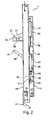
- FIG. 2 shows a movement phase in which the catch element 69, which is guided by the cam 70 in the guide slot 14, pivots in the latching portion 14b.
- the catch element 69 detaches from the driver 31, so that the pull-out rail 30 can continue to move forward with a pulse transmitted from the opening device 50, while the Catch member 69 is retained in the locking position 14b until further notice.
- the driving flap 33 on its steep engagement surface 38 earlier than the control flap 34 come into contact with the actuating arm 19, whereby the driving flap 33 is held in an engaged or driving position and the actuator arm 19 flips with continued forward movement of the drawer rail 30.
- the actuating arm 19 also hits the ramp surface 39 of the control flap 34. As a result, it is pivoted into the extension arm 32. Because the driving flap 33 is held by the actuating arm 19 in the engaged position, the pivoting of the control flap 34 only causes the spring 35 is pressed together. In this case, the spring is preferably too weak to release in a compressed state, the driving flap when moving the actuating arm 19 from engagement of the actuating arm 19.
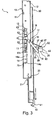
- FIG. 3 a state of the guide unit 1 is shown in a movement phase in which the Auslegearm 32 acts with the driving flap 33 on the actuating arm 19 of the actuating lever 16, while the actuating arm 19 presses the control flap 34 in the Auslegearm 32.
- the cam 70 is engaged in the locking portion 14b, while the carriage 62 and the housing 61 of the feeder 60 are displaced by the adjusting lever 16 in the insertion direction.
- FIG. 3 is the lever 16 as a result of entrainment by the pull-out rail 30 and the extension arm 32 already folded so far that the carriage 62 almost to the in FIG. 1 shown starting position is set back.
- the lever 16 and the driving flap are 33 just in contact with each other, the flipping is substantially complete.
- the actuating arm 19 can slide laterally past the driving flap 33 and pass underneath the control flap 34.
- the adjusting lever 16 with the rotary bearing 17 and the extension arm 32 are in particular adapted to the displaceable mounting 13, 62 of the retraction device 60 and the opening device 50 that by an extending movement of the extension arm 32 of the plunger 52 of the opening device 50 locked in a stable closed state is.
- the pull-out rail 30 can be moved and positioned freely from an extended position, in which the positioning lever 16 is folded over, essentially uninfluenced by the opening device 50 or the pull-in device 60 or the setting lever 16.
- the pull-out rail 30 can be extended so far until it is e.g. strikes at a maximum extendable position.
- Both flaps 33, 34 have, as in the FIG. 5 shown on the side lying in the insertion direction a comparatively flat rising ramp surface 42, so that the flaps 33, 34 are relatively easily displaced in a retracting movement and a driving of the actuating arm 19 by the flaps 33, 34 at retracting movements of the drawer rail 30 is prevented is.
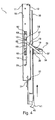
- the sliding ramp 39 is first reachable by the adjusting lever 16 when the actuating arm 19 in a position pointing in the opening direction, such as in the FIG. 4 shown is located.
- the surface of the slide ramp 39 is inclined in a manner such that the control lever 16 can push the control flap 34 upwards. Because in the position of the actuating lever 16 shown here, the actuating arm 19 does not exert any holding forces on the driving flap 33, the actuating arm 19 can lift the control flap 34 together with the driving flap 33 by means of the spring 34.
Landscapes
- Engineering & Computer Science (AREA)
- Mechanical Engineering (AREA)
- Drawers Of Furniture (AREA)
Applications Claiming Priority (1)
| Application Number | Priority Date | Filing Date | Title |
|---|---|---|---|
| DE202011104526U DE202011104526U1 (de) | 2011-08-17 | 2011-08-17 | Vorrichtung zur Bewegung eines bewegbaren Möbelteils, Führungseinheit und Möbel |
Publications (2)
| Publication Number | Publication Date |
|---|---|
| EP2559355A1 true EP2559355A1 (fr) | 2013-02-20 |
| EP2559355B1 EP2559355B1 (fr) | 2018-11-07 |
Family
ID=46758575
Family Applications (1)
| Application Number | Title | Priority Date | Filing Date |
|---|---|---|---|
| EP12005924.1A Not-in-force EP2559355B1 (fr) | 2011-08-17 | 2012-08-17 | Dispositif destiné à déplacer une pièce de meuble mobile, unité de guidage et meuble |
Country Status (2)
| Country | Link |
|---|---|
| EP (1) | EP2559355B1 (fr) |
| DE (1) | DE202011104526U1 (fr) |
Cited By (1)
| Publication number | Priority date | Publication date | Assignee | Title |
|---|---|---|---|---|
| CN114886270A (zh) * | 2022-06-28 | 2022-08-12 | 宣城市艺雪制冷设备有限公司 | 一种多窗口拿取物品式保鲜展示柜 |
Families Citing this family (1)
| Publication number | Priority date | Publication date | Assignee | Title |
|---|---|---|---|---|
| DE102017123613A1 (de) | 2017-10-11 | 2019-04-11 | Paul Hettich Gmbh & Co. Kg | Einzugsvorrichtung und Verfahren zum Öffnen und Schließen eines bewegbaren Möbelteils |
Citations (3)
| Publication number | Priority date | Publication date | Assignee | Title |
|---|---|---|---|---|
| DE19935120A1 (de) * | 1999-07-27 | 2001-02-15 | Bulthaup Gmbh & Co | Vorrichtung zum Öffnen und Schließen einer Schublade |
| DE202009005119U1 (de) * | 2009-08-07 | 2010-12-30 | Paul Hettich Gmbh & Co. Kg | Auszugsführung |
| EP2279680A1 (fr) * | 2009-07-28 | 2011-02-02 | Paul Hettich GmbH & Co. KG | Dispositif d'ouverture et de fermeture |
Family Cites Families (2)
| Publication number | Priority date | Publication date | Assignee | Title |
|---|---|---|---|---|
| AT8629U1 (de) * | 2004-09-13 | 2006-10-15 | Blum Gmbh Julius | Möbel mit einem bewegbaren möbelteil |
| ES2534501T3 (es) * | 2009-07-21 | 2015-04-23 | King Slide Works Co., Ltd. | Dispositivo automotor para componentes de muebles móviles |
-
2011
- 2011-08-17 DE DE202011104526U patent/DE202011104526U1/de not_active Expired - Lifetime
-
2012
- 2012-08-17 EP EP12005924.1A patent/EP2559355B1/fr not_active Not-in-force
Patent Citations (3)
| Publication number | Priority date | Publication date | Assignee | Title |
|---|---|---|---|---|
| DE19935120A1 (de) * | 1999-07-27 | 2001-02-15 | Bulthaup Gmbh & Co | Vorrichtung zum Öffnen und Schließen einer Schublade |
| EP2279680A1 (fr) * | 2009-07-28 | 2011-02-02 | Paul Hettich GmbH & Co. KG | Dispositif d'ouverture et de fermeture |
| DE202009005119U1 (de) * | 2009-08-07 | 2010-12-30 | Paul Hettich Gmbh & Co. Kg | Auszugsführung |
Cited By (2)
| Publication number | Priority date | Publication date | Assignee | Title |
|---|---|---|---|---|
| CN114886270A (zh) * | 2022-06-28 | 2022-08-12 | 宣城市艺雪制冷设备有限公司 | 一种多窗口拿取物品式保鲜展示柜 |
| CN114886270B (zh) * | 2022-06-28 | 2023-03-03 | 宣城市艺雪制冷设备有限公司 | 一种多窗口拿取物品式保鲜展示柜 |
Also Published As
| Publication number | Publication date |
|---|---|
| EP2559355B1 (fr) | 2018-11-07 |
| DE202011104526U1 (de) | 2012-11-19 |
Similar Documents
| Publication | Publication Date | Title |
|---|---|---|
| EP2793657B1 (fr) | Dispositif pour influencer le mouvement d'une partie de meuble, système de guidage pour guider le mouvement d'une partie de meuble et meuble | |
| DE102010031941B4 (de) | Möbelantrieb mit Touch-Latch-Vorrichtung | |
| EP2174572B1 (fr) | Dispositif d'ouverture et de fermeture pour un élément de coulissement | |
| EP2713820B1 (fr) | Dispositif de fixation servant à fixer un panneau de façade sur un tiroir | |
| EP3319483B1 (fr) | Dispositif d'entraînement destiné à un élément de meuble mobile | |
| EP3141153B1 (fr) | Dispositif de deplacement d'un element de meuble mobile dans un sens d'ouverture par rapport a un corps d'un meuble | |
| DE102017107461A1 (de) | Bewegungsanordnung | |
| WO2012159139A1 (fr) | Dispositif de fixation servant à fixer un panneau de façade sur un tiroir | |
| EP3133232B1 (fr) | Dispositif de deplacement d'un element de meuble mobile et meuble comprenant un dispositif de deplacement d'un element de meuble mobile | |
| EP3479735A1 (fr) | Dispositif de fixation pour fixer de manière détachable un panneau de façade sur un tiroir | |
| EP2142045A2 (fr) | Meuble et dispositif pour éjecter un élément de meuble | |
| DE202015104439U1 (de) | Vorrichtung zum Bewegen eines bewegbaren Möbelteils und Möbel | |
| DE102015117004B3 (de) | Bewegungseinrichtung für Schubladen | |
| EP4162133B1 (fr) | Système de guidage | |
| EP1374733A1 (fr) | Glissière pour tiroir | |
| WO2017036795A1 (fr) | Dispositif de positionnement de deux portes coulissantes et meuble | |
| WO2012084595A1 (fr) | Dispositif d'ouverture et de fermeture pour parties de meuble mobiles | |
| DE102010031940B4 (de) | Ausziehführung für Schubladen | |
| EP2713822B1 (fr) | Ensemble coulissant | |
| EP2534326B1 (fr) | Dispositif d'escamotage pour portes coulissants | |
| EP3675691B1 (fr) | Dispositif d'insertion permettant d'insérer une partie mobile d'un meuble ou d'un appareil ménager dans une position finale | |
| WO2018077521A1 (fr) | Dispositif d'éjection d'un élément de meuble mobile, meuble et procédé d'ouverture d'un élément de meuble mobile | |
| EP2559355B1 (fr) | Dispositif destiné à déplacer une pièce de meuble mobile, unité de guidage et meuble | |
| EP2710924B1 (fr) | Moyen de guidage pour guider un élément de meuble | |
| DE102011122269B4 (de) | Vorrichtung zur Bewegungsbeeinflussung |
Legal Events
| Date | Code | Title | Description |
|---|---|---|---|
| PUAI | Public reference made under article 153(3) epc to a published international application that has entered the european phase |
Free format text: ORIGINAL CODE: 0009012 |
|
| AK | Designated contracting states |
Kind code of ref document: A1 Designated state(s): AL AT BE BG CH CY CZ DE DK EE ES FI FR GB GR HR HU IE IS IT LI LT LU LV MC MK MT NL NO PL PT RO RS SE SI SK SM TR |
|
| AX | Request for extension of the european patent |
Extension state: BA ME |
|
| 17P | Request for examination filed |
Effective date: 20130812 |
|
| RBV | Designated contracting states (corrected) |
Designated state(s): AL AT BE BG CH CY CZ DE DK EE ES FI FR GB GR HR HU IE IS IT LI LT LU LV MC MK MT NL NO PL PT RO RS SE SI SK SM TR |
|
| R17P | Request for examination filed (corrected) |
Effective date: 20130812 |
|
| RBV | Designated contracting states (corrected) |
Designated state(s): AL AT BE BG CH CY CZ DE DK EE ES FI FR GB GR HR HU IE IS IT LI LT LU LV MC MK MT NL NO PL PT RO RS SE SI SK SM TR |
|
| 17Q | First examination report despatched |
Effective date: 20140304 |
|
| STAA | Information on the status of an ep patent application or granted ep patent |
Free format text: STATUS: EXAMINATION IS IN PROGRESS |
|
| REG | Reference to a national code |
Ref country code: DE Ref legal event code: R079 Ref document number: 502012013752 Country of ref document: DE Free format text: PREVIOUS MAIN CLASS: A47B0088040000 Ipc: A47B0088470000 |
|
| GRAP | Despatch of communication of intention to grant a patent |
Free format text: ORIGINAL CODE: EPIDOSNIGR1 |
|
| STAA | Information on the status of an ep patent application or granted ep patent |
Free format text: STATUS: GRANT OF PATENT IS INTENDED |
|
| RIC1 | Information provided on ipc code assigned before grant |
Ipc: A47B 88/47 20170101AFI20180328BHEP |
|
| GRAJ | Information related to disapproval of communication of intention to grant by the applicant or resumption of examination proceedings by the epo deleted |
Free format text: ORIGINAL CODE: EPIDOSDIGR1 |
|
| STAA | Information on the status of an ep patent application or granted ep patent |
Free format text: STATUS: EXAMINATION IS IN PROGRESS |
|
| INTG | Intention to grant announced |
Effective date: 20180426 |
|
| GRAP | Despatch of communication of intention to grant a patent |
Free format text: ORIGINAL CODE: EPIDOSNIGR1 |
|
| STAA | Information on the status of an ep patent application or granted ep patent |
Free format text: STATUS: GRANT OF PATENT IS INTENDED |
|
| INTC | Intention to grant announced (deleted) | ||
| INTG | Intention to grant announced |
Effective date: 20180613 |
|
| GRAS | Grant fee paid |
Free format text: ORIGINAL CODE: EPIDOSNIGR3 |
|
| GRAA | (expected) grant |
Free format text: ORIGINAL CODE: 0009210 |
|
| STAA | Information on the status of an ep patent application or granted ep patent |
Free format text: STATUS: THE PATENT HAS BEEN GRANTED |
|
| AK | Designated contracting states |
Kind code of ref document: B1 Designated state(s): AL AT BE BG CH CY CZ DE DK EE ES FI FR GB GR HR HU IE IS IT LI LT LU LV MC MK MT NL NO PL PT RO RS SE SI SK SM TR |
|
| REG | Reference to a national code |
Ref country code: GB Ref legal event code: FG4D Free format text: NOT ENGLISH |
|
| REG | Reference to a national code |
Ref country code: CH Ref legal event code: EP Ref country code: AT Ref legal event code: REF Ref document number: 1061074 Country of ref document: AT Kind code of ref document: T Effective date: 20181115 |
|
| REG | Reference to a national code |
Ref country code: IE Ref legal event code: FG4D Free format text: LANGUAGE OF EP DOCUMENT: GERMAN |
|
| REG | Reference to a national code |
Ref country code: DE Ref legal event code: R096 Ref document number: 502012013752 Country of ref document: DE |
|
| REG | Reference to a national code |
Ref country code: NL Ref legal event code: MP Effective date: 20181107 |
|
| REG | Reference to a national code |
Ref country code: LT Ref legal event code: MG4D |
|
| PG25 | Lapsed in a contracting state [announced via postgrant information from national office to epo] |
Ref country code: ES Free format text: LAPSE BECAUSE OF FAILURE TO SUBMIT A TRANSLATION OF THE DESCRIPTION OR TO PAY THE FEE WITHIN THE PRESCRIBED TIME-LIMIT Effective date: 20181107 Ref country code: LV Free format text: LAPSE BECAUSE OF FAILURE TO SUBMIT A TRANSLATION OF THE DESCRIPTION OR TO PAY THE FEE WITHIN THE PRESCRIBED TIME-LIMIT Effective date: 20181107 Ref country code: LT Free format text: LAPSE BECAUSE OF FAILURE TO SUBMIT A TRANSLATION OF THE DESCRIPTION OR TO PAY THE FEE WITHIN THE PRESCRIBED TIME-LIMIT Effective date: 20181107 Ref country code: HR Free format text: LAPSE BECAUSE OF FAILURE TO SUBMIT A TRANSLATION OF THE DESCRIPTION OR TO PAY THE FEE WITHIN THE PRESCRIBED TIME-LIMIT Effective date: 20181107 Ref country code: BG Free format text: LAPSE BECAUSE OF FAILURE TO SUBMIT A TRANSLATION OF THE DESCRIPTION OR TO PAY THE FEE WITHIN THE PRESCRIBED TIME-LIMIT Effective date: 20190207 Ref country code: IS Free format text: LAPSE BECAUSE OF FAILURE TO SUBMIT A TRANSLATION OF THE DESCRIPTION OR TO PAY THE FEE WITHIN THE PRESCRIBED TIME-LIMIT Effective date: 20190307 Ref country code: FI Free format text: LAPSE BECAUSE OF FAILURE TO SUBMIT A TRANSLATION OF THE DESCRIPTION OR TO PAY THE FEE WITHIN THE PRESCRIBED TIME-LIMIT Effective date: 20181107 Ref country code: NO Free format text: LAPSE BECAUSE OF FAILURE TO SUBMIT A TRANSLATION OF THE DESCRIPTION OR TO PAY THE FEE WITHIN THE PRESCRIBED TIME-LIMIT Effective date: 20190207 |
|
| PG25 | Lapsed in a contracting state [announced via postgrant information from national office to epo] |
Ref country code: SE Free format text: LAPSE BECAUSE OF FAILURE TO SUBMIT A TRANSLATION OF THE DESCRIPTION OR TO PAY THE FEE WITHIN THE PRESCRIBED TIME-LIMIT Effective date: 20181107 Ref country code: NL Free format text: LAPSE BECAUSE OF FAILURE TO SUBMIT A TRANSLATION OF THE DESCRIPTION OR TO PAY THE FEE WITHIN THE PRESCRIBED TIME-LIMIT Effective date: 20181107 Ref country code: GR Free format text: LAPSE BECAUSE OF FAILURE TO SUBMIT A TRANSLATION OF THE DESCRIPTION OR TO PAY THE FEE WITHIN THE PRESCRIBED TIME-LIMIT Effective date: 20190208 Ref country code: RS Free format text: LAPSE BECAUSE OF FAILURE TO SUBMIT A TRANSLATION OF THE DESCRIPTION OR TO PAY THE FEE WITHIN THE PRESCRIBED TIME-LIMIT Effective date: 20181107 Ref country code: AL Free format text: LAPSE BECAUSE OF FAILURE TO SUBMIT A TRANSLATION OF THE DESCRIPTION OR TO PAY THE FEE WITHIN THE PRESCRIBED TIME-LIMIT Effective date: 20181107 Ref country code: PT Free format text: LAPSE BECAUSE OF FAILURE TO SUBMIT A TRANSLATION OF THE DESCRIPTION OR TO PAY THE FEE WITHIN THE PRESCRIBED TIME-LIMIT Effective date: 20190307 |
|
| PG25 | Lapsed in a contracting state [announced via postgrant information from national office to epo] |
Ref country code: DK Free format text: LAPSE BECAUSE OF FAILURE TO SUBMIT A TRANSLATION OF THE DESCRIPTION OR TO PAY THE FEE WITHIN THE PRESCRIBED TIME-LIMIT Effective date: 20181107 Ref country code: IT Free format text: LAPSE BECAUSE OF FAILURE TO SUBMIT A TRANSLATION OF THE DESCRIPTION OR TO PAY THE FEE WITHIN THE PRESCRIBED TIME-LIMIT Effective date: 20181107 Ref country code: CZ Free format text: LAPSE BECAUSE OF FAILURE TO SUBMIT A TRANSLATION OF THE DESCRIPTION OR TO PAY THE FEE WITHIN THE PRESCRIBED TIME-LIMIT Effective date: 20181107 Ref country code: PL Free format text: LAPSE BECAUSE OF FAILURE TO SUBMIT A TRANSLATION OF THE DESCRIPTION OR TO PAY THE FEE WITHIN THE PRESCRIBED TIME-LIMIT Effective date: 20181107 |
|
| REG | Reference to a national code |
Ref country code: DE Ref legal event code: R097 Ref document number: 502012013752 Country of ref document: DE |
|
| PG25 | Lapsed in a contracting state [announced via postgrant information from national office to epo] |
Ref country code: SK Free format text: LAPSE BECAUSE OF FAILURE TO SUBMIT A TRANSLATION OF THE DESCRIPTION OR TO PAY THE FEE WITHIN THE PRESCRIBED TIME-LIMIT Effective date: 20181107 Ref country code: RO Free format text: LAPSE BECAUSE OF FAILURE TO SUBMIT A TRANSLATION OF THE DESCRIPTION OR TO PAY THE FEE WITHIN THE PRESCRIBED TIME-LIMIT Effective date: 20181107 Ref country code: SM Free format text: LAPSE BECAUSE OF FAILURE TO SUBMIT A TRANSLATION OF THE DESCRIPTION OR TO PAY THE FEE WITHIN THE PRESCRIBED TIME-LIMIT Effective date: 20181107 Ref country code: EE Free format text: LAPSE BECAUSE OF FAILURE TO SUBMIT A TRANSLATION OF THE DESCRIPTION OR TO PAY THE FEE WITHIN THE PRESCRIBED TIME-LIMIT Effective date: 20181107 |
|
| PLBE | No opposition filed within time limit |
Free format text: ORIGINAL CODE: 0009261 |
|
| STAA | Information on the status of an ep patent application or granted ep patent |
Free format text: STATUS: NO OPPOSITION FILED WITHIN TIME LIMIT |
|
| 26N | No opposition filed |
Effective date: 20190808 |
|
| PG25 | Lapsed in a contracting state [announced via postgrant information from national office to epo] |
Ref country code: SI Free format text: LAPSE BECAUSE OF FAILURE TO SUBMIT A TRANSLATION OF THE DESCRIPTION OR TO PAY THE FEE WITHIN THE PRESCRIBED TIME-LIMIT Effective date: 20181107 |
|
| PG25 | Lapsed in a contracting state [announced via postgrant information from national office to epo] |
Ref country code: TR Free format text: LAPSE BECAUSE OF FAILURE TO SUBMIT A TRANSLATION OF THE DESCRIPTION OR TO PAY THE FEE WITHIN THE PRESCRIBED TIME-LIMIT Effective date: 20181107 |
|
| GBPC | Gb: european patent ceased through non-payment of renewal fee |
Effective date: 20190817 |
|
| PG25 | Lapsed in a contracting state [announced via postgrant information from national office to epo] |
Ref country code: MC Free format text: LAPSE BECAUSE OF FAILURE TO SUBMIT A TRANSLATION OF THE DESCRIPTION OR TO PAY THE FEE WITHIN THE PRESCRIBED TIME-LIMIT Effective date: 20181107 Ref country code: LI Free format text: LAPSE BECAUSE OF NON-PAYMENT OF DUE FEES Effective date: 20190831 Ref country code: LU Free format text: LAPSE BECAUSE OF NON-PAYMENT OF DUE FEES Effective date: 20190817 Ref country code: CH Free format text: LAPSE BECAUSE OF NON-PAYMENT OF DUE FEES Effective date: 20190831 |
|
| REG | Reference to a national code |
Ref country code: BE Ref legal event code: MM Effective date: 20190831 |
|
| PG25 | Lapsed in a contracting state [announced via postgrant information from national office to epo] |
Ref country code: FR Free format text: LAPSE BECAUSE OF NON-PAYMENT OF DUE FEES Effective date: 20190831 Ref country code: IE Free format text: LAPSE BECAUSE OF NON-PAYMENT OF DUE FEES Effective date: 20190817 |
|
| PG25 | Lapsed in a contracting state [announced via postgrant information from national office to epo] |
Ref country code: GB Free format text: LAPSE BECAUSE OF NON-PAYMENT OF DUE FEES Effective date: 20190817 Ref country code: BE Free format text: LAPSE BECAUSE OF NON-PAYMENT OF DUE FEES Effective date: 20190831 |
|
| PG25 | Lapsed in a contracting state [announced via postgrant information from national office to epo] |
Ref country code: CY Free format text: LAPSE BECAUSE OF FAILURE TO SUBMIT A TRANSLATION OF THE DESCRIPTION OR TO PAY THE FEE WITHIN THE PRESCRIBED TIME-LIMIT Effective date: 20181107 |
|
| PG25 | Lapsed in a contracting state [announced via postgrant information from national office to epo] |
Ref country code: HU Free format text: LAPSE BECAUSE OF FAILURE TO SUBMIT A TRANSLATION OF THE DESCRIPTION OR TO PAY THE FEE WITHIN THE PRESCRIBED TIME-LIMIT; INVALID AB INITIO Effective date: 20120817 Ref country code: MT Free format text: LAPSE BECAUSE OF FAILURE TO SUBMIT A TRANSLATION OF THE DESCRIPTION OR TO PAY THE FEE WITHIN THE PRESCRIBED TIME-LIMIT Effective date: 20181107 |
|
| PG25 | Lapsed in a contracting state [announced via postgrant information from national office to epo] |
Ref country code: MK Free format text: LAPSE BECAUSE OF FAILURE TO SUBMIT A TRANSLATION OF THE DESCRIPTION OR TO PAY THE FEE WITHIN THE PRESCRIBED TIME-LIMIT Effective date: 20181107 |
|
| PGFP | Annual fee paid to national office [announced via postgrant information from national office to epo] |
Ref country code: DE Payment date: 20220627 Year of fee payment: 11 Ref country code: AT Payment date: 20220628 Year of fee payment: 11 |
|
| REG | Reference to a national code |
Ref country code: DE Ref legal event code: R119 Ref document number: 502012013752 Country of ref document: DE |
|
| REG | Reference to a national code |
Ref country code: AT Ref legal event code: MM01 Ref document number: 1061074 Country of ref document: AT Kind code of ref document: T Effective date: 20230817 |
|
| PG25 | Lapsed in a contracting state [announced via postgrant information from national office to epo] |
Ref country code: AT Free format text: LAPSE BECAUSE OF NON-PAYMENT OF DUE FEES Effective date: 20230817 |
|
| PG25 | Lapsed in a contracting state [announced via postgrant information from national office to epo] |
Ref country code: AT Free format text: LAPSE BECAUSE OF NON-PAYMENT OF DUE FEES Effective date: 20230817 |
|
| PG25 | Lapsed in a contracting state [announced via postgrant information from national office to epo] |
Ref country code: DE Free format text: LAPSE BECAUSE OF NON-PAYMENT OF DUE FEES Effective date: 20240301 |