EP2559567A2 - Composant de vélo et procédé de montage d'un composant de vélo - Google Patents
Composant de vélo et procédé de montage d'un composant de vélo Download PDFInfo
- Publication number
- EP2559567A2 EP2559567A2 EP12005882A EP12005882A EP2559567A2 EP 2559567 A2 EP2559567 A2 EP 2559567A2 EP 12005882 A EP12005882 A EP 12005882A EP 12005882 A EP12005882 A EP 12005882A EP 2559567 A2 EP2559567 A2 EP 2559567A2
- Authority
- EP
- European Patent Office
- Prior art keywords
- hub
- hub shell
- spoke
- unit
- bicycle component
- Prior art date
- Legal status (The legal status is an assumption and is not a legal conclusion. Google has not performed a legal analysis and makes no representation as to the accuracy of the status listed.)
- Withdrawn
Links
- 238000000034 method Methods 0.000 title claims abstract description 9
- 238000007789 sealing Methods 0.000 claims abstract description 44
- 230000007613 environmental effect Effects 0.000 description 6
- 238000003780 insertion Methods 0.000 description 5
- 230000037431 insertion Effects 0.000 description 5
- 238000010276 construction Methods 0.000 description 3
- 238000009434 installation Methods 0.000 description 3
- 239000006096 absorbing agent Substances 0.000 description 2
- 230000005540 biological transmission Effects 0.000 description 2
- 238000011161 development Methods 0.000 description 2
- 230000018109 developmental process Effects 0.000 description 2
- 239000000428 dust Substances 0.000 description 2
- 229920001971 elastomer Polymers 0.000 description 2
- 239000000806 elastomer Substances 0.000 description 2
- 210000003746 feather Anatomy 0.000 description 2
- 230000035939 shock Effects 0.000 description 2
- 229910000831 Steel Inorganic materials 0.000 description 1
- 230000004308 accommodation Effects 0.000 description 1
- 239000002131 composite material Substances 0.000 description 1
- 230000001419 dependent effect Effects 0.000 description 1
- 238000013461 design Methods 0.000 description 1
- 239000013013 elastic material Substances 0.000 description 1
- 239000000835 fiber Substances 0.000 description 1
- 230000003993 interaction Effects 0.000 description 1
- 238000002386 leaching Methods 0.000 description 1
- 239000003562 lightweight material Substances 0.000 description 1
- 239000000314 lubricant Substances 0.000 description 1
- 238000012423 maintenance Methods 0.000 description 1
- 239000002184 metal Substances 0.000 description 1
- 210000003205 muscle Anatomy 0.000 description 1
- 230000036316 preload Effects 0.000 description 1
- 239000011343 solid material Substances 0.000 description 1
- 239000010959 steel Substances 0.000 description 1
- 238000013519 translation Methods 0.000 description 1
- XLYOFNOQVPJJNP-UHFFFAOYSA-N water Substances O XLYOFNOQVPJJNP-UHFFFAOYSA-N 0.000 description 1
Images

Classifications
-
- B—PERFORMING OPERATIONS; TRANSPORTING
- B60—VEHICLES IN GENERAL
- B60B—VEHICLE WHEELS; CASTORS; AXLES FOR WHEELS OR CASTORS; INCREASING WHEEL ADHESION
- B60B27/00—Hubs
- B60B27/02—Hubs adapted to be rotatably arranged on axle
- B60B27/023—Hubs adapted to be rotatably arranged on axle specially adapted for bicycles
-
- B—PERFORMING OPERATIONS; TRANSPORTING
- B60—VEHICLES IN GENERAL
- B60B—VEHICLE WHEELS; CASTORS; AXLES FOR WHEELS OR CASTORS; INCREASING WHEEL ADHESION
- B60B1/00—Spoked wheels; Spokes thereof
- B60B1/003—Spoked wheels; Spokes thereof specially adapted for bicycles
-
- B—PERFORMING OPERATIONS; TRANSPORTING
- B60—VEHICLES IN GENERAL
- B60B—VEHICLE WHEELS; CASTORS; AXLES FOR WHEELS OR CASTORS; INCREASING WHEEL ADHESION
- B60B1/00—Spoked wheels; Spokes thereof
- B60B1/02—Wheels with wire or other tension spokes
-
- B—PERFORMING OPERATIONS; TRANSPORTING
- B60—VEHICLES IN GENERAL
- B60B—VEHICLE WHEELS; CASTORS; AXLES FOR WHEELS OR CASTORS; INCREASING WHEEL ADHESION
- B60B1/00—Spoked wheels; Spokes thereof
- B60B1/02—Wheels with wire or other tension spokes
- B60B1/04—Attaching spokes to rim or hub
- B60B1/041—Attaching spokes to rim or hub of bicycle wheels
-
- B—PERFORMING OPERATIONS; TRANSPORTING
- B60—VEHICLES IN GENERAL
- B60B—VEHICLE WHEELS; CASTORS; AXLES FOR WHEELS OR CASTORS; INCREASING WHEEL ADHESION
- B60B1/00—Spoked wheels; Spokes thereof
- B60B1/02—Wheels with wire or other tension spokes
- B60B1/04—Attaching spokes to rim or hub
- B60B1/042—Attaching spokes to hub
-
- B—PERFORMING OPERATIONS; TRANSPORTING
- B60—VEHICLES IN GENERAL
- B60B—VEHICLE WHEELS; CASTORS; AXLES FOR WHEELS OR CASTORS; INCREASING WHEEL ADHESION
- B60B27/00—Hubs
- B60B27/0015—Hubs for driven wheels
- B60B27/0021—Hubs for driven wheels characterised by torque transmission means from drive axle
- B60B27/0031—Hubs for driven wheels characterised by torque transmission means from drive axle of the axial type, e.g. front teeth
-
- B—PERFORMING OPERATIONS; TRANSPORTING
- B60—VEHICLES IN GENERAL
- B60B—VEHICLE WHEELS; CASTORS; AXLES FOR WHEELS OR CASTORS; INCREASING WHEEL ADHESION
- B60B27/00—Hubs
- B60B27/0073—Hubs characterised by sealing means
-
- B—PERFORMING OPERATIONS; TRANSPORTING
- B60—VEHICLES IN GENERAL
- B60B—VEHICLE WHEELS; CASTORS; AXLES FOR WHEELS OR CASTORS; INCREASING WHEEL ADHESION
- B60B27/00—Hubs
- B60B27/02—Hubs adapted to be rotatably arranged on axle
- B60B27/04—Hubs adapted to be rotatably arranged on axle housing driving means, e.g. sprockets
- B60B27/047—Hubs adapted to be rotatably arranged on axle housing driving means, e.g. sprockets comprising a freewheel mechanisms
-
- B—PERFORMING OPERATIONS; TRANSPORTING
- B60—VEHICLES IN GENERAL
- B60B—VEHICLE WHEELS; CASTORS; AXLES FOR WHEELS OR CASTORS; INCREASING WHEEL ADHESION
- B60B31/00—Apparatus or tools for assembling or disassembling wheels
- B60B31/005—Apparatus or tools for assembling or disassembling wheels especially for spoked wheels
-
- F—MECHANICAL ENGINEERING; LIGHTING; HEATING; WEAPONS; BLASTING
- F16—ENGINEERING ELEMENTS AND UNITS; GENERAL MEASURES FOR PRODUCING AND MAINTAINING EFFECTIVE FUNCTIONING OF MACHINES OR INSTALLATIONS; THERMAL INSULATION IN GENERAL
- F16D—COUPLINGS FOR TRANSMITTING ROTATION; CLUTCHES; BRAKES
- F16D2300/00—Special features for couplings or clutches
- F16D2300/08—Details or arrangements of sealings not provided for in group F16D3/84
-
- F—MECHANICAL ENGINEERING; LIGHTING; HEATING; WEAPONS; BLASTING
- F16—ENGINEERING ELEMENTS AND UNITS; GENERAL MEASURES FOR PRODUCING AND MAINTAINING EFFECTIVE FUNCTIONING OF MACHINES OR INSTALLATIONS; THERMAL INSULATION IN GENERAL
- F16D—COUPLINGS FOR TRANSMITTING ROTATION; CLUTCHES; BRAKES
- F16D41/00—Freewheels or freewheel clutches
- F16D41/24—Freewheels or freewheel clutches specially adapted for cycles
-
- F—MECHANICAL ENGINEERING; LIGHTING; HEATING; WEAPONS; BLASTING
- F16—ENGINEERING ELEMENTS AND UNITS; GENERAL MEASURES FOR PRODUCING AND MAINTAINING EFFECTIVE FUNCTIONING OF MACHINES OR INSTALLATIONS; THERMAL INSULATION IN GENERAL
- F16D—COUPLINGS FOR TRANSMITTING ROTATION; CLUTCHES; BRAKES
- F16D41/00—Freewheels or freewheel clutches
- F16D41/24—Freewheels or freewheel clutches specially adapted for cycles
- F16D41/36—Freewheels or freewheel clutches specially adapted for cycles with clutching ring or disc axially shifted as a result of lost motion between actuating members
-
- Y—GENERAL TAGGING OF NEW TECHNOLOGICAL DEVELOPMENTS; GENERAL TAGGING OF CROSS-SECTIONAL TECHNOLOGIES SPANNING OVER SEVERAL SECTIONS OF THE IPC; TECHNICAL SUBJECTS COVERED BY FORMER USPC CROSS-REFERENCE ART COLLECTIONS [XRACs] AND DIGESTS
- Y10—TECHNICAL SUBJECTS COVERED BY FORMER USPC
- Y10T—TECHNICAL SUBJECTS COVERED BY FORMER US CLASSIFICATION
- Y10T29/00—Metal working
- Y10T29/49—Method of mechanical manufacture
- Y10T29/49481—Wheel making
- Y10T29/49492—Land wheel
- Y10T29/49506—Tensioned spoke type wheel making
Definitions
- the present invention relates to a bicycle component and a method for assembling a bicycle component, wherein the bicycle component is provided for at least partially human-powered vehicles and in particular two-wheeled vehicles.
- a bicycle component is designed in particular as a hub and can be designed both as a front hub and as a rear hub.
- Hubs usually have a hub shell which is rotatably supported by two or more bearings relative to the fixed hub axle.
- seals are usually provided to protect the bearings from environmental entrapments.
- the weight of the components is also an important parameter.
- Rear hubs usually have a rotor on which a pinion pack or a plurality of individual pinions arranged be able to provide the user with a variety of translation variations.
- a freewheel is provided regularly, which provides for a reliable transmission of the driving force from the rotor to the hub shell, while the freewheel decouples the rotor from the hub shell when the user just does not step downhill, for example, or backwards, for example when driving downhill.
- the reliable operation of the freewheel is of great importance for driving safety. Therefore, the freewheel is usually protected by a separate seal from environmental influences.
- a hub which has a toothed disc freewheel.
- a toothed disc freewheel two toothed disks each provided with an axial toothing are preloaded on one another in order to transmit the driving torque from the one toothed disk to the other toothed disk in the engaged state. If no drive torque is being applied or the user is backing up, for example, the axial gears will slide along one another and disengage against the force of the bias, thereby realizing a freewheeling function.
- a toothed disc of the toothed disc freewheel is usually arranged inside the rotor, while the other toothed disc transmits the applied torque to the hub shell. Since the hub shell is usually made of a lighter and less solid material, the toothed disc in the hub shell is therefore accommodated in this known hub within a threaded ring which is screwed into the hub shell. The threaded ring can be replaced when worn, increasing the service life of the hub.
- the seal between the Hub housing and the rotor to protect the freewheel from water and dust.
- This hub works reliably, but requires a certain effort in the design and installation, since the individual components must be installed in the confined spaces reliably and easily.
- a bicycle component according to the invention is intended for use on at least partially muscle-operated vehicles and in particular two-wheeled vehicles.
- the bicycle component comprises a plurality of units, of which at least one unit is designed as a fixed unit and at least one unit as a rotatable unit.
- a fixed unit forms at least part of a hub axle.
- a rotatable unit is formed as a hub shell.
- the hub shell is provided with at least one spoke receiver for attachment of at least one spoke.
- the hub shell is rotatably supported by at least one bearing with respect to the hub axle.
- At least one separate and attached to at least one of the plurality of units seal cover is provided on which an at least partially sealed passage opening is provided for at least one unit, which unit relative is rotatable to the hub shell.
- the bicycle component according to the invention has many advantages.
- the particular designed as a hub bicycle component is simple and easy to assemble. Characterized in that a separate sealing cover is provided for sealing the hub shell to the outside, the assembly and the structure is simplified.
- the seal cover for example, be designed as a cover or sealing ring.
- the sealing cover has at least and in particular exactly one through opening through which at least one unit of the bicycle component is carried out in the intended assembly.
- the passage opening on the seal cover is at least partially sealed in order to protect in particular the interior of the bicycle component from environmental influences.
- the seal cover is arranged co-rotating with the hub shell.
- the seal cover is particularly firmly connected to the hub shell.
- the seal cover is preferably provided detachably.
- the seal cover or at least one seal cover has at least one sealing unit.
- the sealing unit may be designed as a complete seal or together with another sealing unit result in a seal.
- At least one sealing cover of the at least one sealing cover has a labyrinth seal as a sealing unit and / or at least one elastomeric seal as a sealing unit. It is also possible that the seal cover a non-contact labyrinth seal and a contacting seal made of an elastic material.
- At least one sealing cover of the at least one sealing cover is screwed to the hub shell.
- the seal cover is preferably provided with an external thread and is screwed into an internal thread of the hub shell.
- the seal cover has an internal thread which is screwed onto an external thread on the hub shell. Screwing the seal cover with the hub shell leads to a captive recording of the seal cover on the hub shell.
- other components can be secured by the seal cover to the hub shell.
- the seal cover has, for example, a circumferential groove or the like, in which an O-ring is inserted, so that the seal cover is received by clamping in the hub shell.
- At least one guide means is provided in the hub shell, which cooperates with at least one guide means on the seal cover to ensure a defined recording of the seal cover to the hub shell.
- a shoulder may be provided which leads to a defined and in particular centered recording of the seal cover on the hub shell, when the seal cover is pushed with a cylindrically shaped part in the hub shell.
- Such a defined guide and receiving the seal cover on the hub shell is particularly advantageous when the seal cover is screwed into the hub shell and is provided with a seal. Since a thread regularly has a certain radial clearance, such a guide means a precisely defined positioning of the seal cover is achieved on the hub shell, which is particularly important for a sealing function.
- the or at least one sealing cover is fastened in particular to a rotatable unit and in particular to the hub shell. It is also possible to attach the or at least one seal cover to a stationary unit.
- the seal cover may be attached to the hub axle or an adapter ring or similar device.
- the bicycle component has a rotor as a rotatable unit on which at least one pinion or a sprocket set is to be arranged. It is also possible to attach the or at least one seal cover to the rotor or another rotatable unit.
- the bicycle component may be formed as a rear hub of a bicycle. Then it is preferred that a seal cover is provided which has a sealing unit for sealing the rotatable hub shell with respect to the rotatable rotor and the environment.
- a freewheel and in particular a toothed disc freewheel is preferably provided, which comprises at least one toothed disk, which is received in a rotationally fixed and axially displaceable manner in an engagement component.
- the toothed disc freewheel has two axially movable toothed disks which are each received in a rotationally fixed and axially displaceable manner in an engagement component.
- an engagement component is provided in the hub shell.
- the other engagement component may be provided as a separate part on the rotor or may be formed by the rotor.
- an axially movable toothed disc is received in an engagement component in the hub shell, while the other axial toothing is formed directly as a spur toothing on the rotor.
- At least one toothed disk of the toothed disc freewheel has a non-circular outer contour and can, for example, via a Have external toothing, which is arranged rotationally fixed and axially displaceable in a corresponding internal toothing of the engagement component.
- An engagement component is preferably screwed into the hub shell.
- this engagement component may be provided as a threaded ring with a non-circular inner contour, which coincides with a non-circular outer contour of the toothed disc, so that a rotationally fixed reception of the toothed disc in the engagement component and an axial displaceability of the toothed disc with respect to the engagement component is ensured.
- the engagement component has a non-circular outer contour, which is inserted into a corresponding non-circular inner contour of the hub shell, so that the engagement component is rotatably received in the hub shell.
- an axial disassembly is possible.
- the engagement component is secured in the axial direction by the seal cover.
- the seal cover can also be referred to as a retaining cover or hub cover.
- the seal cover can be screwed into the hub shell while axially fixing the engagement component in the hub shell.
- the hub shell may be formed in one piece or else consist of several separate parts, which together form a rotatable unit.
- the hub shell has at least one and in particular two hub flanges, wherein on at least one hub flange outwardly extending spoke openings are provided for spokes.
- the bicycle component is provided in particular for straight-pull spokes. It is preferred that the spoke openings are formed as spoke holes and designed to be closed all around. Such a construction is particularly stable and allows a lighter construction of the bicycle component, since only smaller wall thicknesses are needed. But it is also possible that the spoke openings are slotted side, so that the spokes can be inserted from the side in spoke openings.
- At least one receiving space for at least one inner spoke end is provided on the hub flange or the spoke receptacle so that the spoke head can be arranged in the receiving space.
- the receiving space is covered in particular by the seal cover.
- spoke body are flattened and having a knife-like structure.
- Such spokes have a significantly reduced flow resistance in the direction of travel.
- the spoke Due to the interaction of the receiving space on the hub shell for receiving the inner flattened spoke end and in particular of the flattened spoke head with the externally applied seal cover the spoke can be held against rotation, so that a low air resistance is ensured.
- an adapter ring is preferably arranged as a particular fixed unit at least at one end of the hub axle.
- an adapter ring is provided at each end of the hub axle.
- the adapter rings extend the hub axle and provide receiving sections for the dropouts. It is possible that at least one sealing ring is attached to at least one adapter ring.
- the hub body at least partially made of at least one lightweight material such as a light metal or fiber composite material.
- the toothed disks of a toothed disc freewheel are preferably made of steel.
- the inventive method is used for mounting a bicycle component.
- spokes are inserted into spoke openings of the hub shell, so that the radially inner spoke ends of the spokes are arranged in a receiving space on the hub shell.
- a seal cover is attached to the hub shell so that the spokes are captively received on the hub.
- the method according to the invention also has considerable advantages, since it allows easy and simple installation of a bicycle component.
- the spokes can be inserted through lateral slots in the spoke openings or the spokes are through the all-round closed spoke holes through the hub shell through to the outside performed so that the radially inner spoke ends or spoke heads are arranged in a receiving space of the hub shell.
- the particular flattened spoke heads can be fixed laterally by the seal cover, so that the spokes are taken against rotation on the hub.
- the dimensions of the receiving space are dimensioned so that the spokes have only a small margin after insertion into the hub shell. This allows for easier mounting of the wheel afterwards.
- the rotor When mounting a rear hub, the rotor is preferably pushed after the insertion of the spokes. As a result, more space can be made available in the hub, since, for example, the seal of the rotor is provided on the seal cover, which is fastened and screwed in only after the insertion of the spokes.
- the freewheel in the form of, for example, a toothed disc freewheel is provided there.
- the seal between the rotor and the hub shell expands axially outwardly in a conventional case. If now straight-pull spokes are to be used, then the spokes must be pushed radially from the inside into the spoke holes to the outside. This can interfere with conventional hubs seal. This can result in conventional hubs having to increase the outer diameter of the spoke flange so that the straight-pull spokes do not collide with the seal seat during linear insertion. This problem increases with the number of spokes and with an increasing spoke angle.
- the spokes can not be arranged because there the rotor with the sprocket set is arranged.
- the invention allows such a hub easier to construct and easier to assemble.
- spokes there is no annoying seal, as the seal is removed together with the seal cover. Only after assembly and the insertion of the spokes of the seal cover is placed and thus brought the seal in functional position.
- Fig. 1 is a designed as a two-wheel 50 and in particular as racing bike vehicle 70 shown in a schematic side view.
- the bicycle 50 is at least partially muscle operated and may have an electric auxiliary drive.
- the racing bike is shown in a highly schematic side view and has a front wheel 51 and a rear wheel 52 and a frame 53.
- a handlebar 56 is used for control and can be designed differently.
- other known embodiments are possible.
- a battery 58 may be provided below the saddle 57, which is used in particular in electro-assisted two-wheeled vehicles.
- a battery 58 may also be mounted at other locations on the frame or integrated into the frame or otherwise housed.
- the tire 60 may be designed as a tubeless tire and adhered to the rim 61, for example.
- the rim 61 is connected to the hub via spokes 27, respectively.
- the rear wheel 52 has a hub 1 according to the invention as a rear hub 3, while the front wheel has a hub according to the invention as a front hub 4.
- a mountain bike bicycle 50 is shown in a highly schematic side view, which has a front wheel 51 and a rear wheel 52, a frame 53, a spring-loaded front fork 54 and a rear shock absorber 54.
- disc brakes are provided on the rear wheel 52 .
- On the rear wheel 52 is a rear hub 3 according to the invention and on the front wheel 51 a front hub 4 according to the invention is provided.
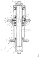
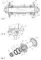
- Fig. 3 shows a highly schematic cross section through a bicycle component 1 according to the invention, which is designed here as a rear hub 3.
- the rear hub 3 is for use on the bicycle according to Fig. 1 or 2 suitable.
- the rear hub 3 has a hub axle 5 and a hub shell 6, which is rotatably supported by a plurality of bearings 7 with respect to the hub axle 5.
- adapter rings 30 and 31 are provided.
- a pulley freewheel 17 with toothed pulleys 18 and 19 is disposed between the rotor 16 and the hub shell 6 to transmit the driving torque of the rotor to the hub shell.
- the toothed disks 18 and 19 each have an axial toothing, via which the two toothed disks 18 and 19 are engaged with each other for torque transmission.
- the toothed disks 18 and 19 have non-circular outer cross-sections and are each received in a rotationally fixed and axially displaceable manner in engagement components 20 and 21, respectively.
- the engagement component 20 is formed by the rotor 16, while the engagement component 21 is provided as a separate part in the hub shell 6.
- the toothed discs 18 and 19 have here in the exemplary embodiment external toothing, with which they are rotatably but axially slidably received in the rotor 16 and in the engagement component 21.
- the hub shell 6 has hub flanges 24 and 25 on which spoke openings in the form of spoke holes 26 are provided.
- the hub 2 designed as a rear hub 3 is provided for the use of straight-pull spokes 27.
- spokes are elongate and are guided linearly through the spoke holes 26 until they are received, for example, with their spoke head in the receiving space 28 on the hub flanges 24 and 25, respectively.
- the spokes 27 are captively received by the seal cover 8 and 9, respectively.
- the seal covers 8 and 9 are screwed into the spoke flanges 24 and 25. As a result, the seal covers 8 and 9 hold the spokes 27 captive on the hub, so that the further assembly of the wheel is easier.
- sealing units 11 are provided to seal the hub shell 6 to the outside.
- the sealing unit 11 cooperates with the adapter ring 31 to protect the interior of the hub shell 6 and in particular the bearing 7 from environmental influences.
- the seal cover 8 on the side of the rotor 16 is screwed into the hub flange 24 and also has a sealing unit 11.
- the sealing unit 11 of the seal cover 8 cooperates with the rotor, so that both a labyrinth seal and a contacting elastomeric seal between the hub shell 6 and the rotor 16 is present.
- the interior of the hub shell 6 and in particular also the toothed disc freewheel 17 is protected against environmental influences.
- Fig. 3 designed as a hub 2 and here as a rear hub 3 bicycle component 1 with multiple units 35 to 38.
- the unit 36 is formed as a fixed unit 35, which consists of the adapters 30 and 31 and the hub axle 5 here. It is also possible that the fixed unit 35 consists only of the hub axle 5.
- the hub shell 6 forms a rotatable unit 37, which is mounted rotatably via bearings 7 on the hub axle 5.
- the hub shell 6 here has hub flanges 24, 25 as spoke holders 39 for fastening the spokes 27.
- seal cover 8 and 9 are provided.
- the seal cover 8 is here attached to the rotatable unit 37, but could also be attached to the rotatable unit 38.
- the seal cover 8 has a passage opening 40, through which the rotor 16 as a rotatable unit 38 and the fixed hub axle are performed as a fixed unit 36.
- the seal cover 8 seals here the interior of the hub 2 relative to the rotor 16 as a unit 38.
- the rotor 16 is arranged rotatably relative to the hub shell 6 or the hub shell 6 can be rotated freely in the freewheeling direction relative to the rotor 16.
- the seal cover 9 is also secured to the hub shell as a rotatable unit 37, but could also be attached to the adapter 31 and thus to the fixed unit 36.
- At least one separate and on a fixed or rotatable unit fastened seal cover may be provided on which an at least partially sealed passage opening is provided. Through the passage opening at least one rotatable relative to the hub shell stationary and / or rotatable unit is performed.
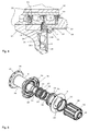
- Fig. 4 shows an enlarged section of the dot-dashed detail Fig. 3 , wherein the construction and arrangement of the seal cover on the hub shell 6 is even clearer.
- the toothed disc freewheel 17 has springs 32 and 33 which press axially from the outside on the toothed discs 18 and 19, respectively, in order to preload the toothed discs against each other.
- the sealing unit 11 here comprises sealing units 12 and 13, which realize the non-contact labyrinth seal and the contacting elastomeric seal 13.
- the seal cover 8 is screwed into the hub shell 6 via the thread 34.
- the seal cover 8 is centered on the guide means 14 in the form of a shoulder 10 in the hub shell and the guide means 15 in the form of a cylindrical piece of pipe on the seal cover eighth
- the representation according to Fig. 4 shows that after the removal of the rotor and the seal cover 8 or before mounting the seal cover 8 and the rotor 16, the spokes 27 can be easily inserted through the spoke holes 26, as much space is available. After inserting the spokes 27 into the receiving spaces 28 of the seal cover 8 is screwed, so that the hub 3 is equipped with the approximately star-shaped protruding spokes. Subsequently, the rotor 16 is applied. The guide means 14 and 15 ensure centering of the seal cover 8. The rotor is centered over the bearings 7, so that a well-defined positioning of the rotor to the seal cover 8 and the hub shell 6 takes place.
- Fig. 5 shows in an exploded view again the rear hub 3, wherein the recesses on the receiving spaces 28 of the hub flange 24 are clearly visible.
- the receiving space 28 it is also possible to form the receiving space 28 as a circumferential receiving space.
- the engagement component 21 has a non-circular outer contour 23 so that the engagement component 21 is held against rotation in the hub shell 6, which has a corresponding non-circular contour.
- the toothed discs 18 and 19 are provided with corresponding external teeth 22 or non-circular contours, which engage in a corresponding inner contour of the engagement components 20 and 21, so that the toothed discs 18 and 19 are rotatably but axially slidably received in the engagement components 20 and 21.
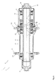
- a second embodiment of a bicycle component 1 according to the invention is explained, which is also designed here as a rear hub 3.
- the rear hub 3 has a hub axle 5 and a hub shell 6, which is provided with hub flanges 24 and 25.
- hub flanges 24 and 25 In the hub flanges here approximately axially arranged spoke holes 26 are provided for receiving conventional spokes.
- the hub shell 6 is rotatably supported relative to the hub axle 5 via a plurality of bearings 7.
- At the axial ends of adapter 30 and 31 are pushed, which are secured by grooves received in O-rings on the hub axle 5. With the adapter rings 30 and 31, the hub 2 is attached to the dropouts of a bicycle.
- the rear hub 3 has a toothed disc freewheel 17 with toothed discs 18 and 19, which via springs 32 and 33 in Axial direction are biased towards each other.
- a sealing cover 8 On the side of the rotor 16, which serves to receive a pinion package with a plurality of pinions, a sealing cover 8 is provided which has a sealing unit 11.
- the seal cover 8 is screwed by a thread 34 in the hub shell 6 and thus secures the axial position of the engagement component 21, on which the toothed disc 19 is rotatably and axially movably received.
- hub 2 is formed as a rear hub 3 and includes a plurality of units 35 to 38.
- the unit 36 is formed as a fixed unit 35, which consists of the adapters 30 and 31 and the hub axle 5 here.
- the hub shell 6 forms a rotatable unit 37, which is mounted rotatably via bearings 7 on the hub axle 5.
- seal cover 8 has a passage opening 40 for the rotor 16 as a rotatable unit 38.
- the seal cover 8 includes a through hole 40 for the fixed hub axle as a fixed unit 36.
- the seal cover 8 seals the interior of the hub 2 relative to the rotor 16 as a unit 38.
- the rotor 16 is arranged rotatably relative to the hub shell 6 or the hub shell 6 can be rotated freely in the freewheeling direction relative to the rotor 16.
- Fig. 7 shows the enlarged detail Fig. 6
- the screwed into the hub shell 6 with the thread 34 seal cover 8 carries sealing units 11, which here in conjunction with the rotor 16 form a non-contact labyrinth seal 12 and a contacting elastomeric seal 13.
- sealing units 11 here in conjunction with the rotor 16 form a non-contact labyrinth seal 12 and a contacting elastomeric seal 13.
- the interior of the hub shell 6 and in particular the toothed disc freewheel 17 protected against environmental influences.
- Via a shoulder 10 a centering of the seal cover 8 is effected.
- the engagement component 21 is in turn centered on the bearing 7 received on the hub 2.
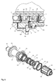
- Fig. 8 shows in an exploded view, the rear hub 3 acc. Fig. 6 , again showing the non-circular outer contour 23 of the engagement component 21.
- the sealing unit 11 may be attached as a separate part to the seal cover 8, so that the sealing unit 11 is replaceable if necessary.
- a bicycle component 1 which is designed here as a front hub 4.
- the front hub 4 after Fig. 9 has a hub axle 5 and a hub shell 6, which is rotatably supported by bearings 7 relative to the hub axle 5.
- adapter rings 30 and 31 are provided, which are inserted with their outer end in the dropouts of a bicycle fork or a bicycle frame.
- the Vorradnabe 4 is here provided with Speichenflanschen 24 and 25, are attached to the conventional spokes here. But it is also possible to attach straight-pull spokes, if appropriately designed differently shaped hub flanges 24 and 25.
- sealing cover 8 and 9 are provided, each having a sealing unit 11. It is possible that the sealing units are designed as labyrinth seals 12 or as elastomer seals 13 and provide a corresponding sealing function in cooperation with the hub axle.
- Fig. 10 shows the enlarged detail Fig. 9 ,
- the seal cover 8 is screwed into the hub shell 6.
- the seal cover 8 via an in an outer circumferential groove arranged O-ring in the hub body 6 to fix by clamping. Then, the seal cover 8 is held similarly in the hub shell 6 as the adapter rings 30 and 31 are clamped on the hub axle 5 held.
- Fig. 11 shows an exploded view of the front hub 4 from Fig. 9 , wherein also here the sealing unit 11 is provided interchangeable with the seal cover 9.
- the referring to the Fig. 9 to 11 illustrated hub 2 is formed as a front hub 4 and includes a plurality of units 35 to 37.
- the unit 36 as the hub axle 5 is formed as a fixed unit 35.
- the hub shell 6 forms a rotatable unit 37, which is mounted rotatably via bearings 7 on the hub axle 5.
- the hub axle 5 is performed here.
- the hub axle 5 is rotatably arranged relative to the hub shell 6.
Landscapes
- Engineering & Computer Science (AREA)
- Mechanical Engineering (AREA)
- Axle Suspensions And Sidecars For Cycles (AREA)
- Automatic Assembly (AREA)
- Sealing Using Fluids, Sealing Without Contact, And Removal Of Oil (AREA)
Applications Claiming Priority (1)
| Application Number | Priority Date | Filing Date | Title |
|---|---|---|---|
| DE102011110496A DE102011110496A1 (de) | 2011-08-17 | 2011-08-17 | Fahrradkomponente und Verfahren zur Montage einer Fahrradkomponente |
Publications (2)
| Publication Number | Publication Date |
|---|---|
| EP2559567A2 true EP2559567A2 (fr) | 2013-02-20 |
| EP2559567A3 EP2559567A3 (fr) | 2017-05-24 |
Family
ID=46758571
Family Applications (1)
| Application Number | Title | Priority Date | Filing Date |
|---|---|---|---|
| EP12005882.1A Withdrawn EP2559567A3 (fr) | 2011-08-17 | 2012-08-15 | Composant de vélo et procédé de montage d'un composant de vélo |
Country Status (3)
| Country | Link |
|---|---|
| US (1) | US20130088075A1 (fr) |
| EP (1) | EP2559567A3 (fr) |
| DE (1) | DE102011110496A1 (fr) |
Cited By (4)
| Publication number | Priority date | Publication date | Assignee | Title |
|---|---|---|---|---|
| EP3339054A1 (fr) * | 2016-12-23 | 2018-06-27 | Jochen Klieber | Moyeu de vélo ayant un dispositif d'étanchéité et une bride de serrage fendue |
| IT201900015270A1 (it) * | 2019-08-30 | 2021-03-02 | Alberto Gambarini | Anello rotante per proteggere dagli agenti esterni un cuscinetto di un mozzo e sistema equipaggiato con tale anello rotante per collegare rotazionalmente il mozzo a un perno del veicolo |
| US20240149616A1 (en) * | 2022-11-08 | 2024-05-09 | Dt Swiss Inc. | Hub, in particular for bicycles |
| EP4368850A1 (fr) * | 2022-11-08 | 2024-05-15 | DT Swiss AG | Moyeu, en particulier pour bicyclettes |
Families Citing this family (18)
| Publication number | Priority date | Publication date | Assignee | Title |
|---|---|---|---|---|
| DE102014117145A1 (de) * | 2014-11-24 | 2016-05-25 | Dt Swiss Ag | Fahrradkomponente mit einem Endanschlag und Endanschlag |
| US9649880B2 (en) | 2015-01-29 | 2017-05-16 | Shimano Inc. | Bicycle hub assembly |
| US9707801B2 (en) | 2015-10-01 | 2017-07-18 | Shimano Inc. | Bicycle hub assembly |
| US10625540B2 (en) | 2017-07-26 | 2020-04-21 | Dt Swiss Inc. | Hub, in particular for bicycles |
| US11400754B2 (en) * | 2016-07-26 | 2022-08-02 | Dt Swiss Inc. | Hub, in particular for bicycles |
| US10933691B2 (en) | 2017-07-26 | 2021-03-02 | Dt Swiss Inc. | Hub, in particular for bicycles |
| US10442245B2 (en) | 2016-07-26 | 2019-10-15 | Dt Swiss Inc. | Hub, in particular for bicycles |
| DE102017116948A1 (de) * | 2016-07-26 | 2018-02-01 | Dt Swiss Ag | Nabe insbesondere für Fahrräder |
| US10995806B2 (en) | 2017-07-26 | 2021-05-04 | Dt Swiss Inc. | Hub, in particular for bicycles |
| US10406856B2 (en) * | 2017-06-05 | 2019-09-10 | Chosen Co., Ltd | Bicycle hub apparatus |
| CN112249212A (zh) * | 2020-11-02 | 2021-01-22 | 贵州大学 | 一种三轮车的模块化前轮 |
| CN114683766A (zh) * | 2020-12-25 | 2022-07-01 | 株式会社岛野 | 用于人力车辆的轮毂 |
| TWI874628B (zh) * | 2021-03-29 | 2025-03-01 | 日商島野股份有限公司 | 自行車用後輪轂 |
| US12138958B2 (en) | 2021-12-22 | 2024-11-12 | Giant Manufacturing Co., Ltd. | Hub structure and hub for a bicycle |
| WO2024097274A1 (fr) * | 2022-11-02 | 2024-05-10 | Wilderness Trail Bikes Licensing, Inc. | Ensemble moyeu de roue de véhicule |
| DE102022129568A1 (de) * | 2022-11-08 | 2024-05-08 | Dt Swiss Ag | Nabe und Rotor insbesondere für Fahrräder |
| US20250303791A1 (en) * | 2024-03-28 | 2025-10-02 | Glory Wheel Enterprise Co., Ltd. | Hub for A Bicycle |
| DE102024125031A1 (de) * | 2024-09-02 | 2026-03-05 | Dt Swiss Ag | Fahrradkomponente |
Citations (1)
| Publication number | Priority date | Publication date | Assignee | Title |
|---|---|---|---|---|
| DE102007030190A1 (de) | 2006-07-07 | 2008-01-17 | Dt Swiss Ag | Hinterradnabe, insbesondere für Fahrräder |
Family Cites Families (10)
| Publication number | Priority date | Publication date | Assignee | Title |
|---|---|---|---|---|
| DE822347C (de) * | 1949-07-15 | 1951-11-26 | Werner Burwitz | Fahrrad mit gekapseltem Kegelradantrieb |
| DE936733C (de) * | 1953-10-18 | 1955-12-22 | Bayerische Motoren Werke Ag | Radgehaeuse aus Leichtmetall |
| US5626401A (en) * | 1994-05-17 | 1997-05-06 | Innovative Bicycle Components Company | Spoked wheel hub |
| DE29803667U1 (de) * | 1998-03-03 | 1998-04-23 | Kun Teng Industry & Co., Ltd., Taichung | Fahrradfreilaufnabe |
| DE29825016U1 (de) * | 1998-12-08 | 2004-05-19 | Dt Swiss Ag | Nabe, insbesondere für Fahrräder u.dgl. |
| FR2802853B1 (fr) * | 1999-12-23 | 2002-03-29 | Mavic Sa | Moyeu d'une roue a rayons notamment d'une roue de bicyclette |
| US6352314B1 (en) * | 2000-01-31 | 2002-03-05 | Shimano Inc. | Bicycle hub for disc brake |
| DE10034961A1 (de) * | 2000-07-19 | 2002-01-31 | Sram De Gmbh | Bremsnabe für ein Fahrzeug, insbesondere Rollstuhl |
| US7182410B2 (en) * | 2004-07-06 | 2007-02-27 | Shimano Inc. | Bicycle hub assembly |
| US8038225B2 (en) * | 2009-02-03 | 2011-10-18 | Joy Industrial Co., Ltd. | Bicycle hub assembly |
-
2011
- 2011-08-17 DE DE102011110496A patent/DE102011110496A1/de not_active Withdrawn
-
2012
- 2012-08-14 US US13/585,308 patent/US20130088075A1/en not_active Abandoned
- 2012-08-15 EP EP12005882.1A patent/EP2559567A3/fr not_active Withdrawn
Patent Citations (1)
| Publication number | Priority date | Publication date | Assignee | Title |
|---|---|---|---|---|
| DE102007030190A1 (de) | 2006-07-07 | 2008-01-17 | Dt Swiss Ag | Hinterradnabe, insbesondere für Fahrräder |
Cited By (4)
| Publication number | Priority date | Publication date | Assignee | Title |
|---|---|---|---|---|
| EP3339054A1 (fr) * | 2016-12-23 | 2018-06-27 | Jochen Klieber | Moyeu de vélo ayant un dispositif d'étanchéité et une bride de serrage fendue |
| IT201900015270A1 (it) * | 2019-08-30 | 2021-03-02 | Alberto Gambarini | Anello rotante per proteggere dagli agenti esterni un cuscinetto di un mozzo e sistema equipaggiato con tale anello rotante per collegare rotazionalmente il mozzo a un perno del veicolo |
| US20240149616A1 (en) * | 2022-11-08 | 2024-05-09 | Dt Swiss Inc. | Hub, in particular for bicycles |
| EP4368850A1 (fr) * | 2022-11-08 | 2024-05-15 | DT Swiss AG | Moyeu, en particulier pour bicyclettes |
Also Published As
| Publication number | Publication date |
|---|---|
| DE102011110496A1 (de) | 2013-02-21 |
| US20130088075A1 (en) | 2013-04-11 |
| EP2559567A3 (fr) | 2017-05-24 |
Similar Documents
| Publication | Publication Date | Title |
|---|---|---|
| EP2559567A2 (fr) | Composant de vélo et procédé de montage d'un composant de vélo | |
| EP3275692B1 (fr) | Moyeu, en particulier pour vélos | |
| DE102012016608B4 (de) | Antriebsnabe | |
| EP3023325B1 (fr) | Composant de vélo comprenant une butée et butée | |
| EP2497652B1 (fr) | Moyeu pour un vélo | |
| DE102011110199A1 (de) | Nabe | |
| DE102012017115A1 (de) | Fahrradvorderradnabe mit Torsionsrohr | |
| EP3275693B1 (fr) | Moyeu, en particulier pour vélos | |
| EP3517315B1 (fr) | Moyeu, en particulier pour vélos | |
| EP3275691B1 (fr) | Moyeu, en particulier pour vélos | |
| EP3862194B1 (fr) | Moyeu, en particulier pour bicyclettes | |
| DE102018101725A1 (de) | Nabe | |
| DE102010024474A1 (de) | Achssystem für ein Zweirad | |
| DE202018103890U1 (de) | Fahrradkomponente für ein wenigstens teilweise muskelbetriebenes Fahrrad | |
| EP1149000A1 (fr) | Moyeu destine notamment a des bicyclettes ou similaires | |
| DE102007026821B4 (de) | Nabe, insbesondere für Fahrräder und dergleichen | |
| DE102017007362A1 (de) | Elektromotor, insbesondere für Fahrzeug | |
| DE102019002629A1 (de) | Fahrzeugbremse | |
| DE102023126010A1 (de) | Nabe insbesondere für Fahrräder | |
| DE102008021895A1 (de) | Elektromechanische Lenkung | |
| EP4379228B1 (fr) | Moyeu, en particulier pour bicyclettes | |
| DE19861309B4 (de) | Nabe und Laufrad, insbesondere für Fahrräder und dergleichen | |
| DE102022129570A1 (de) | Nabe insbesondere für Fahrräder | |
| DE102022129568A1 (de) | Nabe und Rotor insbesondere für Fahrräder | |
| DE202015004678U1 (de) | Radnabe von Rädern eines einspurigen Zweirades mit Lenkstange und Hinterradantrieb und deren Befestigung im Fahrwerk wie Rahmen, Gabel, Schwinge |
Legal Events
| Date | Code | Title | Description |
|---|---|---|---|
| PUAI | Public reference made under article 153(3) epc to a published international application that has entered the european phase |
Free format text: ORIGINAL CODE: 0009012 |
|
| AK | Designated contracting states |
Kind code of ref document: A2 Designated state(s): AL AT BE BG CH CY CZ DE DK EE ES FI FR GB GR HR HU IE IS IT LI LT LU LV MC MK MT NL NO PL PT RO RS SE SI SK SM TR |
|
| AX | Request for extension of the european patent |
Extension state: BA ME |
|
| PUAL | Search report despatched |
Free format text: ORIGINAL CODE: 0009013 |
|
| AK | Designated contracting states |
Kind code of ref document: A3 Designated state(s): AL AT BE BG CH CY CZ DE DK EE ES FI FR GB GR HR HU IE IS IT LI LT LU LV MC MK MT NL NO PL PT RO RS SE SI SK SM TR |
|
| AX | Request for extension of the european patent |
Extension state: BA ME |
|
| RIC1 | Information provided on ipc code assigned before grant |
Ipc: B60B 1/02 20060101ALI20170420BHEP Ipc: B60B 27/00 20060101AFI20170420BHEP Ipc: F16D 41/24 20060101ALN20170420BHEP Ipc: B60B 31/00 20060101ALI20170420BHEP Ipc: B60B 1/04 20060101ALI20170420BHEP Ipc: B60B 1/00 20060101ALI20170420BHEP Ipc: B60B 27/02 20060101ALI20170420BHEP Ipc: B60B 27/04 20060101ALI20170420BHEP |
|
| 17P | Request for examination filed |
Effective date: 20171121 |
|
| RBV | Designated contracting states (corrected) |
Designated state(s): AL AT BE BG CH CY CZ DE DK EE ES FI FR GB GR HR HU IE IS IT LI LT LU LV MC MK MT NL NO PL PT RO RS SE SI SK SM TR |
|
| RAP1 | Party data changed (applicant data changed or rights of an application transferred) |
Owner name: DT SWISS AG |
|
| GRAP | Despatch of communication of intention to grant a patent |
Free format text: ORIGINAL CODE: EPIDOSNIGR1 |
|
| STAA | Information on the status of an ep patent application or granted ep patent |
Free format text: STATUS: GRANT OF PATENT IS INTENDED |
|
| RIC1 | Information provided on ipc code assigned before grant |
Ipc: B60B 27/04 20060101ALI20200506BHEP Ipc: B60B 31/00 20060101ALI20200506BHEP Ipc: B60B 1/04 20060101ALI20200506BHEP Ipc: B60B 27/00 20060101AFI20200506BHEP Ipc: B60B 1/02 20060101ALI20200506BHEP Ipc: F16D 41/24 20060101ALN20200506BHEP Ipc: B60B 27/02 20060101ALI20200506BHEP Ipc: B60B 1/00 20060101ALI20200506BHEP |
|
| RIC1 | Information provided on ipc code assigned before grant |
Ipc: B60B 27/04 20060101ALI20200508BHEP Ipc: F16D 41/24 20060101ALN20200508BHEP Ipc: B60B 27/00 20060101AFI20200508BHEP Ipc: B60B 1/02 20060101ALI20200508BHEP Ipc: B60B 27/02 20060101ALI20200508BHEP Ipc: B60B 1/04 20060101ALI20200508BHEP Ipc: B60B 31/00 20060101ALI20200508BHEP Ipc: B60B 1/00 20060101ALI20200508BHEP |
|
| INTG | Intention to grant announced |
Effective date: 20200608 |
|
| STAA | Information on the status of an ep patent application or granted ep patent |
Free format text: STATUS: THE APPLICATION IS DEEMED TO BE WITHDRAWN |
|
| 18D | Application deemed to be withdrawn |
Effective date: 20201020 |