EP2559570A1 - Luftreifen - Google Patents
Luftreifen Download PDFInfo
- Publication number
- EP2559570A1 EP2559570A1 EP11768965A EP11768965A EP2559570A1 EP 2559570 A1 EP2559570 A1 EP 2559570A1 EP 11768965 A EP11768965 A EP 11768965A EP 11768965 A EP11768965 A EP 11768965A EP 2559570 A1 EP2559570 A1 EP 2559570A1
- Authority
- EP
- European Patent Office
- Prior art keywords
- tire
- cord
- radial direction
- carcass
- tire radial
- Prior art date
- Legal status (The legal status is an assumption and is not a legal conclusion. Google has not performed a legal analysis and makes no representation as to the accuracy of the status listed.)
- Granted
Links
Images


Classifications
-
- B—PERFORMING OPERATIONS; TRANSPORTING
- B60—VEHICLES IN GENERAL
- B60C—VEHICLE TYRES; TYRE INFLATION; TYRE CHANGING; CONNECTING VALVES TO INFLATABLE ELASTIC BODIES IN GENERAL; DEVICES OR ARRANGEMENTS RELATED TO TYRES
- B60C9/00—Reinforcements or ply arrangement of pneumatic tyres
- B60C9/02—Carcasses
- B60C9/04—Carcasses the reinforcing cords of each carcass ply arranged in a substantially parallel relationship
- B60C9/08—Carcasses the reinforcing cords of each carcass ply arranged in a substantially parallel relationship the cords extend transversely from bead to bead, i.e. radial ply
-
- B—PERFORMING OPERATIONS; TRANSPORTING
- B60—VEHICLES IN GENERAL
- B60C—VEHICLE TYRES; TYRE INFLATION; TYRE CHANGING; CONNECTING VALVES TO INFLATABLE ELASTIC BODIES IN GENERAL; DEVICES OR ARRANGEMENTS RELATED TO TYRES
- B60C15/00—Tyre beads, e.g. ply turn-up or overlap
- B60C15/0009—Tyre beads, e.g. ply turn-up or overlap features of the carcass terminal portion
- B60C15/0027—Tyre beads, e.g. ply turn-up or overlap features of the carcass terminal portion with low ply turn-up, i.e. folded around the bead core and terminating at the bead core
-
- B—PERFORMING OPERATIONS; TRANSPORTING
- B60—VEHICLES IN GENERAL
- B60C—VEHICLE TYRES; TYRE INFLATION; TYRE CHANGING; CONNECTING VALVES TO INFLATABLE ELASTIC BODIES IN GENERAL; DEVICES OR ARRANGEMENTS RELATED TO TYRES
- B60C17/00—Tyres characterised by means enabling restricted operation in damaged or deflated condition; Accessories therefor
- B60C17/0009—Tyres characterised by means enabling restricted operation in damaged or deflated condition; Accessories therefor comprising sidewall rubber inserts, e.g. crescent shaped inserts
-
- B—PERFORMING OPERATIONS; TRANSPORTING
- B60—VEHICLES IN GENERAL
- B60C—VEHICLE TYRES; TYRE INFLATION; TYRE CHANGING; CONNECTING VALVES TO INFLATABLE ELASTIC BODIES IN GENERAL; DEVICES OR ARRANGEMENTS RELATED TO TYRES
- B60C9/00—Reinforcements or ply arrangement of pneumatic tyres
- B60C9/02—Carcasses
- B60C9/0238—Carcasses characterised by special physical properties of the carcass ply
- B60C2009/0246—Modulus of the ply
-
- B—PERFORMING OPERATIONS; TRANSPORTING
- B60—VEHICLES IN GENERAL
- B60C—VEHICLE TYRES; TYRE INFLATION; TYRE CHANGING; CONNECTING VALVES TO INFLATABLE ELASTIC BODIES IN GENERAL; DEVICES OR ARRANGEMENTS RELATED TO TYRES
- B60C9/00—Reinforcements or ply arrangement of pneumatic tyres
- B60C9/02—Carcasses
- B60C9/04—Carcasses the reinforcing cords of each carcass ply arranged in a substantially parallel relationship
- B60C2009/0416—Physical properties or dimensions of the carcass cords
- B60C2009/0425—Diameters of the cords; Linear density thereof
-
- B—PERFORMING OPERATIONS; TRANSPORTING
- B60—VEHICLES IN GENERAL
- B60C—VEHICLE TYRES; TYRE INFLATION; TYRE CHANGING; CONNECTING VALVES TO INFLATABLE ELASTIC BODIES IN GENERAL; DEVICES OR ARRANGEMENTS RELATED TO TYRES
- B60C9/00—Reinforcements or ply arrangement of pneumatic tyres
- B60C9/02—Carcasses
- B60C9/04—Carcasses the reinforcing cords of each carcass ply arranged in a substantially parallel relationship
- B60C2009/0416—Physical properties or dimensions of the carcass cords
- B60C2009/0433—Modulus
-
- B—PERFORMING OPERATIONS; TRANSPORTING
- B60—VEHICLES IN GENERAL
- B60C—VEHICLE TYRES; TYRE INFLATION; TYRE CHANGING; CONNECTING VALVES TO INFLATABLE ELASTIC BODIES IN GENERAL; DEVICES OR ARRANGEMENTS RELATED TO TYRES
- B60C9/00—Reinforcements or ply arrangement of pneumatic tyres
- B60C9/02—Carcasses
- B60C9/04—Carcasses the reinforcing cords of each carcass ply arranged in a substantially parallel relationship
- B60C2009/0416—Physical properties or dimensions of the carcass cords
- B60C2009/0466—Twist structures
-
- B—PERFORMING OPERATIONS; TRANSPORTING
- B60—VEHICLES IN GENERAL
- B60C—VEHICLE TYRES; TYRE INFLATION; TYRE CHANGING; CONNECTING VALVES TO INFLATABLE ELASTIC BODIES IN GENERAL; DEVICES OR ARRANGEMENTS RELATED TO TYRES
- B60C9/00—Reinforcements or ply arrangement of pneumatic tyres
- B60C9/02—Carcasses
- B60C9/04—Carcasses the reinforcing cords of each carcass ply arranged in a substantially parallel relationship
- B60C2009/0475—Particular materials of the carcass cords
-
- B—PERFORMING OPERATIONS; TRANSPORTING
- B60—VEHICLES IN GENERAL
- B60C—VEHICLE TYRES; TYRE INFLATION; TYRE CHANGING; CONNECTING VALVES TO INFLATABLE ELASTIC BODIES IN GENERAL; DEVICES OR ARRANGEMENTS RELATED TO TYRES
- B60C15/00—Tyre beads, e.g. ply turn-up or overlap
- B60C15/0009—Tyre beads, e.g. ply turn-up or overlap features of the carcass terminal portion
- B60C2015/009—Height of the carcass terminal portion defined in terms of a numerical value or ratio in proportion to section height
Definitions
- the present invention relates to a pneumatic tire (hereinafter, also simply referred to as " tire ", and specifically to a pneumatic radial tire for passenger cars relating to improvement of the carcass cord and the carcass structure.
- a side-reinforced type run flat tire in which, in order to run safely even when the inner pressure of the tire decreases abnormally or when the tire is punctured, a side-reinforcing rubber layer is disposed in a side wall portion. Since such a run flat tire is easy to deflect during run-flat running, a cellulose fiber having high elasticity and high dimensional stability has been generally used as a reinforcing cord for a carcass ply of a side-reinforced type run flat tire.
- Patent Document 2 discloses a technique which improves run-flat running distance by using a high rigidity cellulose fiber as a reinforcing material for a carcass ply of a run flat tire.
- a cellulose fiber such as rayon has not been widely used since it has drawbacks that its fatigue performance is poor while a high rigidity is demonstrated and that, although the driving stability is good, the product durability is poor when applied to a carcass cord. Namely, when a high rigidity carcass cord is used, an effect of suppressing deformation at the time when a load is applied on a tire is obtained and an input to a carcass cord is reduced, which results in improvement in the durability. It is however hard to secure fatigue resistance. In total, it is hard to secure a desired durability, which has been problematic.
- an object of the present invention is to provide a pneumatic tire in which the driving stability is improved without compromising the durability by suppressing deterioration in the fatigue performance when a high rigidity cellulose fiber is used for a carcass cord.
- the present inventor intensively studied in order to overcome the drawbacks of a cellulose fiber cord that the fatigue performance is low and thus the product durability is poor while the modulus of elasticity at the time of low temperature to the time of high temperature is stable, a tire as a single body exhibits a high cornering power and the driving stability is good.
- the present inventor discovered that the balance between the driving stability and the product durability can be maintained by using as the carcass cord a high rigidity cellulose fiber cord having excellent driving stability and by improving the carcass structure, thereby completing the present invention.
- the pneumatic tire of the present invention is a pneumatic tire composed of tread portions, a pair of side wall portions extending from side portions of the tread portions to inward in the tire radial direction ,and bead portions connected to the inner end in the tire radial direction of the side wall portions, which are reinforced by a carcass composed of one or more carcass plies composed of cellulose fiber cord covered with a coating rubber, wherein the tensile modulus of elasticity of the cellulose fiber cord under a stress load of 29.4N per cord at a temperature of 180°C is 40 cN/dtex or higher, and all of the carcass cords are turned up around each bead core embedded at the pair of bead portions from the inside toward the outside of the tire.
- the turn-up end portion of the carcass ply is turned up at least to the upper end position in the tire radial direction of the bead core and the height of the turn-up end portion of the carcass ply in the tire radial direction from the upper end portion of the bead core in the tire radial direction is 15 mm or smaller. It is also preferable that a bead filler disposed outside in the tire radial direction of the bead core has a triangle shaped cross section having a height of 15 mm or smaller.
- the turn-up end portion of the carcass ply is turned up at least to the upper end position in the tire radial direction ofthe bead core, the height of the turn-up end portion of the carcass ply in the tire radial direction from the upper end portion of the bead core in the tire radial direction is 15 mm or smaller, and a bead filler disposed outside in the tire radial direction ofthe bead core has a triangle shaped cross section having a height of 15 mm or smaller.
- the tensile modulus of elasticity of the cellulose fiber cord under a stress load of 29.4N per cord at a temperature of 180°C is 100 cN/dtex or lower, and it is suitable that the cellulose fiber cord is a lyocell fiber cord.
- the total denier of the cellulose fiber cord is from 3500 dtex to 5600 dtex, and it is suitable that the height of the turn-up end portion of the carcass ply in the tire radial direction from the upper end portion of the bead core in the tire radial direction is 10 mm or smaller.
- the tire of the present invention can be a run flat tire comprising a side-reinforeing rubber layer having a crescent-shaped cross section in the tire width direction all or almost all over the side wall portion along the inner surface of the carcass.
- Fig. 1 is a half sectional view of one example of a pneumatic tire of the present invention in the width direction.
- a tire 10 as illustrated in the figure is composed of tread portions 13, a pair of side wall portions 12 extending from side portions of the tread portions 13 to inward in the tire radial direction, and bead portions 11 connected to the inner end in the tire radial direction of the side wall portions 12.
- a carcass 2 forms a skeletal structure of the tire, and reinforces the tread portions 13, the side wall portions 12 and the bead portions 11.
- all of the carcass cords constituting the carcass 2 are turned up around each bead core 1 embedded at the pair of bead portions 11 from the inside toward the outside of the tire.
- the carcass 2 is constituted by one or more carcass plies, and at the same time, has a body portion extending toroidally between a pair of bead cores 1 and a pair of turn-up portions which are rolled up around the bead core 1 from the inside to the outside in the tire width direction outward in the tire radial direction.
- the carcass 2 in Fig. 1 is composed of one carcass ply composed of cords covered with a coating rubber, and a plurality of the carcass plies may be used.
- a belt 3 is composed of one or more belt layers disposed in the outside in the tire radial direction of a crown portion of the carcass 2.
- the belt 3 in the figure is composed of two belt layers, and the number thereof is not restricted thereto in the present invention.
- the cord of the carcass ply (hereinafter, referred to as "reinforcing cord” for short) is a cellulose fiber cord, preferably a lyocell fiber cord having higher modulus of elasticity compared to rayon fiber, and the tensile modulus of elasticity ofthe cord under a stress load of 29.4N per cord at a temperature of 180°C is 40 cN/dtex or higher, and is preferably 100 cN/dtex or lower.
- a tire as a single body can demonstrate a high cornering power by using a cellulose fiber cord as a reinforcing cord of a carcass ply.
- a high rigidity cellulose fiber cord By using such a high rigidity cellulose fiber cord, an effect of improving driving stability can be obtained.
- the cord modulus of elasticity is less than 40 cN/dtex, deflection of a tire during running cannot be suppressed, which deteriorates driving stability.
- the tensile modulus of elasticity of the above-mentioned cellulose fiber cord under a stress load of 29.4N per cord at a temperature of 180°C is more suitably from 50 cN/dtex to 75 cN/dtex.
- the tensile modulus of elasticity under a stress load of 29.4N per cord at a temperature of 180°C is in question here because the generated tension at the carcass (side portion) at a temperature which is assumed in the conditions such as during high speed running, low inner pressure running and run-flat running is about 29.4N.
- all of the carcass plies need to be composed of the above-mentioned fiber cord.
- the modulus of elasticity of such a reinforcing cord can be calculated by using a stress (load)-elongation curve of the reinforcing cord.
- Fig. 2 is one example of a graph illustrating the stress (load)-elongation curve of the reinforcing cord.
- a force applied to one cord at the time when a tire is inflated to the inner pressure to the time when load is applied to a tire is estimated as 29.4N
- draw a tangent line S on the stress-elongation curve C at a temperature of 180°C under a stress load of 29.4N and the inclination of the tangent line S is calculated as the cord modulus of elasticity.
- the cord modulus of elasticity represented by the unit “N/% (180°C-29.4N)" and the unit “N/dtex (180°C 29.4N)" can be determined by using the stress-elongation curve of the same reinforcing cord. For example, in a cord structure having 1840 dtex/3,27.6 N/% (180°C ⁇ 29.4 N) corresponds to 50 cN/dtex (180°C ⁇ 29.4 N).
- the reinforcing cord can be manufacture by subjecting a raw fiber cord to a dip treatment.
- a fiber cord to a dip treatment, that is, to a dip treatment in a condition in which a predetermined tension is applied, a reinforcing cord having a predetermined rigidity with respect to the extension direction of the fiber can be obtained.
- a lyocell fiber cord can be made a reinforcing cord having a cord modulus of elasticity of 46.1 cN/dtex (180°C ⁇ 29.4N) or higher by applying a dip tension, for example, by increasing the dip tension up to 0.13 cN/dtex or higher to be subjected to a dip treatment.
- examples of the cellulose fiber also include rayon and lyocell as well as those using as the raw material a cellulose derivative obtained by chemically esterifying or etherifying a natural polymer cellulose.
- a lyocell fiber which has a higher elasticity compared to a rayon fiber and in which the balance between the rigidity due to twist and the fatigue resistance is easy to be maintained is used.
- the lyocell fiber has a high dimensional stability, the shrinkage of the diameter thereof during manufacturing (vulcanization) does not occur and a characteristic is obtained that a carcass ply is hard to fall out from a bead.
- a carcass ply When another fiber is used, due to a thermal shrinkage or decrease in modulus of elasticity in the step of heat treatment during manufacturing, a carcass ply may fall out from a bead portion or the character of the bead is disturbed due to the disturbance of a carcass ply around the bead, which may result in inducing decrease in the function of the carcass ply or deterioration of the uniformity.
- a lyocell fiber is, for example, a cellulose fiber obtained from a raw cellulose by solvent spinning process.
- a solution containing a non-solvent such as a cellulose dissolved in an organic solvent and water is spun in the air or in a non-precipitable medium, and at this time, the cellulose fiber can be obtained by drawing at a higher speed than the speed at which a fiber forming solution output from a spinning nozzle is fed out to draw at a draw ratio of 3 or higher, followed by being subjected to non-solvent treatment to obtain the cellulose fiber.
- the twist coefficient is more than 0.8
- the cord strength of the reinforcing cord decreases, which may lead to decrease in the cut performance.
- the cord modulus of elasticity cannot be in an appropriate range which is the main requirement for promoting a low rigidity, and it becomes difficult to secure a sufficient driving performance.
- the total dernier of the reinforcing cord is from 3500 dtex to 5600 dtex. This is because when the dernier of the reinforcing cord is less than 3500dtex, the cord strength of the reinforcing cord decreases, which may lead to decrease in the cut performance. On the other hand, when the dernier of the reinforcing cord is more than 5600 dtex, the gauge thereof becomes thick, and an irregularity on the side wall portion 12 is generated, which is not preferable.
- the melting point of the reinforcing cord is 300°C or higher.
- the pneumatic tire of the present invention can be made into a run flat tire. In this case, since a large amount of heat is generated during run-flat running, the reinforcing cord melts during run-flat running if the melting point ofthe reinforcing cord is lower than 300°C. As the result, the run-flat durability may decrease.
- the turn-up end portion of the carcass ply is turned up at least to the upper end position in the tire radial direction of the bead core 1, and the height h of the turn-up end portion of the carcass ply in the tire radial direction from the upper end portion of the bead core 1 in the tire radial direction is 15 mm or smaller and particularly 10 mm or less.
- the reason is as follows. When the height h of the turn-up end portion of the carcass ply from the upper end portion of the bead core 1 in the tire radial direction is more than 15 mm, a compression input is applied to a rim flange portion and thus the end of the neighboring reinforcing cord is fatigued.
- the fatigued portion as a rupture nucleus induces detachment of a rubber layer or the like, and therefore durability of a tire during normal running cannot be sufficiently improved in some cases.
- a compression input is repeatedly applied to a turn-up portion of a tire basically from an input of a product, decrease in the strength of the carcass cord of the turn-up portion is accelerated and the tire may break due to carcass cord breakage.
- the carcass cord is therefore expected to have a tendency to decrease in strength by the compression input, namely fatigue performance.
- a compression input is inevitably applied to the contact point between a rim flange and the tire as a fulcrum when a load is applied.
- the present invention by setting the length of the turn-up portion of the carcass ply to 15 mm or smaller, a structure is applied in which an organic fiber is not disposed at a portion where a compression input is applied, whereby tire performances such as driving stability can be controlled without taking into account the fatigue performance ofthe cord.
- Fig. 3 illustrates a half sectional view of a run flat tire 20 according to another embodiment of the present invention in the width direction.
- the run flat tire 20 illustrated in Fig. 3 is the same tire as illustrated in Fig. 1 in that the tire is composed oftread portions 13, a pair of side wall portions 12 extending from side portions of the tread portions 13 to inward in the tire radius direction, and bead portions 11 connected to the inner end in the tire radius direction of the side wall portions 12, and comprises a pair of side-reinforcing rubber layers 6 having a crescent-shaped cross section in the tire width direction all or almost all over the side wall portion along the inner surface of the carcass.
- bead filler 7 is disposed on the outer side of a ring-shaped bead core 1 in the tire radial direction which is respectively embedded in the bead portion 11, and further, a belt composed of two belt layers 3 is disposed on the outer side ofthe carcass 2 in the tire radial direction at the tread portion 13.
- Fig. 4 illustrates a half sectional view illustrating still another example of a pneumatic tire of the present invention in the width direction.
- the pneumatic tire 30 illustrated in the figure comprises a pair of bead portions 11 and side wall portions 12, and tread portions 13 connected to side wall portions 12, and comprises as a skeleton a carcass 2 which is composed of one or more, in the illustrated example, two carcass plies 2a,2b which extend toroidally between a pair ofbead portions 1 embedded respectively in the pair of bead portions 11.
- a belt layer composed of one or more, in the illustrated example, two layers of belts 3, a belt reinforcing layer 4 composed of a cap ply covering the whole width of the belt layer, and tread 5 are disposed in the order mentioned.
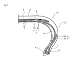
- Fig. 5 illustrates a half sectional view illustrating still another example of a pneumatic tire of the present invention in the width direction.
- the illustrated pneumatic tire 40 is a run flat tire having the same constitution as the pneumatic tire 30 illustrated in Fig. 4 , except that the tire comprises a pair of side-reinforcing rubber layers 6 having a crescent-shaped meridional cross section all or almost all over the both side wall portions 12 along the inner surface of the carcass 2.
- a cap ply covering the whole width of the belt layer is disposed as the belt reinforcing layer 4, while in the present invention, the disposition of the belt reinforcing layer 4 is not indispensable.
- a layer ply covering on both the end portions of the belt layer may be disposed as the belt reinforcing layer 4.
- the belt reinforcing layer 4 may be constituted only by a layer ply, and the number of respective plies is not particularly restricted.
- the cap ply and the layer ply are individually composed of rubberized reinforcing cord layer which is substantially disposed in the tire circumferential direction.
- the belt layer is usually composed of a rubber layer having cords which extend obliquely with respect to the tire equatorial plane, and preferably, composed of at least one layer of rubberized steel cord layer.
- two belt layers are piled such that the cords which constitute the belt layer intersect each other to constitute a belt layer 3.
- a bead filler 7 disposed on the outer side of the bead core 1 in the tire radial direction has a triangle shaped cross section having a height of 15 mm or smaller, particularly, 10 mm or smaller.
- a compression input repeatedly applied by an input of a product is applied to a carcass cord, decrease in the strength ofthe carcass cord of the turn-up portion is accelerated and the tire may break due to carcass cord breakage.
- the carcass cord is expected that the strength is hard to decrease due to compression input, in other word, the carcass cord is expected to have a good fatigue performance.
- the turn-up portion of the carcass cord is just along the inner side of the tire.
- the carcass cord therefore exists on the outer side of the flexural deformation when a flexural input using as a fulcrum point a contact point between the rim flange and the tire is applied to the vicinity of the bead portion when a load is applied, and as the result, not compression input but only a tension input is applied to the cord.
- the height of the bead filler 7 means the height of the bead filler 7 in the radial direction in a condition in which a load is not applied when the tire is assembled on an application rim and is inflated to a standard air pressure.
- the application rim refers to a rim defined in the following standard.
- the normal air pressure refers to an air pressure defined corresponding to the maximum load capacity in the standard below.
- the "standard" is an industrial standard effective in the region where the tire is manufactured or used.
- the standard is “Year Book” by The Tire and Rim Association Inc.; in Europe, the standard is “Standards Manual” by The European Tire and Rim Technical Organization; and in Japan, the standard is JATMA Year book by Japan Automobile Tyre Manufacturers Association.
- the height of the bead filler 7 is set to 15 mm or less because since the shape and the value of the rim flange are standardized, by setting the height of the bead filler 7 to 15 mm or less regardless of the size, the carcass cord can avoid a portion where a compression input is applied.
- a compression input may be applied to on the verge of the ply end due to the flexural rigidity around the bead, inner pressure conditions, input or the like. It is therefore suitable that, by setting the height of the bead filler 7 to 10 mm or smaller, compression input can surely be avoided regardless of the type of the tire.
- the lower limit of the height of the bead filler 7 is not particularly limited.
- the height can also be 0 mm (no bead filler rubber).
- both the condition relating to the height of the tum-up end portion of the above-mentioned carcass ply and the condition relating to the height of the bead filler are satisfied.
- the turn-up end portion of the carcass ply is turned up at least to the upper end position in the tire radial direction of the bead core, the height of the turn-up end portion of the carcass ply in the tire radial direction from the upper end portion of the bead core in the tire radial direction is 15 mm or smaller and a bead filler has a triangle shaped cross section having a height of 15 mm or smaller.
- a high rigidity cellulose fiber cord to a carcass cord and the specific carcass disposition is important, by which a desired effect of the present invention can be obtained.
- the structure or material of the other members which constitutes a tire should not be particularly limited, know structure and material can be employed.
- a tread pattern (not illustrated) is formed as appropriate, and on the innermost layer, an inner liner (not illustrated) is formed.
- an inert gas such as nitrogen can be used as a gas with which the tire to be filled.
- a tire of a type as illustrated in Fig. 1 (size 245/45R19) was manufactured. Shown in Tables 1 and 2 below are the material, the structure, the twist coefficient of the reinforcing cord of the carcass ply, and the cord modulus of elasticity of the reinforcing cord of the carcass ply under a stress under which a force of 29.4 N per reinforcing cord was applied to at a temperature of 80°C.
- a dip liquid having a molar ratio of formaldehyde/resorcinol of 1.98, resorcinol ⁇ formaldehyde /latex solid % by mass of 16.0 and a molar ratio of (NaOH + NH 4 OH) /latex of 0.80 was used.
- a covering rubber comprising 100 parts by mass of natural rubber, 50 parts by mass of HAF carbon black and 3 parts by mass of sulfur was used. The end count of the carcass ply into the tire was 70/10 cm.
- the modulus of elasticity of the reinforcing cord at 180°C was, as mentioned above, calculated by using the stress-elongation curve of the cord, estimating the force applied to one cord at the time when a tire was inflated to the inner pressure to the time when load was applied to a tire as 29.4 N and drawing a tangent line on the stress-elongation curve under a stress of 29.4 N (see Fig. 2 ).
- a durability drum running test was carried out with a drum tester in which the surface of the drum was smooth, which was made of steel and in which the diameter ofthe drum was 1.707 m, by controlling the ambient temperature to 30 ⁇ 3°C, using a rim having a standard rim size defined by JATMA and applying a standard load capacity according to JATMA standard at a standard inner pressure according to JATMA standard, to measure the distance until the tire was broke.
- the evaluations were indicated in Tables 1 and 2 as indices taking the case of Comparative Example 1 as 100. The larger the value of the index, the more favorable the durability.
- a test tire employing a rim having a standard rim size defined by JATMA and inflated to a standard inner pressure according to a JATMA standard was mounted on a real car, a drivability feeling test was carried out by a driver and the driving stability was scored from 0 to 100.
- the obtained results are indicated in Tables 1 and 2.
- Pneumatic radial tires of Examples and Comparative Examples of a tire size 215/45R17 were manufactured by applying as the carcass cord an organic fiber cord satisfying the conditions indicated in the Table below and by changing the height ofthe bead filer of the triangle shaped cross section as indicated in the Table below.
- the number of carcass ply used was one, and the carcass cord was turned up around the bead core from the inside of the tire to the outside of the tire.
- Two belt layers were used and the belt layer was composed of rubberized steel cord layer extending obliquely at an angle of ⁇ 30° with respect to the tire equatorial plane.
- the formulation of the dip liquid, the formulation of covering rubber of a carcass ply, the end count of the carcass ply and the method of calculating the tensile modulus of elasticity were the same as in the above mentioned Example 1.
- the durability and the drivability were evaluated according to the following.
- a test tire was mounted on a real car, a drivability feeling test was carried out by a driver and the drivability was scored from 0 to 100. The higher the score, the more favorable the drivability.
Landscapes
- Engineering & Computer Science (AREA)
- Mechanical Engineering (AREA)
- Tires In General (AREA)
Applications Claiming Priority (3)
| Application Number | Priority Date | Filing Date | Title |
|---|---|---|---|
| JP2010093715A JP5512369B2 (ja) | 2010-04-15 | 2010-04-15 | 空気入りタイヤ |
| JP2010203721A JP2012056519A (ja) | 2010-09-10 | 2010-09-10 | 空気入りラジアルタイヤ |
| PCT/JP2011/059425 WO2011129444A1 (ja) | 2010-04-15 | 2011-04-15 | 空気入りタイヤ |
Publications (3)
| Publication Number | Publication Date |
|---|---|
| EP2559570A1 true EP2559570A1 (de) | 2013-02-20 |
| EP2559570A4 EP2559570A4 (de) | 2015-04-15 |
| EP2559570B1 EP2559570B1 (de) | 2017-03-08 |
Family
ID=44798812
Family Applications (1)
| Application Number | Title | Priority Date | Filing Date |
|---|---|---|---|
| EP11768965.3A Not-in-force EP2559570B1 (de) | 2010-04-15 | 2011-04-15 | Luftreifen |
Country Status (4)
| Country | Link |
|---|---|
| US (1) | US20130025761A1 (de) |
| EP (1) | EP2559570B1 (de) |
| CN (1) | CN102858556B (de) |
| WO (1) | WO2011129444A1 (de) |
Families Citing this family (9)
| Publication number | Priority date | Publication date | Assignee | Title |
|---|---|---|---|---|
| JP6028359B2 (ja) * | 2012-03-23 | 2016-11-16 | 横浜ゴム株式会社 | 空気入りタイヤ |
| JP5973772B2 (ja) * | 2012-04-19 | 2016-08-23 | 株式会社ブリヂストン | ランフラットタイヤ |
| JP5868303B2 (ja) * | 2012-10-16 | 2016-02-24 | 横浜ゴム株式会社 | 空気入りタイヤ |
| WO2014126701A1 (en) * | 2013-02-15 | 2014-08-21 | Bridgestone Americas Tire Operations, Llc | Tire having an asymmetric body ply construction |
| JP6092058B2 (ja) * | 2013-09-13 | 2017-03-08 | 東洋ゴム工業株式会社 | 空気入りラジアルタイヤ |
| JP7047703B2 (ja) * | 2018-10-26 | 2022-04-05 | 横浜ゴム株式会社 | 空気入りタイヤ |
| JP7107255B2 (ja) * | 2019-03-07 | 2022-07-27 | 横浜ゴム株式会社 | 空気入りタイヤ |
| JP7028225B2 (ja) * | 2019-08-29 | 2022-03-02 | 横浜ゴム株式会社 | 空気入りタイヤ |
| JP7353902B2 (ja) * | 2019-10-04 | 2023-10-02 | 株式会社ブリヂストン | 空気入りタイヤ |
Family Cites Families (16)
| Publication number | Priority date | Publication date | Assignee | Title |
|---|---|---|---|---|
| JPS6028848A (ja) | 1983-07-26 | 1985-02-14 | Soichi Yamaguchi | ナトム工法における粉じん防止用噴霧装置 |
| JPS638007A (ja) * | 1986-06-24 | 1988-01-13 | ザ グツドイア− タイヤ アンド ラバ− コンパニ− | 空気入りタイヤ |
| JPH0253613A (ja) * | 1988-08-11 | 1990-02-22 | Sumitomo Rubber Ind Ltd | タイヤ |
| JP2913322B2 (ja) * | 1989-09-08 | 1999-06-28 | 横浜ゴム株式会社 | ランフラット空気入りラジアルタイヤ |
| JP3229381B2 (ja) * | 1992-08-27 | 2001-11-19 | 横浜ゴム株式会社 | 空気入りラジアルタイヤ |
| JP3247512B2 (ja) | 1993-09-13 | 2002-01-15 | 株式会社ブリヂストン | 空気入りラジアルタイヤ |
| AT404032B (de) | 1996-03-04 | 1998-07-27 | Chemiefaser Lenzing Ag | Verfahren zur herstellung cellulosischer fasern |
| US6230773B1 (en) * | 1998-03-17 | 2001-05-15 | The Goodyear Tire & Rubber Company | Tire with sidewall carcass reinforcement |
| KR100385400B1 (ko) * | 2001-04-11 | 2003-05-23 | 주식회사 효성 | 승용차용 래디얼 타이어 |
| CA2438445C (en) * | 2002-12-26 | 2006-11-28 | Hyosung Corporation | Lyocell multi-filament for tire cord and method of producing the same |
| JP4450633B2 (ja) | 2004-01-13 | 2010-04-14 | 株式会社ブリヂストン | 空気入りタイヤ |
| JP2006076431A (ja) * | 2004-09-09 | 2006-03-23 | Toyo Tire & Rubber Co Ltd | ランフラットタイヤ |
| JP2009001073A (ja) * | 2007-06-19 | 2009-01-08 | Yokohama Rubber Co Ltd:The | 空気入りラジアルタイヤ |
| JP4933990B2 (ja) * | 2007-09-03 | 2012-05-16 | 住友ゴム工業株式会社 | 自動二輪車用タイヤ |
| JP2010042762A (ja) * | 2008-08-13 | 2010-02-25 | Bridgestone Corp | 空気入りタイヤ |
| JP2010070119A (ja) * | 2008-09-19 | 2010-04-02 | Bridgestone Corp | 空気入りタイヤ |
-
2011
- 2011-04-15 WO PCT/JP2011/059425 patent/WO2011129444A1/ja not_active Ceased
- 2011-04-15 EP EP11768965.3A patent/EP2559570B1/de not_active Not-in-force
- 2011-04-15 CN CN201180018868.9A patent/CN102858556B/zh not_active Expired - Fee Related
- 2011-04-15 US US13/640,983 patent/US20130025761A1/en not_active Abandoned
Also Published As
| Publication number | Publication date |
|---|---|
| WO2011129444A1 (ja) | 2011-10-20 |
| EP2559570A4 (de) | 2015-04-15 |
| CN102858556A (zh) | 2013-01-02 |
| US20130025761A1 (en) | 2013-01-31 |
| CN102858556B (zh) | 2016-06-22 |
| EP2559570B1 (de) | 2017-03-08 |
Similar Documents
| Publication | Publication Date | Title |
|---|---|---|
| EP2559570B1 (de) | Luftreifen | |
| US9168788B2 (en) | Pneumatic tire | |
| JP5123587B2 (ja) | ランフラットタイヤ | |
| EP3130482A1 (de) | Radialluftreifen zur verwendung an einem passagierfahrzeug | |
| EP3130479A1 (de) | Radialluftreifen zur verwendung an einem passagierfahrzeug | |
| EP1867497A1 (de) | Run-flat-reifen | |
| US20130340907A1 (en) | Tire with a segmented overlay layer | |
| CN102574424B (zh) | 缺气保用轮胎 | |
| JP5180562B2 (ja) | ランフラットタイヤ | |
| US20200016941A1 (en) | Pneumatic tire | |
| JP2009137449A (ja) | ランフラットタイヤ | |
| CN107031294A (zh) | 充气轮胎 | |
| JP7587159B2 (ja) | タイヤ | |
| EP3153331A1 (de) | Luftreifen | |
| EP3549787A1 (de) | Gummi-kord-verbundstoff, verstärkungselement für reifen und reifen damit | |
| JP5185599B2 (ja) | ランフラットタイヤ | |
| JP4849983B2 (ja) | ランフラットタイヤ | |
| US20230241922A1 (en) | Pneumatic tire | |
| JP2009120024A (ja) | ランフラットタイヤ | |
| JP2009126347A (ja) | ランフラットタイヤ | |
| US20220274445A1 (en) | Pneumatic tire | |
| JP5512369B2 (ja) | 空気入りタイヤ | |
| JP5465587B2 (ja) | ランフラットタイヤ | |
| US20210370721A1 (en) | Pneumatic tire | |
| JP2009090776A (ja) | ランフラットタイヤ |
Legal Events
| Date | Code | Title | Description |
|---|---|---|---|
| PUAI | Public reference made under article 153(3) epc to a published international application that has entered the european phase |
Free format text: ORIGINAL CODE: 0009012 |
|
| 17P | Request for examination filed |
Effective date: 20121019 |
|
| AK | Designated contracting states |
Kind code of ref document: A1 Designated state(s): AL AT BE BG CH CY CZ DE DK EE ES FI FR GB GR HR HU IE IS IT LI LT LU LV MC MK MT NL NO PL PT RO RS SE SI SK SM TR |
|
| DAX | Request for extension of the european patent (deleted) | ||
| RA4 | Supplementary search report drawn up and despatched (corrected) |
Effective date: 20150316 |
|
| RIC1 | Information provided on ipc code assigned before grant |
Ipc: B60C 9/00 20060101ALI20150310BHEP Ipc: B60C 9/20 20060101ALI20150310BHEP Ipc: B60C 9/08 20060101AFI20150310BHEP Ipc: B60C 17/00 20060101ALI20150310BHEP |
|
| GRAP | Despatch of communication of intention to grant a patent |
Free format text: ORIGINAL CODE: EPIDOSNIGR1 |
|
| INTG | Intention to grant announced |
Effective date: 20160919 |
|
| GRAS | Grant fee paid |
Free format text: ORIGINAL CODE: EPIDOSNIGR3 |
|
| GRAA | (expected) grant |
Free format text: ORIGINAL CODE: 0009210 |
|
| AK | Designated contracting states |
Kind code of ref document: B1 Designated state(s): AL AT BE BG CH CY CZ DE DK EE ES FI FR GB GR HR HU IE IS IT LI LT LU LV MC MK MT NL NO PL PT RO RS SE SI SK SM TR |
|
| REG | Reference to a national code |
Ref country code: GB Ref legal event code: FG4D |
|
| REG | Reference to a national code |
Ref country code: CH Ref legal event code: EP Ref country code: AT Ref legal event code: REF Ref document number: 873185 Country of ref document: AT Kind code of ref document: T Effective date: 20170315 |
|
| REG | Reference to a national code |
Ref country code: IE Ref legal event code: FG4D |
|
| REG | Reference to a national code |
Ref country code: FR Ref legal event code: PLFP Year of fee payment: 7 |
|
| REG | Reference to a national code |
Ref country code: DE Ref legal event code: R096 Ref document number: 602011035741 Country of ref document: DE |
|
| REG | Reference to a national code |
Ref country code: LT Ref legal event code: MG4D |
|
| REG | Reference to a national code |
Ref country code: NL Ref legal event code: MP Effective date: 20170308 |
|
| PG25 | Lapsed in a contracting state [announced via postgrant information from national office to epo] |
Ref country code: HR Free format text: LAPSE BECAUSE OF FAILURE TO SUBMIT A TRANSLATION OF THE DESCRIPTION OR TO PAY THE FEE WITHIN THE PRESCRIBED TIME-LIMIT Effective date: 20170308 Ref country code: NO Free format text: LAPSE BECAUSE OF FAILURE TO SUBMIT A TRANSLATION OF THE DESCRIPTION OR TO PAY THE FEE WITHIN THE PRESCRIBED TIME-LIMIT Effective date: 20170608 Ref country code: LT Free format text: LAPSE BECAUSE OF FAILURE TO SUBMIT A TRANSLATION OF THE DESCRIPTION OR TO PAY THE FEE WITHIN THE PRESCRIBED TIME-LIMIT Effective date: 20170308 Ref country code: GR Free format text: LAPSE BECAUSE OF FAILURE TO SUBMIT A TRANSLATION OF THE DESCRIPTION OR TO PAY THE FEE WITHIN THE PRESCRIBED TIME-LIMIT Effective date: 20170609 Ref country code: FI Free format text: LAPSE BECAUSE OF FAILURE TO SUBMIT A TRANSLATION OF THE DESCRIPTION OR TO PAY THE FEE WITHIN THE PRESCRIBED TIME-LIMIT Effective date: 20170308 |
|
| REG | Reference to a national code |
Ref country code: AT Ref legal event code: MK05 Ref document number: 873185 Country of ref document: AT Kind code of ref document: T Effective date: 20170308 |
|
| PG25 | Lapsed in a contracting state [announced via postgrant information from national office to epo] |
Ref country code: BG Free format text: LAPSE BECAUSE OF FAILURE TO SUBMIT A TRANSLATION OF THE DESCRIPTION OR TO PAY THE FEE WITHIN THE PRESCRIBED TIME-LIMIT Effective date: 20170608 Ref country code: RS Free format text: LAPSE BECAUSE OF FAILURE TO SUBMIT A TRANSLATION OF THE DESCRIPTION OR TO PAY THE FEE WITHIN THE PRESCRIBED TIME-LIMIT Effective date: 20170308 Ref country code: ES Free format text: LAPSE BECAUSE OF FAILURE TO SUBMIT A TRANSLATION OF THE DESCRIPTION OR TO PAY THE FEE WITHIN THE PRESCRIBED TIME-LIMIT Effective date: 20170308 Ref country code: LV Free format text: LAPSE BECAUSE OF FAILURE TO SUBMIT A TRANSLATION OF THE DESCRIPTION OR TO PAY THE FEE WITHIN THE PRESCRIBED TIME-LIMIT Effective date: 20170308 Ref country code: SE Free format text: LAPSE BECAUSE OF FAILURE TO SUBMIT A TRANSLATION OF THE DESCRIPTION OR TO PAY THE FEE WITHIN THE PRESCRIBED TIME-LIMIT Effective date: 20170308 |
|
| PG25 | Lapsed in a contracting state [announced via postgrant information from national office to epo] |
Ref country code: NL Free format text: LAPSE BECAUSE OF FAILURE TO SUBMIT A TRANSLATION OF THE DESCRIPTION OR TO PAY THE FEE WITHIN THE PRESCRIBED TIME-LIMIT Effective date: 20170308 |
|
| PG25 | Lapsed in a contracting state [announced via postgrant information from national office to epo] |
Ref country code: RO Free format text: LAPSE BECAUSE OF FAILURE TO SUBMIT A TRANSLATION OF THE DESCRIPTION OR TO PAY THE FEE WITHIN THE PRESCRIBED TIME-LIMIT Effective date: 20170308 Ref country code: EE Free format text: LAPSE BECAUSE OF FAILURE TO SUBMIT A TRANSLATION OF THE DESCRIPTION OR TO PAY THE FEE WITHIN THE PRESCRIBED TIME-LIMIT Effective date: 20170308 Ref country code: AT Free format text: LAPSE BECAUSE OF FAILURE TO SUBMIT A TRANSLATION OF THE DESCRIPTION OR TO PAY THE FEE WITHIN THE PRESCRIBED TIME-LIMIT Effective date: 20170308 Ref country code: SK Free format text: LAPSE BECAUSE OF FAILURE TO SUBMIT A TRANSLATION OF THE DESCRIPTION OR TO PAY THE FEE WITHIN THE PRESCRIBED TIME-LIMIT Effective date: 20170308 Ref country code: CZ Free format text: LAPSE BECAUSE OF FAILURE TO SUBMIT A TRANSLATION OF THE DESCRIPTION OR TO PAY THE FEE WITHIN THE PRESCRIBED TIME-LIMIT Effective date: 20170308 |
|
| PG25 | Lapsed in a contracting state [announced via postgrant information from national office to epo] |
Ref country code: IS Free format text: LAPSE BECAUSE OF FAILURE TO SUBMIT A TRANSLATION OF THE DESCRIPTION OR TO PAY THE FEE WITHIN THE PRESCRIBED TIME-LIMIT Effective date: 20170708 Ref country code: PL Free format text: LAPSE BECAUSE OF FAILURE TO SUBMIT A TRANSLATION OF THE DESCRIPTION OR TO PAY THE FEE WITHIN THE PRESCRIBED TIME-LIMIT Effective date: 20170308 Ref country code: SM Free format text: LAPSE BECAUSE OF FAILURE TO SUBMIT A TRANSLATION OF THE DESCRIPTION OR TO PAY THE FEE WITHIN THE PRESCRIBED TIME-LIMIT Effective date: 20170308 Ref country code: PT Free format text: LAPSE BECAUSE OF FAILURE TO SUBMIT A TRANSLATION OF THE DESCRIPTION OR TO PAY THE FEE WITHIN THE PRESCRIBED TIME-LIMIT Effective date: 20170710 |
|
| REG | Reference to a national code |
Ref country code: CH Ref legal event code: PL |
|
| REG | Reference to a national code |
Ref country code: DE Ref legal event code: R097 Ref document number: 602011035741 Country of ref document: DE |
|
| PLBE | No opposition filed within time limit |
Free format text: ORIGINAL CODE: 0009261 |
|
| STAA | Information on the status of an ep patent application or granted ep patent |
Free format text: STATUS: NO OPPOSITION FILED WITHIN TIME LIMIT |
|
| REG | Reference to a national code |
Ref country code: IE Ref legal event code: MM4A |
|
| PG25 | Lapsed in a contracting state [announced via postgrant information from national office to epo] |
Ref country code: DK Free format text: LAPSE BECAUSE OF FAILURE TO SUBMIT A TRANSLATION OF THE DESCRIPTION OR TO PAY THE FEE WITHIN THE PRESCRIBED TIME-LIMIT Effective date: 20170308 Ref country code: MC Free format text: LAPSE BECAUSE OF FAILURE TO SUBMIT A TRANSLATION OF THE DESCRIPTION OR TO PAY THE FEE WITHIN THE PRESCRIBED TIME-LIMIT Effective date: 20170308 |
|
| 26N | No opposition filed |
Effective date: 20171211 |
|
| GBPC | Gb: european patent ceased through non-payment of renewal fee |
Effective date: 20170608 |
|
| PG25 | Lapsed in a contracting state [announced via postgrant information from national office to epo] |
Ref country code: CH Free format text: LAPSE BECAUSE OF NON-PAYMENT OF DUE FEES Effective date: 20170430 Ref country code: SI Free format text: LAPSE BECAUSE OF FAILURE TO SUBMIT A TRANSLATION OF THE DESCRIPTION OR TO PAY THE FEE WITHIN THE PRESCRIBED TIME-LIMIT Effective date: 20170308 Ref country code: LU Free format text: LAPSE BECAUSE OF NON-PAYMENT OF DUE FEES Effective date: 20170415 Ref country code: LI Free format text: LAPSE BECAUSE OF NON-PAYMENT OF DUE FEES Effective date: 20170430 |
|
| REG | Reference to a national code |
Ref country code: BE Ref legal event code: MM Effective date: 20170430 |
|
| REG | Reference to a national code |
Ref country code: FR Ref legal event code: PLFP Year of fee payment: 8 |
|
| PG25 | Lapsed in a contracting state [announced via postgrant information from national office to epo] |
Ref country code: IE Free format text: LAPSE BECAUSE OF NON-PAYMENT OF DUE FEES Effective date: 20170415 Ref country code: GB Free format text: LAPSE BECAUSE OF NON-PAYMENT OF DUE FEES Effective date: 20170608 |
|
| PG25 | Lapsed in a contracting state [announced via postgrant information from national office to epo] |
Ref country code: BE Free format text: LAPSE BECAUSE OF NON-PAYMENT OF DUE FEES Effective date: 20170430 |
|
| PG25 | Lapsed in a contracting state [announced via postgrant information from national office to epo] |
Ref country code: MT Free format text: LAPSE BECAUSE OF NON-PAYMENT OF DUE FEES Effective date: 20170415 |
|
| PG25 | Lapsed in a contracting state [announced via postgrant information from national office to epo] |
Ref country code: HU Free format text: LAPSE BECAUSE OF FAILURE TO SUBMIT A TRANSLATION OF THE DESCRIPTION OR TO PAY THE FEE WITHIN THE PRESCRIBED TIME-LIMIT; INVALID AB INITIO Effective date: 20110415 |
|
| PG25 | Lapsed in a contracting state [announced via postgrant information from national office to epo] |
Ref country code: CY Free format text: LAPSE BECAUSE OF NON-PAYMENT OF DUE FEES Effective date: 20170308 |
|
| PG25 | Lapsed in a contracting state [announced via postgrant information from national office to epo] |
Ref country code: MK Free format text: LAPSE BECAUSE OF FAILURE TO SUBMIT A TRANSLATION OF THE DESCRIPTION OR TO PAY THE FEE WITHIN THE PRESCRIBED TIME-LIMIT Effective date: 20170308 |
|
| PG25 | Lapsed in a contracting state [announced via postgrant information from national office to epo] |
Ref country code: TR Free format text: LAPSE BECAUSE OF FAILURE TO SUBMIT A TRANSLATION OF THE DESCRIPTION OR TO PAY THE FEE WITHIN THE PRESCRIBED TIME-LIMIT Effective date: 20170308 |
|
| PG25 | Lapsed in a contracting state [announced via postgrant information from national office to epo] |
Ref country code: AL Free format text: LAPSE BECAUSE OF FAILURE TO SUBMIT A TRANSLATION OF THE DESCRIPTION OR TO PAY THE FEE WITHIN THE PRESCRIBED TIME-LIMIT Effective date: 20170308 |
|
| PGFP | Annual fee paid to national office [announced via postgrant information from national office to epo] |
Ref country code: DE Payment date: 20200420 Year of fee payment: 10 Ref country code: FR Payment date: 20200420 Year of fee payment: 10 |
|
| PGFP | Annual fee paid to national office [announced via postgrant information from national office to epo] |
Ref country code: IT Payment date: 20200428 Year of fee payment: 10 |
|
| REG | Reference to a national code |
Ref country code: DE Ref legal event code: R119 Ref document number: 602011035741 Country of ref document: DE |
|
| PG25 | Lapsed in a contracting state [announced via postgrant information from national office to epo] |
Ref country code: DE Free format text: LAPSE BECAUSE OF NON-PAYMENT OF DUE FEES Effective date: 20211103 Ref country code: FR Free format text: LAPSE BECAUSE OF NON-PAYMENT OF DUE FEES Effective date: 20210430 |
|
| PG25 | Lapsed in a contracting state [announced via postgrant information from national office to epo] |
Ref country code: IT Free format text: LAPSE BECAUSE OF NON-PAYMENT OF DUE FEES Effective date: 20200415 |
|
| PG25 | Lapsed in a contracting state [announced via postgrant information from national office to epo] |
Ref country code: IT Free format text: LAPSE BECAUSE OF NON-PAYMENT OF DUE FEES Effective date: 20210415 |