EP2559628A1 - Récipient empilable ainsi qu'agencement de récipients avec plusieurs récipients de ce type - Google Patents
Récipient empilable ainsi qu'agencement de récipients avec plusieurs récipients de ce type Download PDFInfo
- Publication number
- EP2559628A1 EP2559628A1 EP12003999A EP12003999A EP2559628A1 EP 2559628 A1 EP2559628 A1 EP 2559628A1 EP 12003999 A EP12003999 A EP 12003999A EP 12003999 A EP12003999 A EP 12003999A EP 2559628 A1 EP2559628 A1 EP 2559628A1
- Authority
- EP
- European Patent Office
- Prior art keywords
- container
- coupling element
- container body
- coupling
- wall
- Prior art date
- Legal status (The legal status is an assumption and is not a legal conclusion. Google has not performed a legal analysis and makes no representation as to the accuracy of the status listed.)
- Granted
Links
Images




Classifications
-
- B—PERFORMING OPERATIONS; TRANSPORTING
- B65—CONVEYING; PACKING; STORING; HANDLING THIN OR FILAMENTARY MATERIAL
- B65D—CONTAINERS FOR STORAGE OR TRANSPORT OF ARTICLES OR MATERIALS, e.g. BAGS, BARRELS, BOTTLES, BOXES, CANS, CARTONS, CRATES, DRUMS, JARS, TANKS, HOPPERS, FORWARDING CONTAINERS; ACCESSORIES, CLOSURES, OR FITTINGS THEREFOR; PACKAGING ELEMENTS; PACKAGES
- B65D21/00—Nestable, stackable or joinable containers; Containers of variable capacity
- B65D21/02—Containers specially shaped, or provided with fittings or attachments, to facilitate nesting, stacking, or joining together
- B65D21/0209—Containers specially shaped, or provided with fittings or attachments, to facilitate nesting, stacking, or joining together stackable or joined together one-upon-the-other in the upright or upside-down position
- B65D21/0213—Containers presenting a continuous stacking profile along the upper or lower edge of at least two opposite side walls
Definitions
- the invention relates to a stackable container, having a rectangular plan view, having a bottom wall in use position bottom wall and four starting from the bottom wall upwardly projecting, side by side opposite box-shaped container body, and with at least two coupling elements, each taking a Working position outside on one of two opposing side walls in the lower region are arranged or attachable to allow a vertically continuous coupling of the container with a further container placed underneath, each coupling element has a fixing portion with which it fixes in the working position on the container body is, and has a downwardly projecting, in spring-back manner in a release direction relative to the container body pivotable latch portion.
- the invention further relates to a container arrangement with a plurality of such stackable containers.
- a stackable container of this type as well as a composed of several such stackable containers container assembly go out of the WO 2007/121745 A1 out.
- the known stackable container has a box-shaped, upwardly open container body with opposite pairs Side walls, wherein in the lower region of two opposing side walls outside each provided with a Schnappriegelab bainites a coupling element is arranged.
- the latch portion protrudes downwardly and is pivotable in a releasing manner in a release direction to facilitate coupling and decoupling with a further container of the same type disposed below the container.
- a coupling element is rotatably mounted on a bearing shaft and biased by a separate spring.
- the other coupling element may consist of a resilient material.
- Each coupling element is fastened by means of a fastening portion on the container body of the container, wherein the fastening portion is rotatably mounted in one case on the bearing shaft and in the other case is integrally connected to the container body.
- Stackable containers with a box-shaped container body are often used in internal logistical measures, for example, to handle shipping orders or to supply individual workstations with work materials in manufacturing technology. Especially in the empty state, the containers are stacked so that they take up as little storage space as possible until they are used.
- the invention has for its object to provide measures to simplify the handling of stackable container at the same time cost-effective design.
- each coupling element is fixed in the working position with its attachment portion by a plug connection to the container body, that the attachment portion in a Mitverschwenken with the pivoted in the release direction snap latch portion preventing manner the container body is supported, wherein it is inherently resiliently designed such that its snap latch portion is pivotable relative to the fastening portion supported by the connector in the release direction.
- the container body of a stackable container depending on the application either with coupling elements to equip or not to stock. If the containers are to be stacked on each other without vertically connected coupling in an easily separable manner, the coupling elements remain unmounted and consequently do not occupy a working position fixed to a container body. In the context of applications, however, which involves vertically connected coupling of stacked containers make desirable, the coupling elements can be very easily fixed by the connector in its working position on the associated container body.
- the production of the connector is particularly simple because no separate spring means must be mounted to produce the resilient pivoting of the latch portion.
- the coupling elements are releasably secured in the working position on the container body.
- a stackable container can be converted at any time between a possibility of use with vertical coupling and a possibility of use without vertical coupling. If a coupling is not desired, the coupling elements can be removed from the working position, that is to say remove from the container body and keep it independent of the container body until it can be used again.
- An inserted into the receiving shaft mounting portion is suitably supported by the receiving shaft limiting shaft wall.
- a support is provided at right angles to the expansion plane of the associated side wall of the container body. In this way, the mounting portion undergoes the necessary support, which prevents it from comprehending the occurring in the release direction pivotal movement of the latch portion so that selbiger returns to its normal position when an effective force in the release direction is removed.
- the receiving shaft expediently has a partially open outer shaft wall on the outside facing away from the associated side wall of the container. Such an opening may be formed like a window. It is particularly expedient to reduce the outer shaft wall to only two mutually spaced, edge-side retaining strips, which are each preceded by an edge portion of the inserted attachment portion. Such an embodiment provides on the one hand for the desired support of the attachment portion and also offers the possibility to use the receiving shaft when not using a coupling element for receiving an information and / or identification badge.
- the receiving shaft has an inner shaft wall formed directly from the associated side wall of the container body, so that the receiving shaft can be realized very inexpensively.
- the inner and / or an outer shaft wall upstream of the inner shaft wall with respect to the height direction of the container inclined so that a measured transversely to the height direction of the container body distance between the inner shaft wall and the outer shaft wall with increasing shaft depth, ie with increasing distance to the insertion enlarged.
- Such a measure favors to provide the coupling element with a shape that contributes to a jamming of the mounting portion in the receiving shaft and / or to implement measures for an easily manageable latching fastening of the coupling element as needed.
- the coupling element which is switched on or engaged in the working position can be fixed by any securing measures with respect to the container body, so that it is held captive.
- the attachment portion can be fixed in the attached state frictionally. It can be pressed, for example, with bias in a receiving shaft.
- the container body is equipped with a receiving shaft in which the fixing portion of the fixed coupling element dips
- the fixing portion has on its the bottom surface of the receiving shaft end face facing at least a first locking means, which formed with a in the region of the bottom surface of the receiving shaft second locking means is in locking engagement or can be brought. It is advantageous in this case if the latching and possibly also possible unlatching can be accomplished by virtue of the fact that the fastening section in the interior of the receiving shaft can be pivoted relative to the container body when a corresponding actuating force is exerted on it.
- the coupling element is in particular designed such that the possible pivotal movement of the fastening section causing latching or unlatching can not be brought about by the spring-back pivoting of the snap-lock section.
- the fastening portion is virtually decoupled from the latching portion by the connector fixing it, due to the inherent resilience of the coupling member.
- a plate-shaped design is recommended. It is very easy to manufacture and ensures high rigidity. The same applies to the snap latch section.
- a particularly advantageous designed coupling element has a U-shaped configuration with two legs interconnected by a connecting web. One of these legs defines the attachment portion, the other leg the latch portion.
- the connecting web By the connecting web, the inherent spring elasticity of the coupling element can be ensured, which makes it possible to pivot the spring latch portion relative to the mounting portion resiliently spring-back.
- an embodiment of the coupling element in which the pivotal movement of the latch portion ensuring inherent spring elasticity is ensured by the structure of the latch portion at least significantly himself.
- the leg forming the snap-lock portion is expediently longer than the leg forming the fastening portion, so that the fastening portion is surmounted by the snap-lock portion.
- the projecting beyond the attachment portion end portion of the latch portion expediently carries a suitable for positive coupling with a further container below disposed locking projection, said locking projection is in particular oriented so that it faces the container body or projects to the fixed to the opposite side wall coupling element. Accordingly, the loosening direction of the latch portion is directed outward from the container body. This facilitates decoupling, since it is very easy to grasp both coupling elements, each with one hand, at its snap-lock section and to bend or pivot resiliently outwardly.
- the container body in the region of its bottom wall opposite top at least on the equipped with a coupling element or equippable side walls on such a coupling portion that he from Schnappriegelab steel of the coupling element on this container sitting similar stackable container for vertically connected coupling is under attack.
- the coupling portion is formed in particular by a transverse to the height direction of the container body outwardly projecting edge portion of the respective side wall, said edge portion may be designed in particular rib-shaped.
- a plurality of containers can be stacked in such a way that the respective top-sitting container with the underside of its support rib on the overhead support surface of the underlying container is supported and simultaneously with the bottom wall having lower end portion of the side walls from above a piece wide in dips the container interior of the lower container.
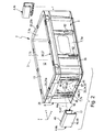
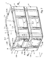
- illustrated container assembly 1 is composed of a plurality of stackable containers 2 shown in the stacked state, which are of the same type among each other, wherein the FIGS. 1 to 6 illustrate a single of these stackable container 2 and its components.
- the container arrangement 1 consists of two containers 2, the number, however, being arbitrary in principle.
- All containers 2 are expediently identical to each other. This favors stacking in any order.
- Each container 2 has a plurality of coupling elements 4, by means of which it can be coupled vertically contiguous in the stacked state of a container arrangement 1 as an upper container 2a with the lower container 2b arranged underneath.
- the containers 2 a, 2 b coupled in this way are connected in such a way that they can no longer be lifted apart from one another in the z-axis direction or height direction 3. It is then based on a positive connection tensile connection in the height direction 3 before.
- the container 2 has a box-shaped container body 5. More specifically, this container body 5, which has the already mentioned rectangular plan, wherein he expediently in the x-axis direction has a greater length than in the y-axis direction. However, a square layout would also be possible.
- the container 2 could include a container lid associated with the container opening 13 to close the container interior 12 in a manner accessible when needed.
- a container lid is not shown in the drawing.
- each container 2 can be optionally equipped with the coupling elements 4 or in this regard is empty. If the container body 5 is equipped with a coupling element 4, this assumes a working position on the container body 5. This is evident in the FIG. 1 as well as in the upper containers 2a of FIGS. 7 to 10 ,
- FIG. 2 illustrated container 2 and in the lower containers 2b of FIGS. 7 to 10 the container body 5 is not equipped with coupling elements 4, because he is currently not intended to be coupled to a further container 2 disposed thereunder.
- FIG. 2 illustrated by means of dash-dotted arrows 14a, 14b, as a coupling element 4 can be mounted on a hitherto still unpopulated container body 5.
- Each coupling element 4 has a fastening section 15 and a snap-lock section 16.
- the latch portion 16 carries at least one transversely projecting locking projection 17.
- the container 2 per coupling element 4 to be fixed is equipped with a plug-in connection device 18, to which the attachment section 15 and a counterpart section formed on the container body 5-exemplarily a receiving shaft 38 to be explained-belong.
- the coupling element 4 by means of a in FIG. 2 Arranged by arrow 22 plugging operation on the associated side wall 7a or 7b mounted and secured.
- the at least one locking projection 17 is arranged on the inner surface 24 of the snap latch section 16 facing the occupant position of the adjacent side wall 7 and thus protrudes in the direction of the coupling element 4 mounted on the opposite side wall 7.
- the container body 5 has a coupling section 25 in each case, with the first side wall 7a for better differentiation disposed coupling portion 25 as the first coupling portion 25a and arranged on the second side wall 7b coupling portion 25 is referred to as the second coupling portion 25b.
- the first coupling section 25a lies in the z-axis direction over the first coupling element 4a
- the second coupling section 25b lies in the z-axis direction above the first coupling element 4b.
- the coupling of two containers 2 expediently does not require immediate application of hands to the coupling elements 4. It suffices for this purpose to set up the upper container 2a in the direction of the arrow 27 coinciding with the z-axis direction from above onto the lower container 2b and press it with a certain force. In this case, then slide the locking projections 17 with a downwardly oriented inclined surface 28 on the outer edge of the coupling portions 25a, 25b and are pushed away from the associated side wall 7a, 7b, which is directed away from the adjacent side wall 7a, 7b pivoting the entire snap lock portion 16 in a through an arrow illustrated solving direction 32 results.
- the attachment portion is at least so supported relative to the container body 5, that he can not participate in the release direction 32 occurring pivotal movement of the latch portion 16, which has the described structure of the restoring spring force result.
- a spring bias of the deflected latch portion 16 in the direction of its normal position without the use of a separate, in addition to the coupling element 4 existing spring means.
- the connector device 18 is particularly designed so that a befindliches in the working position coupling element 4 can be removed again from the container body 5, if necessary, without having to make any destruction or damage. This provides the ability to retrofit a container 2 at any time.
- the securing means 33 may consist in a pertinent embodiment of the plug connection device 18 such that the coupling elements 4 are inserted with their attachment sections 15 in a press fit into the container body 5.
- the securing means 33 is present in the embodiment, where they are designed in the form of a latching connection device 34.
- This locking connection device 34 is expediently designed so that it allows a detachable latching connection between the coupling element 4 and the container body 5.
- the container body 5 has in the lower region of its peripheral wall 8 formed by the side walls 7 on the outer surface facing away from the container interior 12 with a height distance in the z-axis direction to the bottom wall 6 and extending like a frame around the peripheral wall 8 around supporting rib 35. It is preferably designed band-shaped.
- the upwardly facing, facing away from the bottom wall 6 upper end face 36 of the peripheral wall 8 and the side walls 7 an upwardly facing, the container opening 13 expediently surrounding framing support surface 37.
- the support surface 37 of the upwardly facing surface of the end rib 26 formed.
- the peripheral wall 8 projects downward beyond the support rib 35.
- the outer cross section of the container body 5 is below the support rib 35 is smaller than the inner cross section of the container interior 12 in the region of the container opening 13.
- This configuration is exemplary very simply realized in that the four side walls 7, starting from the bottom wall 6 diverge in the direction of the container opening 13 and slightly diverge diagonally. Seen in cross-section, this results in a conical configuration of each side wall pair forming side walls 7a, 7b and 7c, 7d.
- the distance of the support surface 37 to the vertical axis 3 is expediently the same as the correspondingly measured distance of the support rib 35 to the vertical axis 3.
- the support surface 37 and the support rib 35 have the same outline. When viewed in the z-axis direction, the support surface 37 and the support rib 35 overlap.
- the connector device 18 is exemplarily designed so that it allows a plug connection in the manner of a push-in connection.
- Each coupling element 4 can be inserted or pushed in with its fastening section 15 into a receptacle of the container body 5 provided for this purpose.
- a receiving shaft 38 for plug-in receptacle of the attachment portion 15 of a coupling element 4 is formed on the outside of each of the first and second side walls 7a, 7b.
- the receiving shaft 38 is above the support rib 35 and has on its upper side an upwardly facing, in particular slit-like narrow insertion opening 42.
- the receiving shaft 38 has an inner shaft wall 43, which is expediently formed directly from the associated first or second side wall 7a, 7b, and an outer shaft wall 44, which is externally disposed at a certain distance from the outer shaft wall 44 on the outside.
- the receiving shaft 38 at its insertion opening 42 opposite bottom on a bottom surface 45, by which it is limited to the bottom.
- This bottom surface 45 of the receiving shaft 38 is expediently formed directly by the support rib 35. Accordingly, the receiving shaft 38 preferably connects at the top directly to the on the associated side wall 7a, 7b formed portion of the support rib 35.
- the outer shaft wall 44 may be completely closed. As an example, however, it is partially open and is limited to two spaced-apart edge-side strip-shaped sections, which are referred to as retaining strips 46. Between the two retaining strips 46 there is a window-like opening opening into the receiving shaft 38, the advantage of which lies in the fact that an information and / or identification label inserted at the removed coupling element 4 into the receiving shaft 38 is easily recognizable from the outside.
- the outer shaft wall 44 expediently extends in a plane inclined to the vertical axis 3.
- the inner shaft wall 43 has due to the inclination of the associated side wall 7 also has an inclined course, but with respect to the outer shaft wall 44 opposite direction of inclination - with respect to the vertical axis 3 -, so that measured transversely to the height direction 3 distance between the inner shaft wall 43 and the outer shaft wall 44, starting from the insertion opening 42 in the direction of the bottom surface 45 increases.
- each coupling element 4 has expediently a U-shaped form, in particular from FIGS. 2 to 6 is clearly visible.
- each coupling element 4 has a first leg 47 forming the fastening section 15 and a second leg 48 forming the snap-lock section 16.
- the two legs 47, 48 are integrally connected to one another by a preferably web-shaped connecting web 49.
- At least one stiffening web 52 can be integrally formed on the connecting web 49 within the U opening, which is also integrally formed on the end regions of the first and second legs 47, 48 adjoining the connecting web 49.
- the second leg 48 forming the latch portion 16 expediently has-in the direction towards its free end remote from the connecting web 49 -a greater length than the first leg 47 forming the fastening portion 15, so that it opposes that first leg 47 at the connecting web 49 Side surmounted.
- the end section of the second leg 48 projecting beyond the first leg 47 has the locking projection 17, specifically on the inner surface 24 facing the first leg 47 and in particular on its end region.
- the locking projection 17 is designed in particular hook-shaped.
- each coupling element 4 is preferably a one-piece body, which consists of a plastic material having the necessary spring elasticity.
- a coupling element 4 In order to assemble a coupling element 4 in the working position, it is brought into abutment with downwardly projecting latch portion 16 and with the associated side wall 7 facing attachment portion 15 according to arrow 14a above the insertion opening 42 of the receiving shaft 38 on the side wall 7. Starting from this position, the coupling element 4 is linearly displaced in the Z-axis direction according to arrow 14b, so that the preferably plate-shaped fastening portion 15 is inserted or inserted through the insertion opening 42 into the receiving shaft 38.
- the insertion depth is preferably limited by the fact that the attachment portion 15 is seated with its end face 53 opposite the connecting web 49 on the bottom surface 45 of the receiving shaft 38.
- the two shaft walls 43, 44 jointly define an abutment for the fastening section 15, so that the latter is prevented from comprehending the pivot movement of the snap-lock section 16.
- the already mentioned resetting spring force can be formed.
- the receiving shaft 38 is bounded by a respective lateral shaft wall 54, which is formed in particular by each one of the outside of the side wall 7 in the Z-axis direction extending stiffening rib 59.
- the preferably present locking connection means 34 includes in the embodiment a arranged on the bottom surface 45 of the receiving shaft 38 second locking means 55, which is formed by the outer edge of the support rib 35 passing through opening 57.
- the latching connection device 34 has a first latching means 56 which is arranged on the free end face 53 of the fastening section 15 and which is designed as a latching hook.
- the two legs 47, 48 of the coupling element 4 are preferably designed such that they approach each other towards their free ends. The distance between them thus decreases towards their free ends.
- the mounting portion 15 when the mounting portion 15 is inserted into the receiving shaft 38 during assembly of a coupling element 4, it moves in an oblique orientation in the direction the bottom surface 45 until the first locking means 56 comes from above at the edge of the opening 57 to the plant. Due to a frontal slight bevel of the first latching means 56 experiences this, when the mounting portion 15 is further pressed in its insertion 14 b in the receiving shaft 38, a temporary resilient deflection in the direction of the inner shaft wall 43 until the first locking means 56 has passed through the opening 57 and then swung back again, so that it engages under the second locking means 55 formed by the edge of the opening 57. Now the locking connection is made.
- the distance to the bottom surface 45 towards increasing distance between the inner shaft wall 43 and the outer shaft wall 44 ensures the mentioned pivoting mobility, which is required to carry out the latching operation.
- an actuating force pivoting the first latching means 56 in the direction of the inner shaft wall 43 can be exerted manually or with a tool from the underside of the support rib 35 so that the first latching means 56 is aligned with the opening 57 and the coupling element 4 can be pushed out of the receiving shaft 38 in this position in opposite direction with respect to the arrow 14a or pulled out.
- the mounting portion 15 is provided sufficient freedom of movement available to allow a desired latching and unlatching relative pivotal movement between it and the container body 5.
- the outer shaft wall 44 is not parallel to the Z-axis direction extends, but is slightly inclined in this regard, in particular with respect to the associated inner shaft wall 43 opposite direction of inclination.
- the inclination is chosen in particular such that in the latched state, the first leg 47 bears against the outer shaft wall 44 in parallel alignment inside on this outer shaft wall 44, which has the same result that the apart from the locking projection 17 expediently also plate-shaped snap latch portion 16th is aligned in the normal position in a plane parallel to the Z-axis.
- the remote from the inner shaft wall 43 outer edge 58 of the support rib 35 also expediently causes a support of the latch portion 16 on the inner surface 24, in particular for setting a unverschwenkten basic position of the latch portion 16. In this way prevents the coupling element 4 located in the working position such is pivoted overall that the latching engagement between the two locking means 55, 56 is canceled.
- One or more or all of the side walls 7 may be externally projecting from the support surface 37 projecting support posts 62, which allow to attach between them and the associated side wall 7 provided with any information sign or label.
- Such retaining posts 62 can also be used in particular on the optional coupling elements 4 can be provided ausstattbaren first and second side walls 7a, 7b, where they can be used when no coupling element 4 is mounted.
- the container arrangement 1 can also have stackable containers 2 of different layouts, which, however, are otherwise identical to the described stackable containers 2. If these multiple stackable containers 2 are made in a corresponding pitch, it is possible to simultaneously place side by side on a larger lower container 2, two or more smaller upper container 2a and coupled as needed.
- the preferably peripherally formed around the container opening 13 formed end rib 26 can act not only on the coupling element 4 equipped with a first and second side walls 7a, 7b as a coupling portion 25, but also in those areas which extend along the third and fourth side wall 7c, 7d ,
Landscapes
- Engineering & Computer Science (AREA)
- Mechanical Engineering (AREA)
- Stackable Containers (AREA)
Applications Claiming Priority (1)
| Application Number | Priority Date | Filing Date | Title |
|---|---|---|---|
| DE102011110207A DE102011110207A1 (de) | 2011-08-16 | 2011-08-16 | Stapelbarer Behälter sowie Behälteranordnung mit mehreren solchen Behältern |
Publications (2)
| Publication Number | Publication Date |
|---|---|
| EP2559628A1 true EP2559628A1 (fr) | 2013-02-20 |
| EP2559628B1 EP2559628B1 (fr) | 2013-12-18 |
Family
ID=46245770
Family Applications (1)
| Application Number | Title | Priority Date | Filing Date |
|---|---|---|---|
| EP12003999.5A Active EP2559628B1 (fr) | 2011-08-16 | 2012-05-23 | Récipient empilable ainsi qu'agencement de récipients avec plusieurs récipients de ce type |
Country Status (2)
| Country | Link |
|---|---|
| EP (1) | EP2559628B1 (fr) |
| DE (1) | DE102011110207A1 (fr) |
Cited By (3)
| Publication number | Priority date | Publication date | Assignee | Title |
|---|---|---|---|---|
| EP2837574A1 (fr) | 2013-08-16 | 2015-02-18 | Storopack Hans Reichenecker GmbH | Conteneur empilable |
| CN118618724A (zh) * | 2023-03-08 | 2024-09-10 | 宁波美琪工具有限公司 | 储物盒用锁扣机构及储物盒组合 |
| CN118618743A (zh) * | 2023-03-08 | 2024-09-10 | 宁波美琪工具有限公司 | 一种可堆叠的储物盒组合 |
Families Citing this family (7)
| Publication number | Priority date | Publication date | Assignee | Title |
|---|---|---|---|---|
| DE102016112855A1 (de) | 2016-07-13 | 2018-01-18 | Bs Systems Gmbh & Co. Kg | Stapelbarer Systembehälter |
| DE102016112853A1 (de) | 2016-07-13 | 2018-01-18 | Bs Systems Gmbh & Co. Kg | Stapelbarer Systembehälter |
| DE102016112854A1 (de) * | 2016-07-13 | 2018-01-18 | Bs Systems Gmbh & Co. Kg | Stapelbarer Systembehälter |
| DE102017213034A1 (de) * | 2017-07-28 | 2019-01-31 | Adolf Würth Gmbh & Co Kg | Aufbewahrungskasten für Kleinteile |
| DE102017128493B3 (de) | 2017-11-30 | 2018-08-16 | Bs Systems Gmbh & Co. Kg | Stapelbarer Systembehälter und Transportsystem |
| USD918580S1 (en) | 2018-08-07 | 2021-05-11 | Bs Systems Gmbh & Co. Kg | Transport case |
| DE102020104512B3 (de) | 2020-02-20 | 2021-01-07 | Bs Systems Gmbh & Co. Kg | Gürteladapter und Haltesystem umfassend einen Gürteladapter und ein Trägerelement |
Citations (2)
| Publication number | Priority date | Publication date | Assignee | Title |
|---|---|---|---|---|
| DE7244356U (de) * | 1972-12-04 | 1974-05-16 | Aesculap Werke Ag | Behälter zum aufbewahren und transportieren von in krankenhäusern benötigten gütern |
| WO2007121745A1 (fr) | 2006-04-22 | 2007-11-01 | Tanos Gmbh | Boîtes empilables et couvercles |
Family Cites Families (3)
| Publication number | Priority date | Publication date | Assignee | Title |
|---|---|---|---|---|
| DE9312811U1 (de) * | 1993-08-26 | 1993-10-28 | Armaturenfabrik Hermann Voss GmbH + Co, 51688 Wipperfürth | Transportsicherungselement für Sichtlagerkästen |
| US20080121547A1 (en) * | 2005-02-18 | 2008-05-29 | Hansjorg Dur | Connection System For Stackable Containers |
| DE102008058007B3 (de) * | 2008-11-19 | 2010-04-08 | SORTIMO INTERNATIONAL AUSRÜSTUNGSSYSTEME FÜR SERVICEFAHRZEUGE GmbH | Stapelbarer Transport- oder Lagerbehälter |
-
2011
- 2011-08-16 DE DE102011110207A patent/DE102011110207A1/de not_active Withdrawn
-
2012
- 2012-05-23 EP EP12003999.5A patent/EP2559628B1/fr active Active
Patent Citations (2)
| Publication number | Priority date | Publication date | Assignee | Title |
|---|---|---|---|---|
| DE7244356U (de) * | 1972-12-04 | 1974-05-16 | Aesculap Werke Ag | Behälter zum aufbewahren und transportieren von in krankenhäusern benötigten gütern |
| WO2007121745A1 (fr) | 2006-04-22 | 2007-11-01 | Tanos Gmbh | Boîtes empilables et couvercles |
Cited By (3)
| Publication number | Priority date | Publication date | Assignee | Title |
|---|---|---|---|---|
| EP2837574A1 (fr) | 2013-08-16 | 2015-02-18 | Storopack Hans Reichenecker GmbH | Conteneur empilable |
| CN118618724A (zh) * | 2023-03-08 | 2024-09-10 | 宁波美琪工具有限公司 | 储物盒用锁扣机构及储物盒组合 |
| CN118618743A (zh) * | 2023-03-08 | 2024-09-10 | 宁波美琪工具有限公司 | 一种可堆叠的储物盒组合 |
Also Published As
| Publication number | Publication date |
|---|---|
| DE102011110207A1 (de) | 2013-02-21 |
| EP2559628B1 (fr) | 2013-12-18 |
Similar Documents
| Publication | Publication Date | Title |
|---|---|---|
| EP2559628B1 (fr) | Récipient empilable ainsi qu'agencement de récipients avec plusieurs récipients de ce type | |
| EP2377485B1 (fr) | Fixation chirurgicale pour un récipient chirurgical et récipient chirurgical | |
| EP3124391B1 (fr) | Systeme de support | |
| EP2555991B1 (fr) | Support pour charges importantes | |
| EP1754897B1 (fr) | Dispositif de stockage | |
| AT411167B (de) | Transportbehälter mit einer verbindungseinrichtung zum lösbaren verbinden der seitenwände | |
| EP1018473B1 (fr) | Agencement de récipient | |
| DE202017107317U1 (de) | Stapelbarer Systembehälter und Transportsystem | |
| DE102014106730B4 (de) | Werkzeughalteranordnung für eine Lochrasterplatte | |
| WO1987001676A1 (fr) | Casier divisible a bouteilles | |
| EP3608588B1 (fr) | Ressort de maintien pour luminaire | |
| DE102010050361A1 (de) | Modulare Transportvorrichtung | |
| DE202007000112U1 (de) | Verriegelungsanordnung mit einem schwenkbaren Verriegelungshaken und einer verschiebbaren Haltestange | |
| EP2447434B1 (fr) | Sous-structure de plafond métallique | |
| DE102020201853B3 (de) | System mit Klammer zum lösbaren Verbinden von Bauelementen | |
| DE102015112843B4 (de) | Runge für einen Nutzfahrzeugaufbau sowie Ladungssicherungssystem, Nutzfahrzeugaufbau und Nutzfahrzeug mit einer solchen Runge | |
| DE19623690A1 (de) | Transport- und Lagerbehälter | |
| DE102018207367B4 (de) | Klappbox-Rahmenelement | |
| DE8620558U1 (de) | Trennschied für Organisationsschublade | |
| CH648813A5 (en) | Device for connecting formwork panels stacked one on top of the other | |
| EP0555806B1 (fr) | Console de fixation pour chemins de câbles, en particulier goulottes de paroi, à une paroi ou similaire | |
| DE29609198U1 (de) | Druckverschluß für das lösbare Verbinden zweier Bauteile | |
| AT512784B1 (de) | Backvorrichtung | |
| WO2018149561A1 (fr) | Conteneur empilable et emboîtable | |
| DE102010022640B4 (de) | Anschlussbodendose |
Legal Events
| Date | Code | Title | Description |
|---|---|---|---|
| PUAI | Public reference made under article 153(3) epc to a published international application that has entered the european phase |
Free format text: ORIGINAL CODE: 0009012 |
|
| AK | Designated contracting states |
Kind code of ref document: A1 Designated state(s): AL AT BE BG CH CY CZ DE DK EE ES FI FR GB GR HR HU IE IS IT LI LT LU LV MC MK MT NL NO PL PT RO RS SE SI SK SM TR |
|
| AX | Request for extension of the european patent |
Extension state: BA ME |
|
| GRAP | Despatch of communication of intention to grant a patent |
Free format text: ORIGINAL CODE: EPIDOSNIGR1 |
|
| 17P | Request for examination filed |
Effective date: 20130128 |
|
| RIC1 | Information provided on ipc code assigned before grant |
Ipc: B65D 21/02 20060101AFI20130307BHEP |
|
| INTG | Intention to grant announced |
Effective date: 20130325 |
|
| GRAS | Grant fee paid |
Free format text: ORIGINAL CODE: EPIDOSNIGR3 |
|
| GRAA | (expected) grant |
Free format text: ORIGINAL CODE: 0009210 |
|
| AK | Designated contracting states |
Kind code of ref document: B1 Designated state(s): AL AT BE BG CH CY CZ DE DK EE ES FI FR GB GR HR HU IE IS IT LI LT LU LV MC MK MT NL NO PL PT RO RS SE SI SK SM TR |
|
| REG | Reference to a national code |
Ref country code: GB Ref legal event code: FG4D Free format text: NOT ENGLISH |
|
| REG | Reference to a national code |
Ref country code: CH Ref legal event code: EP Ref country code: CH Ref legal event code: NV Representative=s name: TROESCH SCHEIDEGGER WERNER AG, CH |
|
| REG | Reference to a national code |
Ref country code: AT Ref legal event code: REF Ref document number: 645511 Country of ref document: AT Kind code of ref document: T Effective date: 20140115 |
|
| REG | Reference to a national code |
Ref country code: IE Ref legal event code: FG4D Free format text: LANGUAGE OF EP DOCUMENT: GERMAN |
|
| REG | Reference to a national code |
Ref country code: DE Ref legal event code: R096 Ref document number: 502012000267 Country of ref document: DE Effective date: 20140213 |
|
| REG | Reference to a national code |
Ref country code: NL Ref legal event code: VDEP Effective date: 20131218 |
|
| PG25 | Lapsed in a contracting state [announced via postgrant information from national office to epo] |
Ref country code: FI Free format text: LAPSE BECAUSE OF FAILURE TO SUBMIT A TRANSLATION OF THE DESCRIPTION OR TO PAY THE FEE WITHIN THE PRESCRIBED TIME-LIMIT Effective date: 20131218 Ref country code: LT Free format text: LAPSE BECAUSE OF FAILURE TO SUBMIT A TRANSLATION OF THE DESCRIPTION OR TO PAY THE FEE WITHIN THE PRESCRIBED TIME-LIMIT Effective date: 20131218 Ref country code: HR Free format text: LAPSE BECAUSE OF FAILURE TO SUBMIT A TRANSLATION OF THE DESCRIPTION OR TO PAY THE FEE WITHIN THE PRESCRIBED TIME-LIMIT Effective date: 20131218 Ref country code: SE Free format text: LAPSE BECAUSE OF FAILURE TO SUBMIT A TRANSLATION OF THE DESCRIPTION OR TO PAY THE FEE WITHIN THE PRESCRIBED TIME-LIMIT Effective date: 20131218 Ref country code: NO Free format text: LAPSE BECAUSE OF FAILURE TO SUBMIT A TRANSLATION OF THE DESCRIPTION OR TO PAY THE FEE WITHIN THE PRESCRIBED TIME-LIMIT Effective date: 20140318 |
|
| REG | Reference to a national code |
Ref country code: LT Ref legal event code: MG4D |
|
| PG25 | Lapsed in a contracting state [announced via postgrant information from national office to epo] |
Ref country code: LV Free format text: LAPSE BECAUSE OF FAILURE TO SUBMIT A TRANSLATION OF THE DESCRIPTION OR TO PAY THE FEE WITHIN THE PRESCRIBED TIME-LIMIT Effective date: 20131218 Ref country code: RS Free format text: LAPSE BECAUSE OF FAILURE TO SUBMIT A TRANSLATION OF THE DESCRIPTION OR TO PAY THE FEE WITHIN THE PRESCRIBED TIME-LIMIT Effective date: 20131218 |
|
| PG25 | Lapsed in a contracting state [announced via postgrant information from national office to epo] |
Ref country code: IS Free format text: LAPSE BECAUSE OF FAILURE TO SUBMIT A TRANSLATION OF THE DESCRIPTION OR TO PAY THE FEE WITHIN THE PRESCRIBED TIME-LIMIT Effective date: 20140418 Ref country code: EE Free format text: LAPSE BECAUSE OF FAILURE TO SUBMIT A TRANSLATION OF THE DESCRIPTION OR TO PAY THE FEE WITHIN THE PRESCRIBED TIME-LIMIT Effective date: 20131218 |
|
| PG25 | Lapsed in a contracting state [announced via postgrant information from national office to epo] |
Ref country code: SK Free format text: LAPSE BECAUSE OF FAILURE TO SUBMIT A TRANSLATION OF THE DESCRIPTION OR TO PAY THE FEE WITHIN THE PRESCRIBED TIME-LIMIT Effective date: 20131218 Ref country code: ES Free format text: LAPSE BECAUSE OF FAILURE TO SUBMIT A TRANSLATION OF THE DESCRIPTION OR TO PAY THE FEE WITHIN THE PRESCRIBED TIME-LIMIT Effective date: 20131218 Ref country code: PL Free format text: LAPSE BECAUSE OF FAILURE TO SUBMIT A TRANSLATION OF THE DESCRIPTION OR TO PAY THE FEE WITHIN THE PRESCRIBED TIME-LIMIT Effective date: 20131218 Ref country code: CZ Free format text: LAPSE BECAUSE OF FAILURE TO SUBMIT A TRANSLATION OF THE DESCRIPTION OR TO PAY THE FEE WITHIN THE PRESCRIBED TIME-LIMIT Effective date: 20131218 Ref country code: PT Free format text: LAPSE BECAUSE OF FAILURE TO SUBMIT A TRANSLATION OF THE DESCRIPTION OR TO PAY THE FEE WITHIN THE PRESCRIBED TIME-LIMIT Effective date: 20140418 Ref country code: CY Free format text: LAPSE BECAUSE OF FAILURE TO SUBMIT A TRANSLATION OF THE DESCRIPTION OR TO PAY THE FEE WITHIN THE PRESCRIBED TIME-LIMIT Effective date: 20131218 Ref country code: RO Free format text: LAPSE BECAUSE OF FAILURE TO SUBMIT A TRANSLATION OF THE DESCRIPTION OR TO PAY THE FEE WITHIN THE PRESCRIBED TIME-LIMIT Effective date: 20131218 Ref country code: NL Free format text: LAPSE BECAUSE OF FAILURE TO SUBMIT A TRANSLATION OF THE DESCRIPTION OR TO PAY THE FEE WITHIN THE PRESCRIBED TIME-LIMIT Effective date: 20131218 |
|
| REG | Reference to a national code |
Ref country code: DE Ref legal event code: R097 Ref document number: 502012000267 Country of ref document: DE |
|
| PLBE | No opposition filed within time limit |
Free format text: ORIGINAL CODE: 0009261 |
|
| STAA | Information on the status of an ep patent application or granted ep patent |
Free format text: STATUS: NO OPPOSITION FILED WITHIN TIME LIMIT |
|
| PG25 | Lapsed in a contracting state [announced via postgrant information from national office to epo] |
Ref country code: DK Free format text: LAPSE BECAUSE OF FAILURE TO SUBMIT A TRANSLATION OF THE DESCRIPTION OR TO PAY THE FEE WITHIN THE PRESCRIBED TIME-LIMIT Effective date: 20131218 |
|
| 26N | No opposition filed |
Effective date: 20140919 |
|
| PG25 | Lapsed in a contracting state [announced via postgrant information from national office to epo] |
Ref country code: LU Free format text: LAPSE BECAUSE OF FAILURE TO SUBMIT A TRANSLATION OF THE DESCRIPTION OR TO PAY THE FEE WITHIN THE PRESCRIBED TIME-LIMIT Effective date: 20140523 |
|
| REG | Reference to a national code |
Ref country code: DE Ref legal event code: R097 Ref document number: 502012000267 Country of ref document: DE Effective date: 20140919 |
|
| PG25 | Lapsed in a contracting state [announced via postgrant information from national office to epo] |
Ref country code: MC Free format text: LAPSE BECAUSE OF FAILURE TO SUBMIT A TRANSLATION OF THE DESCRIPTION OR TO PAY THE FEE WITHIN THE PRESCRIBED TIME-LIMIT Effective date: 20131218 |
|
| REG | Reference to a national code |
Ref country code: IE Ref legal event code: MM4A |
|
| PG25 | Lapsed in a contracting state [announced via postgrant information from national office to epo] |
Ref country code: IE Free format text: LAPSE BECAUSE OF NON-PAYMENT OF DUE FEES Effective date: 20140523 |
|
| PG25 | Lapsed in a contracting state [announced via postgrant information from national office to epo] |
Ref country code: SI Free format text: LAPSE BECAUSE OF FAILURE TO SUBMIT A TRANSLATION OF THE DESCRIPTION OR TO PAY THE FEE WITHIN THE PRESCRIBED TIME-LIMIT Effective date: 20131218 |
|
| PG25 | Lapsed in a contracting state [announced via postgrant information from national office to epo] |
Ref country code: MT Free format text: LAPSE BECAUSE OF FAILURE TO SUBMIT A TRANSLATION OF THE DESCRIPTION OR TO PAY THE FEE WITHIN THE PRESCRIBED TIME-LIMIT Effective date: 20131218 |
|
| PG25 | Lapsed in a contracting state [announced via postgrant information from national office to epo] |
Ref country code: SM Free format text: LAPSE BECAUSE OF FAILURE TO SUBMIT A TRANSLATION OF THE DESCRIPTION OR TO PAY THE FEE WITHIN THE PRESCRIBED TIME-LIMIT Effective date: 20131218 |
|
| REG | Reference to a national code |
Ref country code: FR Ref legal event code: PLFP Year of fee payment: 5 |
|
| PG25 | Lapsed in a contracting state [announced via postgrant information from national office to epo] |
Ref country code: GR Free format text: LAPSE BECAUSE OF FAILURE TO SUBMIT A TRANSLATION OF THE DESCRIPTION OR TO PAY THE FEE WITHIN THE PRESCRIBED TIME-LIMIT Effective date: 20140319 Ref country code: IT Free format text: LAPSE BECAUSE OF FAILURE TO SUBMIT A TRANSLATION OF THE DESCRIPTION OR TO PAY THE FEE WITHIN THE PRESCRIBED TIME-LIMIT Effective date: 20131218 Ref country code: BG Free format text: LAPSE BECAUSE OF FAILURE TO SUBMIT A TRANSLATION OF THE DESCRIPTION OR TO PAY THE FEE WITHIN THE PRESCRIBED TIME-LIMIT Effective date: 20131218 |
|
| PG25 | Lapsed in a contracting state [announced via postgrant information from national office to epo] |
Ref country code: HU Free format text: LAPSE BECAUSE OF FAILURE TO SUBMIT A TRANSLATION OF THE DESCRIPTION OR TO PAY THE FEE WITHIN THE PRESCRIBED TIME-LIMIT; INVALID AB INITIO Effective date: 20120523 Ref country code: BE Free format text: LAPSE BECAUSE OF FAILURE TO SUBMIT A TRANSLATION OF THE DESCRIPTION OR TO PAY THE FEE WITHIN THE PRESCRIBED TIME-LIMIT Effective date: 20140531 Ref country code: TR Free format text: LAPSE BECAUSE OF FAILURE TO SUBMIT A TRANSLATION OF THE DESCRIPTION OR TO PAY THE FEE WITHIN THE PRESCRIBED TIME-LIMIT Effective date: 20131218 |
|
| REG | Reference to a national code |
Ref country code: FR Ref legal event code: PLFP Year of fee payment: 6 |
|
| REG | Reference to a national code |
Ref country code: FR Ref legal event code: PLFP Year of fee payment: 7 |
|
| PG25 | Lapsed in a contracting state [announced via postgrant information from national office to epo] |
Ref country code: MK Free format text: LAPSE BECAUSE OF FAILURE TO SUBMIT A TRANSLATION OF THE DESCRIPTION OR TO PAY THE FEE WITHIN THE PRESCRIBED TIME-LIMIT Effective date: 20131218 |
|
| PG25 | Lapsed in a contracting state [announced via postgrant information from national office to epo] |
Ref country code: AL Free format text: LAPSE BECAUSE OF FAILURE TO SUBMIT A TRANSLATION OF THE DESCRIPTION OR TO PAY THE FEE WITHIN THE PRESCRIBED TIME-LIMIT Effective date: 20131218 |
|
| PGFP | Annual fee paid to national office [announced via postgrant information from national office to epo] |
Ref country code: DE Payment date: 20250505 Year of fee payment: 14 |
|
| PGFP | Annual fee paid to national office [announced via postgrant information from national office to epo] |
Ref country code: GB Payment date: 20250522 Year of fee payment: 14 |
|
| PGFP | Annual fee paid to national office [announced via postgrant information from national office to epo] |
Ref country code: FR Payment date: 20250521 Year of fee payment: 14 |
|
| PGFP | Annual fee paid to national office [announced via postgrant information from national office to epo] |
Ref country code: CH Payment date: 20250601 Year of fee payment: 14 |
|
| PGFP | Annual fee paid to national office [announced via postgrant information from national office to epo] |
Ref country code: AT Payment date: 20250519 Year of fee payment: 14 |
|
| REG | Reference to a national code |
Ref country code: DE Ref legal event code: R081 Ref document number: 502012000267 Country of ref document: DE Owner name: TTS TOOLTECHNIC SYSTEMS SE & CO. KG, DE Free format text: FORMER OWNER: TTS TOOLTECHNIC SYSTEMS AG & CO. KG, 73240 WENDLINGEN, DE |