EP2559637B1 - Verfahren zur kontaminationsverhinderung in einem flüssigkeitsspeichertank mit temperatursteuerungserfordernis und vorrichtung dafür - Google Patents
Verfahren zur kontaminationsverhinderung in einem flüssigkeitsspeichertank mit temperatursteuerungserfordernis und vorrichtung dafür Download PDFInfo
- Publication number
- EP2559637B1 EP2559637B1 EP11768827.5A EP11768827A EP2559637B1 EP 2559637 B1 EP2559637 B1 EP 2559637B1 EP 11768827 A EP11768827 A EP 11768827A EP 2559637 B1 EP2559637 B1 EP 2559637B1
- Authority
- EP
- European Patent Office
- Prior art keywords
- pressure
- cooling
- heating medium
- storage tank
- resistant jacket
- Prior art date
- Legal status (The legal status is an assumption and is not a legal conclusion. Google has not performed a legal analysis and makes no representation as to the accuracy of the status listed.)
- Not-in-force
Links
Images





Classifications
-
- B—PERFORMING OPERATIONS; TRANSPORTING
- B65—CONVEYING; PACKING; STORING; HANDLING THIN OR FILAMENTARY MATERIAL
- B65D—CONTAINERS FOR STORAGE OR TRANSPORT OF ARTICLES OR MATERIALS, e.g. BAGS, BARRELS, BOTTLES, BOXES, CANS, CARTONS, CRATES, DRUMS, JARS, TANKS, HOPPERS, FORWARDING CONTAINERS; ACCESSORIES, CLOSURES, OR FITTINGS THEREFOR; PACKAGING ELEMENTS; PACKAGES
- B65D90/00—Component parts, details or accessories for large containers
- B65D90/22—Safety features
-
- B—PERFORMING OPERATIONS; TRANSPORTING
- B65—CONVEYING; PACKING; STORING; HANDLING THIN OR FILAMENTARY MATERIAL
- B65D—CONTAINERS FOR STORAGE OR TRANSPORT OF ARTICLES OR MATERIALS, e.g. BAGS, BARRELS, BOTTLES, BOXES, CANS, CARTONS, CRATES, DRUMS, JARS, TANKS, HOPPERS, FORWARDING CONTAINERS; ACCESSORIES, CLOSURES, OR FITTINGS THEREFOR; PACKAGING ELEMENTS; PACKAGES
- B65D88/00—Large containers
- B65D88/74—Large containers having means for heating, cooling, aerating or other conditioning of contents
- B65D88/744—Large containers having means for heating, cooling, aerating or other conditioning of contents heating or cooling through the walls or internal parts of the container, e.g. circulation of fluid inside the walls
-
- B—PERFORMING OPERATIONS; TRANSPORTING
- B08—CLEANING
- B08B—CLEANING IN GENERAL; PREVENTION OF FOULING IN GENERAL
- B08B17/00—Methods preventing fouling
-
- B—PERFORMING OPERATIONS; TRANSPORTING
- B65—CONVEYING; PACKING; STORING; HANDLING THIN OR FILAMENTARY MATERIAL
- B65D—CONTAINERS FOR STORAGE OR TRANSPORT OF ARTICLES OR MATERIALS, e.g. BAGS, BARRELS, BOTTLES, BOXES, CANS, CARTONS, CRATES, DRUMS, JARS, TANKS, HOPPERS, FORWARDING CONTAINERS; ACCESSORIES, CLOSURES, OR FITTINGS THEREFOR; PACKAGING ELEMENTS; PACKAGES
- B65D90/00—Component parts, details or accessories for large containers
- B65D90/48—Arrangements of indicating or measuring devices
- B65D90/50—Arrangements of indicating or measuring devices of leakage-indicating devices
-
- Y—GENERAL TAGGING OF NEW TECHNOLOGICAL DEVELOPMENTS; GENERAL TAGGING OF CROSS-SECTIONAL TECHNOLOGIES SPANNING OVER SEVERAL SECTIONS OF THE IPC; TECHNICAL SUBJECTS COVERED BY FORMER USPC CROSS-REFERENCE ART COLLECTIONS [XRACs] AND DIGESTS
- Y10—TECHNICAL SUBJECTS COVERED BY FORMER USPC
- Y10T—TECHNICAL SUBJECTS COVERED BY FORMER US CLASSIFICATION
- Y10T137/00—Fluid handling
- Y10T137/0318—Processes
- Y10T137/0396—Involving pressure control
-
- Y—GENERAL TAGGING OF NEW TECHNOLOGICAL DEVELOPMENTS; GENERAL TAGGING OF CROSS-SECTIONAL TECHNOLOGIES SPANNING OVER SEVERAL SECTIONS OF THE IPC; TECHNICAL SUBJECTS COVERED BY FORMER USPC CROSS-REFERENCE ART COLLECTIONS [XRACs] AND DIGESTS
- Y10—TECHNICAL SUBJECTS COVERED BY FORMER USPC
- Y10T—TECHNICAL SUBJECTS COVERED BY FORMER US CLASSIFICATION
- Y10T137/00—Fluid handling
- Y10T137/6416—With heating or cooling of the system
Definitions
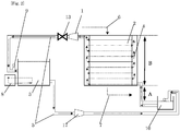
- the pressure at the bottom of the enclosed pressure-resistant jacket is higher than that at the top of the jacket when the suction pump stops, whereby it is possible to allow the cooling or heating medium in the enclosed pressure-resistant jacket to flow at a pressure lower than the pressure x (atm) applied within the fluid storage tank (also when the pump stops) by setting the pressure at the bottom of the jacket during stopping (cessation) of the suction pump at a pressure not higher than the pressure x (atm) applied within the fluid storage tank, preferably lower than the pressure x.
- the pressure at the bottom of the jacket is lower than that during cessation of the suction pump, and thus the pressure at the bottom of the jacket becomes lower than the pressure x (atm) applied within the fluid storage tank.
- These heights A and B are adjusted to enable safe circulation considering the suction height of a cooling or heating medium by the suction pump C, the specific density of the cooling or heating medium, a required difference in pressure (atm) between a pressure (atm) at the bottom of the enclosed pressure-resistant jacket and the pressure x (atm) within the fluid storage tank, a safe operational value, and atmospheric pressure.
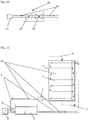
- An air pool 9 may be provided in the in a cooling or heating medium flow pipe 5 arranged between the suction pump 1 and the cooling or heating medium-storage tank 3, preferably near the cooling or heating medium-storage tank 3, and at a height not higher than the liquid level of the cooling or heating medium-storage tank 3.
- the temperature of the cooling or heating medium in the cooling or heating medium-storage tank 3 can be controlled by a temperature-control equipment 8.
- the inside of the cooling or heating medium-storage tank and the enclosed pressure-resistant jacket are connected by a conduit line optionally via a cooling or heating medium-receiver tank 11, and the exit, usually arranged at the top, of the enclosed pressure-resistant jacket and an admission port of the suction pump 1 are connected by a conduit line, and further a discharge port of the suction pump 1 and the inside of the cooling or heating medium-storage tank 3 are connected by a conduit line.
- cooling or heating medium-storage tank It is necessary to provide the cooling or heating medium-storage tank with a ventilation hole (ventilation pipe). This is because it is necessary for the cooling or heating medium-storage tank 3 to be open to the air instead of making it closed.
- the reason therefor is that by returning a pressurized state of the returning (returning from suction pump 1 to cooling or heating medium-storage tank 3) cooling or heating medium in the conduit line to a normal pressure state, a conduit line for forwarding (forwarding from the cooling or heating medium-storage tank 3 to the enclosed pressure-resistant jacket 4) cooling or heating medium can be always maintained in a reduced state.
- the method and plat for preventing contamination of a fluid in a fluid storage tank 2 with a cooling or heating medium by making an enclosed pressure-resistant jacket 4 provided around the outer wall of the fluid storage tank 2 in a pressure-reduced state are meant a method and plant in which the enclosed pressure-resistant jacket 4 is always maintained in a pressure-reduced state (a state which is relatively lower in pressure compared with a pressure within the fluid storage tank 2), and the method and plant are not necessarily restricted to the embodiments shown above.
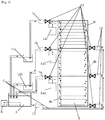
- the enclosed pressure-resistant jacket is constructed to a multiple staged (multistage) construction having a server tank and/or a pressure-reduction unit, if necessary, and a suction pump in each stage.
- the height A' from the liquid level of each server tank to the bottom of the corresponding enclosed pressure-resistant jacket is preferably set to satisfy the following equation (5'): A ′ ⁇ W 1 ⁇ x + d / ⁇ (wherein W, x, d and ⁇ are as defined above).
- a cooling or heating medium-server tank 10a, 10b or 10c is provided in each stage, and each server tank is arranged so that the liquid level of each server tank is below the bottom of each enclosed pressure-resistant jacket 4a, 4b, 4c.
- a suction pump 1a, 1b, 1c is provided between the exit of each enclosed pressure-resistant jacket 4a, 4b, 4c and a cooling or heating medium-storage tank 3.
- a cooling or heating medium-receiver tank 11b, 11c may be provided between the suction pump 1b, 1c in the second or subsequent stages and the cooling or heating medium-storage tank 3 ( Fig. 5 ).
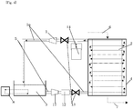
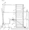
- a cooling or heating medium may be supplied directly from a cooling or heating medium-storage tank 3 to the bottom of each enclosed pressure-resistant jacket 4a, 4b, 4c by means of a pressure-reduction unit 12 provided in each stage as shown in Figs. 7 and 8 .
- a physically pressure-reducing apparatus 14a, 14b or 14c, and an electromagnetic valve 13 are provided in each stage, and a cooling or heating medium-receiver tank 11b or 11c is provided in the second and subsequent stages.
- a cooling or heating medium-receiver tank 11b or 11c is provided in the second and subsequent stages.
- a physically pressure-reducing apparatus 14 and an electromagnetic valve 13 are provided only in the first stage, and in the second and subsequent stages, suction pumps 1b and 1c are omitted but, in place of the suction pump, a T-shaped piping 16 for supplying a priming water at the commencement of operation and a valve 15 are provided in each of the conduit lines between each of the exit of enclosed pressure-resistant jackets 4b, 4c in the second or subsequent stage and a cooling or heating medium-storage tank 3.
- the cooling or heating medium usable in the present invention is a medium which is usually liquid at atmospheric pressure, and includes both of a cooling medium and a heating medium.
- the cooling medium is meat a liquid for cooling a fluid in a fluid storage tank, and examples thereof include a cooling water and antifreeze liquid (generally an ethylene glycol liquid or propylene glycol liquid) cooled by a refrigeration unit.
- the cooling medium in the cooling or heating medium-storage tank is cooled to approximately from - 0 to 5 °C, usually approximately from -2 to 2°C by a cooling apparatus, as necessary.
- the heating medium is meat a liquid for heating a fluid in the fluid storage tank
- examples of the heating medium usable in the present invention include a hot water or hot oil heated by a heating apparatus.
- the cooling medium and the heating medium mentioned above flows within the enclosed pressure-resistant jacket under conditions of temperature and pressure under which they are in a liquid state.
- Pressure-reduction unit 12 usable in the embodiments shown in Figs. 4 , 7 and 8 consists of a pressure-reduction valve 18 and a differential pressure valve 19, as shown in Fig. 10 .
- Pressure-reduction unit 12 can reduce and maintain at a constant value the pressure of the cooling or heating medium pressurized by pressurizing pump 17 by means of the pressure-reduction valve 18, and can achieve a pressure-reduced state by the differential pressure valve 19. If the pressure of the cooling or heating medium which has passed through the pressure-reduction valve 18 is too low (for example, 2 atm or lower), pressure reduction by the differential pressure valve 19 may become difficult to act.
Landscapes
- Engineering & Computer Science (AREA)
- Mechanical Engineering (AREA)
- Physical Or Chemical Processes And Apparatus (AREA)
- Filling Or Discharging Of Gas Storage Vessels (AREA)
- Jet Pumps And Other Pumps (AREA)
Claims (11)
- Verfahren zum Verhindern der Kontamination eines Fluids in einem Fluidspeicherbehälter (2) unter einem vorbestimmten Druck x mit einem flüssigen Kühl- oder Wärmemedium aufgrund eines Bruchs einer Wand des Fluidspeicherbehälters (2), in dem die Temperatur davon gesteuert wird, indem das Kühl- und Wärmemedium in einem geschlossenen druckfesten Mantel (4) strömen gelassen wird, der um eine äußere Wand des Fluidspeicherbehälters (2) bereitgestellt ist, wobei das Verfahren das Strömenlassen des Kühl- oder Wärmemediums in dem geschlossenen druckfesten Mantel (4) bei einem Druck umfasst, der niedriger als der Druck x ist, der innerhalb des Fluidspeicherbehälters angelegt wird,
wobei das Kühl- oder Wärmemedium in dem geschlossenen druckfesten Mantel bei einem Druck, der niedriger als der Druck x ist, der an den Fluidspeicherbehälter angelegt wird, durch Folgendes strömen gelassen wird:Einstellen eines Flüssigkeitspegels eines Kühl- oder Wärmemedium-Speicherbehälters (3), der Luft ausgesetzt ist, oder in einem Kühl- oder Wärmemedium zuführenden Abgabebehälter (10), der Luft ausgesetzt und separat von dem Fluidspeicherbehälter (2) bei einem Pegel bereitgestellt ist, bei einer Höhe, die um eine Höhe A niedriger als der Boden des geschlossenen druckfesten Mantels (4) ist;Saugen des Kühl- oder Wärmemediums mittels einer Saugpumpe (1), die mit einem Ausgang des Kühl- oder Wärmemediums in dem geschlossenen druckfesten Mantel (4) verbunden ist;Übertragen des Kühl- oder Wärmemediums von dem Kühl- oder Wärmemedium-Speicherbehälter (3) oder dem Abgabebehälter (10) durch eine Kanalleitung (5) zu dem geschlossenen druckfesten Mantel (4);Strömenlassen und Zirkulierenlassen des Kühl- oder Wärmemediums durch den geschlossenen druckfesten Mantel (4); undRückführen des Kühl- oder Wärmemediums zum Kühl- oder Wärmemedium-Speicherbehälter (3) oder dem Abgabebehälter (10) durch die Saugpumpe (1), wodurch das Kühl- oder Wärmemedium durch den geschlossenen druckfesten Mantel (4) geleitet wird,wobei die Höhe A des Flüssigkeitspegels des Kühl- oder Wärmemedium-Speicherbehälters (3) oder Abgabebehälters (10) zum Boden des geschlossenen druckfesten Mantels (4) derart eingestellt wird, dass die folgende Gleichung erfüllt ist: W eine Wassersaughöhe unter einem Vakuum ist;x ein Druck ist, der an die Innenseite des Fluidspeicherbehälters angelegt wird;d eine Differenz hinsichtlich des Drucks zwischen dem Druck x innerhalb des Fluidspeicherbehälters und einem Druck am Boden des geschlossenen druckfesten Mantels ist, wobei d>0 ist;ρ eine spezifische Dichte des Kühl- oder Wärmemediums ist, wobei die Beziehung zwischen der Höhe A, einer Höhe B des geschlossenen druckfesten Mantels vom Boden zur Oberseite davon und einer Saughöhe C des Kühl- oder Wärmemediums mittels der Saugpumpe die folgenden Gleichung erfüllt:
 wobei Cmax eine maximale Saughöhe des Kühl- oder Wärmemediums durch die Saugpumpe ist, mit der Maßgabe, dass die Cmax eine Saughöhe ist, wenn das Kühl- oder Wärmemedium als Wasser betrachtet wird;S ein sicherer Betriebswert ist und größer als 0 ist undp und A wie oben definiert sind.
 - Verfahren zum Verhindern der Kontamination eines Fluids in einem Fluidspeicherbehälter (2) unter einem vorbestimmten Druck x mit einem flüssigen Kühl- oder Wärmemedium aufgrund eines Bruchs einer Wand des Fluidspeicherbehälters (2), in dem die Temperatur davon gesteuert wird, indem das Kühl- und Wärmemedium in einem geschlossenen druckfesten Mantel (4) strömen gelassen wird, der um eine äußere Wand des Fluidspeicherbehälters (2) bereitgestellt ist, wobei das Verfahren das Strömenlassen des Kühl- oder Wärmemediums in dem geschlossenen druckfesten Mantel (4) bei einem Druck umfasst, der niedriger als der Druck x ist, der innerhalb des Fluidspeicherbehälters angelegt wird, wobei das Kühl- oder Wärmemedium in dem geschlossenen druckfesten Mantel (4) bei einem Druck, der niedriger als der Druck x ist, der an den Fluidspeicherbehälter angelegt wird, durch Folgendes strömen gelassen wird:Bereitstellen einer Druckreduzierungseinheit (12) zwischen einem Kühl- oder Wärmemedium-Speicherbehälter (3), der Luft ausgesetzt ist, und dem Fluidspeicherbehälter (2);Saugen des Kühl- oder Wärmemediums mittels einer Saugpumpe (1), die mit einem Ausgang des Kühl- oder Wärmemediums in dem geschlossenen druckfesten Mantel (4) verbunden ist;Übertragen des Kühl- oder Wärmemediums von dem Kühl- oder Wärmemedium-Speicherbehälter (3) durch die Druckreduzierungsleitung (12) zu dem geschlossenen druckfesten Mantel (4);Strömenlassen und Zirkulierenlassen des Kühl- oder Wärmemediums durch den geschlossenen druckfesten Mantel (4); undRückführen des Kühl- oder Wärmemediums zum Kühl- oder Wärmemedium-Speicherbehälter (3) durch die Saugpumpe (1), wodurch das Kühl- oder Wärmemedium durch den geschlossenen druckfesten Mantel (4) geleitet wird, wobei eine Höhe B vom Boden des geschlossenen druckfesten Mantels zur Oberseite davon derart eingestellt wird, dass die folgende Gleichung erfüllt ist:
 C eine Saughöhe des Kühl- oder Wärmemediums durch die Saugpumpe ist und
 Cmax eine maximale Saughöhe von Wasser durch die Saugpumpe ist, mit der Maßgabe, dass die Cmax eine Saughöhe ist, wenn das Kühl- oder Wärmemedium als Wasser betrachtet wird;S ein sicherer Betriebswert ist und größer als 0 ist;ρ eine spezifische Dichte des Kühl- oder Wärmemediums ist;W eine Wassersaughöhe unter einem Vakuum ist;E ein Druck ist, der bei der Druckreduzierungseinheit eingestellt wird, wobei
 x ein Druck ist, der an die Innenseite des Fluidspeicherbehälters angelegt wird;d eine Differenz hinsichtlich eines Drucks ist, wobei ein Druck am Boden des geschlossenen druckfesten Mantels vom Druck x innerhalb des Fluidspeicherbehälters subtrahiert wird, wobei die Differenz erforderlich ist, wenn die Saugpumpe angehalten wird, wobei d>0 ist.
 - Verfahren nach einem der Ansprüche 1 bis 2, ferner umfassend das Erkennen von Rissen des Fluidspeicherbehälters durch Abtasten des Kühl- oder Wärmemediums aus einem Luftpool, der in einem Durchgang des Kühl- oder Wärmemediums bereitgestellt ist, und Analysieren der Bestandteile des Kühl- oder Wärmemediums, während eine Kontamination des Fluids in dem Fluidspeicherbehälter mit dem flüssigen Kühl- oder Wärmemedium verhindert wird.
- Verfahren nach einem der Ansprüche 1 bis 2, wobei der Druck eines Raums, in dem das Kühl- oder Wärmemedium strömt, physikalisch und zwangsweise reduziert wird, während die Strömung des Kühl- oder Wärmemediums angehalten und der Raum versiegelt wird.
- Anlage, in der eine Kontamination eines Fluids in einem Fluidspeicherbehälter (2) unter einem vorbestimmten Druck x mit einem flüssigen Kühl- oder Wärmemedium aufgrund eines Bruchs einer Wand des Fluidspeicherbehälters (2) verhindert wird, die Temperatur des Fluids in dem Fluidspeicherbehälter (2) gesteuert wird, indem das Kühl- und Wärmemedium durch einen geschlossenen druckfesten Mantel (4) strömen gelassen wird, der um eine äußere Wand des Fluidspeicherbehälters bereitgestellt ist; wobei das Kühl- oder Wärmemedium in dem geschlossenen druckfesten Mantel (4) bei einem Druck strömen gelassen wird, der niedriger als der vorbestimmte Druck x innerhalb des Fluidspeicherbehälters ist; und der Druck in dem Mantel (4) niedriger als der Druck x gehalten wird,
wobei die Anlage Folgendes umfasst:(a) einen Fluidspeicherbehälter (2), der unter dem vorbestimmten Druck x steht;(b) den geschlossenen druckfesten Mantel (4), um das Kühl- oder Wärmemedium darin strömen und zirkulieren zu lassen, wobei der Mantel (4) um die äußere Wand des Fluidspeicherbehälters (2) bereitgestellt ist;(c) einen Kühl- oder Wärmemedium-Speicherbehälter (3) oder einen Kühl- oder Wärmemedium zuführenden Abgabebehälter (10), der separat von dem Fluidspeicherbehälter bereitgestellt ist, wobei der Mediumspeicherbehälter oder der Abgabebehälter eine Entlüftung aufweist und an seinem einen Ende mit dem geschlossenen druckfeste Mantel durch eine Kanalleitung verbunden sind, wobei der Flüssigkeitspegel des Kühl- oder Wärmemedium-Speicherbehälters oder des Kühl- oder Wärmemedium zuführenden Abgabebehälters bei einem Pegel eingestellt wird, der um eine Höhe A niedriger als der Boden des geschlossenen druckfesten Mantels (4) ist; und(d) eine Saugpumpe, die an ihrem einen Ende mit einem Ausgang des Kühl- oder Wärmemediums in dem geschlossenen druckfesten Mantel verbunden ist und an dem anderen Ende mit dem Kühl- oder Wärmemedium-Speicherbehälter oder dem Abgabebehälter verbunden ist;
wobei die Höhe A des Flüssigkeitspegels des Fluidspeicherbehälters oder des Abgabebehälters zum Boden des geschlossenen druckfesten Mantels derart eingestellt wird, dass die folgende Gleichung erfüllt ist: W eine Wassersaughöhe unter einem Vakuum ist;x ein Druck ist, der an die Innenseite des Fluidspeicherbehälters angelegt wird;d eine Differenz hinsichtlich eines Drucks ist, wobei ein Druck am Boden des geschlossenen druckfesten Mantels vom Druck x innerhalb des Fluidspeicherbehälters subtrahiert wird, wobei d>0 ist;ρ eine spezifische Dichte des Kühl- oder Wärmemediums ist;wobei die Beziehung zwischen der Höhe A, einer Höhe B des geschlossenen druckfesten Mantels vom Boden zur Oberseite davon und einer Saughöhe C des Kühl- oder Wärmemediums mittels der Saugpumpe die folgenden Gleichung erfüllt:
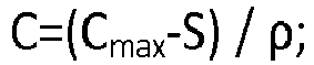 wobei Cmax eine maximale Saughöhe des Kühl- oder Wärmemediums durch die Saugpumpe ist, mit der Maßgabe, dass die Cmax eine Saughöhe ist, wenn das Kühl- oder Wärmemedium als Wasser betrachtet wird;S ein sicherer Betriebswert ist und größer als 0 ist; undρ und A wie oben definiert sind, wodurch das Kühl- oder Wärmemedium in dem geschlossenen druckfesten Mantel bei einem Druck strömen gelassen wird, der niedriger als der Druck x ist.
 - Anlage, in der eine Kontamination eines Fluids in einem Fluidspeicherbehälter (2) unter einem vorbestimmten Druck x mit einem flüssigen Kühl- oder Wärmemedium aufgrund eines Bruchs einer Wand des Fluidspeicherbehälters (2) verhindert wird; die Temperatur des Fluids in dem Fluidspeicherbehälter (2) gesteuert wird, indem das Kühl- und Wärmemedium durch einen geschlossenen druckfesten Mantel (4) strömen gelassen wird, der um eine äußere Wand des Fluidspeicherbehälters bereitgestellt ist; wobei das Kühl- oder Wärmemedium in dem geschlossenen druckfesten Mantel (4) bei einem Druck strömen gelassen wird, der niedriger als der vorbestimmte Druck x innerhalb des Fluidspeicherbehälters ist; und der Druck in dem Mantel (4) niedriger als der Druck x gehalten wird,
wobei die Anlage Folgendes umfasst:(a) einen Fluidspeicherbehälter (2), der unter dem vorbestimmten Druck x steht;(b) den geschlossenen druckfesten Mantel (4), um das Kühl- oder Wärmemedium darin strömen und zirkulieren zu lassen, wobei der Mantel (4) um die äußere Wand des Fluidspeicherbehälters (2) bereitgestellt ist;(c) einen Kühl- oder Wärmemedium-Speicherbehälter (3), der eine Entlüftung aufweist und an seinem einen Ende mit dem geschlossenen druckfesten Mantel (4) durch eine Kanalleitung (5) verbunden ist;(d) eine Saugpumpe (1), die an ihrem einen Ende mit einem Ausgang des Kühl- oder Wärmemediums in dem geschlossenen druckfesten Mantel (4) verbunden ist und an dem anderen Ende durch eine andere Kanalleitung (5) mit dem Kühl- oder Wärmemedium-Speicherbehälter (3) verbunden ist;(e) eine Druckreduzierungseinheit (12), die an ihrem einen Ende durch die Kanalleitung (5) mit dem Boden des geschlossenen druckfesten Mantels (4) verbunden ist und an ihrem anderen Ende durch die Kanalleitung (5) mit dem Kühl- oder Wärmemedium-Speicherbehälter (3) verbunden ist,
wobei eine Höhe B vom Boden des geschlossenen druckfesten Mantels zur Oberseite davon derart eingestellt wird, dass die folgende Gleichung erfüllt ist: C eine Saughöhe des Kühl- oder Wärmemediums durch die Saugpumpe ist und
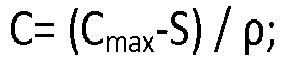 Cmax eine maximale Saughöhe von Wasser durch die Saugpumpe ist, mit der Maßgabe, dass die Cmax eine Saughöhe ist, wenn das Kühl- oder Wärmemedium Wasser ist;S ein sicherer Betriebswert ist und größer als 0 ist;ρ eine spezifische Dichte des Kühl- oder Wärmemediums ist;W eine Wassersaughöhe unter einem Vakuum ist;E ein Druck ist, der bei der Druckreduzierungseinheit eingestellt wird, wobeiwodurch das Kühl- oder Wärmemedium in dem geschlossenen druckfesten Mantel bei einem Druck strömen gelassen wird, der niedriger als der Druck x ist.
 x ein Druck ist, der an die Innenseite des Fluidspeicherbehälters angelegt wird;d eine Differenz hinsichtlich eines Drucks ist, wobei ein Druck am Boden des geschlossenen druckfesten Mantels vom Druck x innerhalb des Fluidspeicherbehälters subtrahiert wird, wobei die Differenz erforderlich ist, wenn die Saugpumpe angehalten wird, wobei d>0 ist,
 - Anlage nach Anspruch 5 oder 6, wobei die Druckdifferenz d in einem Bereich von 0,2 bis 0,4 Atm liegt.
- Anlage nach einem der Ansprüche 5 bis 7, wobei der Fluidspeicherbehälter ein größerer Behälter ist, der eine Höhe B aufweist, welche die Höhe C der Saughöhe des Kühl- oder Wärmemediums durch die Saugpumpe überschreitet, der geschlossene druckfeste Mantel eine mehrstufige Konstruktion mit nicht weniger als 2-stufigen geschlossenen druckfesten Mänteln ist, wobei die erste Stufe die Struktur des geschlossenen druckfesten Mantels nach Anspruch 5 oder 6 aufweist, jede der zweiten und nachfolgenden Stufen mit (i) einem geschlossenen druckfesten Mantel (4b, 4c) und (ii) einem eines (a) Kühl- oder Wärmemedium zuführenden Abgabebehälters, der separat von dem Fluidspeicherbehälter versehen ist, oder (b) einer Druckreduzierungseinheit (12) versehen ist, wobei der Abgabebehälter oder die Druckreduzierungseinheit zwischen dem Kühl- oder Wärmemedium-Speicherbehälter und dem Boden jedes geschlossenen druckfesten Mantels angeordnet sind,
wobei in dem Fall, dass der Abgabebehälter bereitgestellt ist, die Höhe A' von einem Flüssigkeitspegel jedes Abgabebehälters zum Boden jedes geschlossenen druckfesten Mantels derart eingestellt ist, dass die folgende Gleichung erfüllt ist:


- Anlage nach einem der Ansprüche 5 oder 6, wobei ein Luftpool zum Abtasten des Kühl- oder Wärmemediums in einem Durchgang des Kühl- oder Wärmemediums bereitgestellt ist, um die Bestandteile des Kühl- oder Wärmemediums zu analysieren.
- Anlage nach Anspruch 6, wobei die Druckreduzierungseinheit (12) ein Druckreduzierungsventil (18) zum Reduzieren des druckbeaufschlagten Kühl- oder Wärmemediums und Halten dieses bei einem konstanten Druck und ein Druckdifferenzventil (19) zum weiteren Reduzieren des Drucks des Kühl- oder Wärmemediums umfasst.
- Anlage nach einem der Ansprüche 5 bis 7, ferner umfassend eine physikalisch druckreduzierende Vorrichtung zum physikalischen und zwangsweise Reduzieren des Drucks in einem Raum, in dem das Kühl- oder Wärmemedium strömt, während die Strömung des Kühl- oder Wärmemediums gestoppt und der Raum versiegelt wird.
Applications Claiming Priority (2)
| Application Number | Priority Date | Filing Date | Title |
|---|---|---|---|
| JP2010092479A JP4707764B1 (ja) | 2010-04-13 | 2010-04-13 | 温度管理を要する流動体貯蔵タンク内の汚染防止方法、およびその装置 |
| PCT/JP2011/059031 WO2011129306A1 (ja) | 2010-04-13 | 2011-04-11 | 温度管理を要する流動体貯蔵タンク内の汚染防止方法、およびその装置 |
Publications (3)
| Publication Number | Publication Date |
|---|---|
| EP2559637A1 EP2559637A1 (de) | 2013-02-20 |
| EP2559637A4 EP2559637A4 (de) | 2015-07-01 |
| EP2559637B1 true EP2559637B1 (de) | 2017-09-06 |
Family
ID=44292610
Family Applications (1)
| Application Number | Title | Priority Date | Filing Date |
|---|---|---|---|
| EP11768827.5A Not-in-force EP2559637B1 (de) | 2010-04-13 | 2011-04-11 | Verfahren zur kontaminationsverhinderung in einem flüssigkeitsspeichertank mit temperatursteuerungserfordernis und vorrichtung dafür |
Country Status (12)
| Country | Link |
|---|---|
| US (3) | US9248480B2 (de) |
| EP (1) | EP2559637B1 (de) |
| JP (1) | JP4707764B1 (de) |
| KR (1) | KR101821434B1 (de) |
| CN (1) | CN102985342B (de) |
| AU (1) | AU2011242003B2 (de) |
| BR (1) | BR112012025924B1 (de) |
| CA (1) | CA2795434C (de) |
| ES (1) | ES2642279T3 (de) |
| MX (1) | MX2012011683A (de) |
| RU (1) | RU2564583C2 (de) |
| WO (1) | WO2011129306A1 (de) |
Families Citing this family (5)
| Publication number | Priority date | Publication date | Assignee | Title |
|---|---|---|---|---|
| NL2009749C2 (nl) | 2012-11-02 | 2014-05-06 | Eeuwe Durk Kooi | Tankcontainer. |
| US10788269B2 (en) * | 2016-11-07 | 2020-09-29 | Wabash National, L.P. | Cooling system for mobile bulk tanks |
| CN111186650A (zh) * | 2020-01-16 | 2020-05-22 | 海口海关技术中心 | 一种具有防潮保鲜隔热功能的中转储存罐 |
| CN113859787B (zh) * | 2021-09-03 | 2023-03-21 | 中建材创新科技研究院有限公司 | 一种料温可控的石膏料仓 |
| CN116395288B (zh) * | 2023-05-22 | 2025-11-18 | 上海泓济环保科技股份有限公司 | 零排放蒸发母液自动恒温储存设备 |
Family Cites Families (24)
| Publication number | Priority date | Publication date | Assignee | Title |
|---|---|---|---|---|
| US1987917A (en) * | 1933-02-04 | 1935-01-15 | Heil Co | Refrigerated tank |
| US2434956A (en) * | 1945-11-05 | 1948-01-27 | Spencer S Prentiss | Liquid oxygen "walkaround" unit |
| US3143167A (en) * | 1961-05-19 | 1964-08-04 | Tung Sol Electric Inc | Temperature controlled enclosure for testing purposes |
| US3451225A (en) * | 1968-02-08 | 1969-06-24 | Daryl G Hill | Water-jacket warmer for stationary fuel tank |
| US4298060A (en) * | 1979-02-14 | 1981-11-03 | Elliott Turbomachinery Limited | Fluid jacket for a vessel |
| US4261415A (en) * | 1979-10-19 | 1981-04-14 | Autoclave Engineers, Inc. | Method and apparatus for cooling a pressure vessel |
| US4502531A (en) * | 1983-02-28 | 1985-03-05 | Allied Corporation | High-pressure vessel furnace |
| DE3643557A1 (de) | 1986-12-19 | 1988-06-23 | Westerwaelder Eisen Gerhard | Temperierbarer tankcontainer |
| US4882912A (en) | 1988-10-12 | 1989-11-28 | Container Design Limited | Temperature controllable tank container |
| US5170659A (en) * | 1991-04-08 | 1992-12-15 | Kemp Development Corporation | Apparatus and method for detecting fluid leakage |
| US5552039A (en) * | 1994-07-13 | 1996-09-03 | Rpc Waste Management Services, Inc. | Turbulent flow cold-wall reactor |
| JP3593406B2 (ja) | 1995-12-15 | 2004-11-24 | 株式会社テイエルブイ | 減圧加熱冷却装置 |
| US5743023A (en) * | 1996-09-06 | 1998-04-28 | Fay; John M. | Method and apparatus for controlling freeze drying process |
| US6610250B1 (en) * | 1999-08-23 | 2003-08-26 | 3M Innovative Properties Company | Apparatus using halogenated organic fluids for heat transfer in low temperature processes requiring sterilization and methods therefor |
| JP2001088894A (ja) * | 1999-09-21 | 2001-04-03 | Nihon Tetra Pak Kk | タンク装置 |
| JP3587513B2 (ja) * | 2001-04-26 | 2004-11-10 | 株式会社ロッコーエンジニアリング | 冷却タンク |
| CN1417527A (zh) * | 2001-11-02 | 2003-05-14 | 量子能技术股份有限公司 | 改进的水加热器 |
| JP2004316992A (ja) | 2003-04-15 | 2004-11-11 | Tlv Co Ltd | 間接熱交換器 |
| US7870891B2 (en) * | 2004-05-29 | 2011-01-18 | Kilr-Chilr, Llc | Systems, devices and methods for regulating temperatures of tanks, containers and contents therein |
| JP4068108B2 (ja) * | 2005-11-04 | 2008-03-26 | 大陽日酸株式会社 | 熱媒加熱冷却装置 |
| CN2851175Y (zh) * | 2005-11-23 | 2006-12-27 | 中国石油天然气股份有限公司 | 滩海油田温度、压力自控天然气加热储油罐装置 |
| US7832466B2 (en) * | 2006-11-29 | 2010-11-16 | Abdullah Ahmad Al-Hashash | Water supply system |
| KR100857551B1 (ko) | 2007-03-07 | 2008-09-09 | 세메스 주식회사 | 액체 공급 장치 |
| JP2009293844A (ja) | 2008-06-04 | 2009-12-17 | Chugoku Electric Power Co Inc:The | 高粘性液体燃料加温システム |
-
2010
- 2010-04-13 JP JP2010092479A patent/JP4707764B1/ja active Active
-
2011
- 2011-04-11 EP EP11768827.5A patent/EP2559637B1/de not_active Not-in-force
- 2011-04-11 CA CA2795434A patent/CA2795434C/en not_active Expired - Fee Related
- 2011-04-11 MX MX2012011683A patent/MX2012011683A/es active IP Right Grant
- 2011-04-11 CN CN201180019114.5A patent/CN102985342B/zh active Active
- 2011-04-11 AU AU2011242003A patent/AU2011242003B2/en not_active Ceased
- 2011-04-11 US US13/641,407 patent/US9248480B2/en active Active
- 2011-04-11 BR BR112012025924-5A patent/BR112012025924B1/pt not_active IP Right Cessation
- 2011-04-11 KR KR1020127029644A patent/KR101821434B1/ko not_active Expired - Fee Related
- 2011-04-11 WO PCT/JP2011/059031 patent/WO2011129306A1/ja not_active Ceased
- 2011-04-11 RU RU2012148126/12A patent/RU2564583C2/ru not_active IP Right Cessation
- 2011-04-11 ES ES11768827.5T patent/ES2642279T3/es active Active
-
2015
- 2015-12-22 US US14/978,043 patent/US10058903B2/en active Active
-
2018
- 2018-07-25 US US16/045,261 patent/US10562082B2/en active Active
Non-Patent Citations (1)
| Title |
|---|
| None * |
Also Published As
| Publication number | Publication date |
|---|---|
| US20160107208A1 (en) | 2016-04-21 |
| AU2011242003A1 (en) | 2012-10-25 |
| MX2012011683A (es) | 2013-02-21 |
| CA2795434C (en) | 2017-10-17 |
| BR112012025924B1 (pt) | 2019-11-19 |
| US20130192684A1 (en) | 2013-08-01 |
| US10562082B2 (en) | 2020-02-18 |
| JP2011219148A (ja) | 2011-11-04 |
| EP2559637A1 (de) | 2013-02-20 |
| EP2559637A4 (de) | 2015-07-01 |
| KR20130055602A (ko) | 2013-05-28 |
| RU2564583C2 (ru) | 2015-10-10 |
| CA2795434A1 (en) | 2011-10-20 |
| CN102985342A (zh) | 2013-03-20 |
| JP4707764B1 (ja) | 2011-06-22 |
| RU2012148126A (ru) | 2014-05-20 |
| BR112012025924A2 (pt) | 2016-06-28 |
| KR101821434B1 (ko) | 2018-01-23 |
| ES2642279T3 (es) | 2017-11-16 |
| US9248480B2 (en) | 2016-02-02 |
| WO2011129306A1 (ja) | 2011-10-20 |
| CN102985342B (zh) | 2015-06-17 |
| US20180326463A1 (en) | 2018-11-15 |
| US10058903B2 (en) | 2018-08-28 |
| AU2011242003B2 (en) | 2014-08-07 |
Similar Documents
| Publication | Publication Date | Title |
|---|---|---|
| US10562082B2 (en) | Method for contamination prevention in fluid storage tank requiring temperature control, and device therefor | |
| KR20230104918A (ko) | 다중-랙 액침 냉각 분배 시스템 | |
| US20190169011A1 (en) | Apparatuses, Systems, and Methods for Dispensing Beverages Using Alcoholic Concentrates | |
| US11197397B2 (en) | Provisioning data center server cooling equipment | |
| EP1780482A1 (de) | Kühlsystem für supraleitende antriebsvorrichtung | |
| US20060054404A1 (en) | Oil circulation retention system and method | |
| WO2002088611A1 (en) | Chiller tank system and method for chilling liquids | |
| KR101523228B1 (ko) | 가스를 매개체로 하는 반도체 제조공정설비용 온도 제어시스템의 냉매 충전시스템 및 이를 이용한 냉매 충전방법 | |
| CN106941311A (zh) | 变频器水冷控制系统 | |
| AU2019356968B2 (en) | System and method for separation of air from liquid | |
| EP3697205B1 (de) | Selbstausgleichendes geflügelwasserverteilsystem | |
| CN218501987U (zh) | 在线卸载催化剂装置 | |
| KR20130119368A (ko) | 저온 유지 장치용 압력 조절 시스템 | |
| JP2023033348A (ja) | シール水タンク | |
| EP3125680B1 (de) | Milchtank | |
| GB2502593A (en) | Modular cooler for alcoholic beverages | |
| KR101582276B1 (ko) | 낙수방지기능이 있는 냉각장치 |
Legal Events
| Date | Code | Title | Description |
|---|---|---|---|
| PUAI | Public reference made under article 153(3) epc to a published international application that has entered the european phase |
Free format text: ORIGINAL CODE: 0009012 |
|
| 17P | Request for examination filed |
Effective date: 20121003 |
|
| AK | Designated contracting states |
Kind code of ref document: A1 Designated state(s): AL AT BE BG CH CY CZ DE DK EE ES FI FR GB GR HR HU IE IS IT LI LT LU LV MC MK MT NL NO PL PT RO RS SE SI SK SM TR |
|
| XX | Miscellaneous (additional remarks) |
Free format text: THE APPLICANT FILED A TEXT BY WHICH IT IS INTENDED TO BRING THE TRANSLATION INTO CONFORMITY WITH THE ORIGINAL TEXT OF THE APPLICATION (ART.14(2) EPC). |
|
| DAX | Request for extension of the european patent (deleted) | ||
| REG | Reference to a national code |
Ref country code: DE Ref legal event code: R079 Ref document number: 602011041360 Country of ref document: DE Free format text: PREVIOUS MAIN CLASS: B65D0090220000 Ipc: B65D0088740000 |
|
| RA4 | Supplementary search report drawn up and despatched (corrected) |
Effective date: 20150529 |
|
| RIC1 | Information provided on ipc code assigned before grant |
Ipc: B65D 90/50 20060101ALI20150522BHEP Ipc: B65D 88/74 20060101AFI20150522BHEP |
|
| 17Q | First examination report despatched |
Effective date: 20160420 |
|
| STAA | Information on the status of an ep patent application or granted ep patent |
Free format text: STATUS: EXAMINATION IS IN PROGRESS |
|
| GRAP | Despatch of communication of intention to grant a patent |
Free format text: ORIGINAL CODE: EPIDOSNIGR1 |
|
| STAA | Information on the status of an ep patent application or granted ep patent |
Free format text: STATUS: GRANT OF PATENT IS INTENDED |
|
| INTG | Intention to grant announced |
Effective date: 20170404 |
|
| GRAS | Grant fee paid |
Free format text: ORIGINAL CODE: EPIDOSNIGR3 |
|
| GRAA | (expected) grant |
Free format text: ORIGINAL CODE: 0009210 |
|
| STAA | Information on the status of an ep patent application or granted ep patent |
Free format text: STATUS: THE PATENT HAS BEEN GRANTED |
|
| AK | Designated contracting states |
Kind code of ref document: B1 Designated state(s): AL AT BE BG CH CY CZ DE DK EE ES FI FR GB GR HR HU IE IS IT LI LT LU LV MC MK MT NL NO PL PT RO RS SE SI SK SM TR |
|
| REG | Reference to a national code |
Ref country code: GB Ref legal event code: FG4D |
|
| XX | Miscellaneous (additional remarks) |
Free format text: THE APPLICANT FILED A TEXT BY WHICH IT IS INTENDED TO BRING THE TRANSLATION INTO CONFORMITY WITH THE ORIGINAL TEXT OF THE APPLICATION (ART.14(2) EPC). |
|
| REG | Reference to a national code |
Ref country code: CH Ref legal event code: EP Ref country code: AT Ref legal event code: REF Ref document number: 925627 Country of ref document: AT Kind code of ref document: T Effective date: 20170915 |
|
| REG | Reference to a national code |
Ref country code: IE Ref legal event code: FG4D |
|
| REG | Reference to a national code |
Ref country code: DE Ref legal event code: R096 Ref document number: 602011041360 Country of ref document: DE |
|
| REG | Reference to a national code |
Ref country code: NL Ref legal event code: FP |
|
| REG | Reference to a national code |
Ref country code: ES Ref legal event code: FG2A Ref document number: 2642279 Country of ref document: ES Kind code of ref document: T3 Effective date: 20171116 |
|
| REG | Reference to a national code |
Ref country code: LT Ref legal event code: MG4D |
|
| PG25 | Lapsed in a contracting state [announced via postgrant information from national office to epo] |
Ref country code: LT Free format text: LAPSE BECAUSE OF FAILURE TO SUBMIT A TRANSLATION OF THE DESCRIPTION OR TO PAY THE FEE WITHIN THE PRESCRIBED TIME-LIMIT Effective date: 20170906 Ref country code: HR Free format text: LAPSE BECAUSE OF FAILURE TO SUBMIT A TRANSLATION OF THE DESCRIPTION OR TO PAY THE FEE WITHIN THE PRESCRIBED TIME-LIMIT Effective date: 20170906 Ref country code: SE Free format text: LAPSE BECAUSE OF FAILURE TO SUBMIT A TRANSLATION OF THE DESCRIPTION OR TO PAY THE FEE WITHIN THE PRESCRIBED TIME-LIMIT Effective date: 20170906 Ref country code: NO Free format text: LAPSE BECAUSE OF FAILURE TO SUBMIT A TRANSLATION OF THE DESCRIPTION OR TO PAY THE FEE WITHIN THE PRESCRIBED TIME-LIMIT Effective date: 20171206 Ref country code: FI Free format text: LAPSE BECAUSE OF FAILURE TO SUBMIT A TRANSLATION OF THE DESCRIPTION OR TO PAY THE FEE WITHIN THE PRESCRIBED TIME-LIMIT Effective date: 20170906 |
|
| REG | Reference to a national code |
Ref country code: AT Ref legal event code: MK05 Ref document number: 925627 Country of ref document: AT Kind code of ref document: T Effective date: 20170906 |
|
| PG25 | Lapsed in a contracting state [announced via postgrant information from national office to epo] |
Ref country code: BG Free format text: LAPSE BECAUSE OF FAILURE TO SUBMIT A TRANSLATION OF THE DESCRIPTION OR TO PAY THE FEE WITHIN THE PRESCRIBED TIME-LIMIT Effective date: 20171206 Ref country code: GR Free format text: LAPSE BECAUSE OF FAILURE TO SUBMIT A TRANSLATION OF THE DESCRIPTION OR TO PAY THE FEE WITHIN THE PRESCRIBED TIME-LIMIT Effective date: 20171207 Ref country code: RS Free format text: LAPSE BECAUSE OF FAILURE TO SUBMIT A TRANSLATION OF THE DESCRIPTION OR TO PAY THE FEE WITHIN THE PRESCRIBED TIME-LIMIT Effective date: 20170906 Ref country code: LV Free format text: LAPSE BECAUSE OF FAILURE TO SUBMIT A TRANSLATION OF THE DESCRIPTION OR TO PAY THE FEE WITHIN THE PRESCRIBED TIME-LIMIT Effective date: 20170906 |
|
| REG | Reference to a national code |
Ref country code: FR Ref legal event code: PLFP Year of fee payment: 8 |
|
| PG25 | Lapsed in a contracting state [announced via postgrant information from national office to epo] |
Ref country code: RO Free format text: LAPSE BECAUSE OF FAILURE TO SUBMIT A TRANSLATION OF THE DESCRIPTION OR TO PAY THE FEE WITHIN THE PRESCRIBED TIME-LIMIT Effective date: 20170906 Ref country code: PL Free format text: LAPSE BECAUSE OF FAILURE TO SUBMIT A TRANSLATION OF THE DESCRIPTION OR TO PAY THE FEE WITHIN THE PRESCRIBED TIME-LIMIT Effective date: 20170906 Ref country code: CZ Free format text: LAPSE BECAUSE OF FAILURE TO SUBMIT A TRANSLATION OF THE DESCRIPTION OR TO PAY THE FEE WITHIN THE PRESCRIBED TIME-LIMIT Effective date: 20170906 |
|
| PG25 | Lapsed in a contracting state [announced via postgrant information from national office to epo] |
Ref country code: EE Free format text: LAPSE BECAUSE OF FAILURE TO SUBMIT A TRANSLATION OF THE DESCRIPTION OR TO PAY THE FEE WITHIN THE PRESCRIBED TIME-LIMIT Effective date: 20170906 Ref country code: AT Free format text: LAPSE BECAUSE OF FAILURE TO SUBMIT A TRANSLATION OF THE DESCRIPTION OR TO PAY THE FEE WITHIN THE PRESCRIBED TIME-LIMIT Effective date: 20170906 Ref country code: IS Free format text: LAPSE BECAUSE OF FAILURE TO SUBMIT A TRANSLATION OF THE DESCRIPTION OR TO PAY THE FEE WITHIN THE PRESCRIBED TIME-LIMIT Effective date: 20180106 Ref country code: SK Free format text: LAPSE BECAUSE OF FAILURE TO SUBMIT A TRANSLATION OF THE DESCRIPTION OR TO PAY THE FEE WITHIN THE PRESCRIBED TIME-LIMIT Effective date: 20170906 Ref country code: SM Free format text: LAPSE BECAUSE OF FAILURE TO SUBMIT A TRANSLATION OF THE DESCRIPTION OR TO PAY THE FEE WITHIN THE PRESCRIBED TIME-LIMIT Effective date: 20170906 |
|
| REG | Reference to a national code |
Ref country code: DE Ref legal event code: R097 Ref document number: 602011041360 Country of ref document: DE |
|
| PLBE | No opposition filed within time limit |
Free format text: ORIGINAL CODE: 0009261 |
|
| STAA | Information on the status of an ep patent application or granted ep patent |
Free format text: STATUS: NO OPPOSITION FILED WITHIN TIME LIMIT |
|
| PG25 | Lapsed in a contracting state [announced via postgrant information from national office to epo] |
Ref country code: DK Free format text: LAPSE BECAUSE OF FAILURE TO SUBMIT A TRANSLATION OF THE DESCRIPTION OR TO PAY THE FEE WITHIN THE PRESCRIBED TIME-LIMIT Effective date: 20170906 |
|
| 26N | No opposition filed |
Effective date: 20180607 |
|
| PG25 | Lapsed in a contracting state [announced via postgrant information from national office to epo] |
Ref country code: SI Free format text: LAPSE BECAUSE OF FAILURE TO SUBMIT A TRANSLATION OF THE DESCRIPTION OR TO PAY THE FEE WITHIN THE PRESCRIBED TIME-LIMIT Effective date: 20170906 |
|
| PG25 | Lapsed in a contracting state [announced via postgrant information from national office to epo] |
Ref country code: MC Free format text: LAPSE BECAUSE OF FAILURE TO SUBMIT A TRANSLATION OF THE DESCRIPTION OR TO PAY THE FEE WITHIN THE PRESCRIBED TIME-LIMIT Effective date: 20170906 |
|
| PG25 | Lapsed in a contracting state [announced via postgrant information from national office to epo] |
Ref country code: LU Free format text: LAPSE BECAUSE OF NON-PAYMENT OF DUE FEES Effective date: 20180411 |
|
| PGFP | Annual fee paid to national office [announced via postgrant information from national office to epo] |
Ref country code: NL Payment date: 20190416 Year of fee payment: 9 |
|
| PGFP | Annual fee paid to national office [announced via postgrant information from national office to epo] |
Ref country code: IT Payment date: 20190418 Year of fee payment: 9 Ref country code: ES Payment date: 20190520 Year of fee payment: 9 Ref country code: IE Payment date: 20190426 Year of fee payment: 9 Ref country code: DE Payment date: 20190418 Year of fee payment: 9 |
|
| PGFP | Annual fee paid to national office [announced via postgrant information from national office to epo] |
Ref country code: FR Payment date: 20190416 Year of fee payment: 9 Ref country code: BE Payment date: 20190416 Year of fee payment: 9 |
|
| PGFP | Annual fee paid to national office [announced via postgrant information from national office to epo] |
Ref country code: CH Payment date: 20190416 Year of fee payment: 9 |
|
| PGFP | Annual fee paid to national office [announced via postgrant information from national office to epo] |
Ref country code: GB Payment date: 20190425 Year of fee payment: 9 |
|
| PG25 | Lapsed in a contracting state [announced via postgrant information from national office to epo] |
Ref country code: MT Free format text: LAPSE BECAUSE OF NON-PAYMENT OF DUE FEES Effective date: 20180411 |
|
| PG25 | Lapsed in a contracting state [announced via postgrant information from national office to epo] |
Ref country code: TR Free format text: LAPSE BECAUSE OF FAILURE TO SUBMIT A TRANSLATION OF THE DESCRIPTION OR TO PAY THE FEE WITHIN THE PRESCRIBED TIME-LIMIT Effective date: 20170906 |
|
| PG25 | Lapsed in a contracting state [announced via postgrant information from national office to epo] |
Ref country code: HU Free format text: LAPSE BECAUSE OF FAILURE TO SUBMIT A TRANSLATION OF THE DESCRIPTION OR TO PAY THE FEE WITHIN THE PRESCRIBED TIME-LIMIT; INVALID AB INITIO Effective date: 20110411 Ref country code: PT Free format text: LAPSE BECAUSE OF FAILURE TO SUBMIT A TRANSLATION OF THE DESCRIPTION OR TO PAY THE FEE WITHIN THE PRESCRIBED TIME-LIMIT Effective date: 20170906 |
|
| PG25 | Lapsed in a contracting state [announced via postgrant information from national office to epo] |
Ref country code: CY Free format text: LAPSE BECAUSE OF FAILURE TO SUBMIT A TRANSLATION OF THE DESCRIPTION OR TO PAY THE FEE WITHIN THE PRESCRIBED TIME-LIMIT Effective date: 20170906 Ref country code: MK Free format text: LAPSE BECAUSE OF NON-PAYMENT OF DUE FEES Effective date: 20170906 |
|
| PG25 | Lapsed in a contracting state [announced via postgrant information from national office to epo] |
Ref country code: AL Free format text: LAPSE BECAUSE OF FAILURE TO SUBMIT A TRANSLATION OF THE DESCRIPTION OR TO PAY THE FEE WITHIN THE PRESCRIBED TIME-LIMIT Effective date: 20170906 |
|
| REG | Reference to a national code |
Ref country code: DE Ref legal event code: R119 Ref document number: 602011041360 Country of ref document: DE |
|
| REG | Reference to a national code |
Ref country code: CH Ref legal event code: PL |
|
| REG | Reference to a national code |
Ref country code: NL Ref legal event code: MM Effective date: 20200501 |
|
| PG25 | Lapsed in a contracting state [announced via postgrant information from national office to epo] |
Ref country code: FR Free format text: LAPSE BECAUSE OF NON-PAYMENT OF DUE FEES Effective date: 20200430 Ref country code: LI Free format text: LAPSE BECAUSE OF NON-PAYMENT OF DUE FEES Effective date: 20200430 Ref country code: DE Free format text: LAPSE BECAUSE OF NON-PAYMENT OF DUE FEES Effective date: 20201103 Ref country code: CH Free format text: LAPSE BECAUSE OF NON-PAYMENT OF DUE FEES Effective date: 20200430 |
|
| REG | Reference to a national code |
Ref country code: BE Ref legal event code: MM Effective date: 20200430 |
|
| PG25 | Lapsed in a contracting state [announced via postgrant information from national office to epo] |
Ref country code: BE Free format text: LAPSE BECAUSE OF NON-PAYMENT OF DUE FEES Effective date: 20200430 |
|
| GBPC | Gb: european patent ceased through non-payment of renewal fee |
Effective date: 20200411 |
|
| PG25 | Lapsed in a contracting state [announced via postgrant information from national office to epo] |
Ref country code: NL Free format text: LAPSE BECAUSE OF NON-PAYMENT OF DUE FEES Effective date: 20200501 |
|
| PG25 | Lapsed in a contracting state [announced via postgrant information from national office to epo] |
Ref country code: GB Free format text: LAPSE BECAUSE OF NON-PAYMENT OF DUE FEES Effective date: 20200411 Ref country code: IE Free format text: LAPSE BECAUSE OF NON-PAYMENT OF DUE FEES Effective date: 20200411 |
|
| REG | Reference to a national code |
Ref country code: ES Ref legal event code: FD2A Effective date: 20210902 |
|
| PG25 | Lapsed in a contracting state [announced via postgrant information from national office to epo] |
Ref country code: IT Free format text: LAPSE BECAUSE OF NON-PAYMENT OF DUE FEES Effective date: 20200411 |
|
| PG25 | Lapsed in a contracting state [announced via postgrant information from national office to epo] |
Ref country code: ES Free format text: LAPSE BECAUSE OF NON-PAYMENT OF DUE FEES Effective date: 20200412 |