EP2559751A1 - Récipient destiné au prétraitement de matières organiques - Google Patents
Récipient destiné au prétraitement de matières organiques Download PDFInfo
- Publication number
- EP2559751A1 EP2559751A1 EP12180162A EP12180162A EP2559751A1 EP 2559751 A1 EP2559751 A1 EP 2559751A1 EP 12180162 A EP12180162 A EP 12180162A EP 12180162 A EP12180162 A EP 12180162A EP 2559751 A1 EP2559751 A1 EP 2559751A1
- Authority
- EP
- European Patent Office
- Prior art keywords
- container
- slide
- liquid
- chamber
- filling
- Prior art date
- Legal status (The legal status is an assumption and is not a legal conclusion. Google has not performed a legal analysis and makes no representation as to the accuracy of the status listed.)
- Granted
Links
Images



Classifications
-
- C—CHEMISTRY; METALLURGY
- C12—BIOCHEMISTRY; BEER; SPIRITS; WINE; VINEGAR; MICROBIOLOGY; ENZYMOLOGY; MUTATION OR GENETIC ENGINEERING
- C12M—APPARATUS FOR ENZYMOLOGY OR MICROBIOLOGY; APPARATUS FOR CULTURING MICROORGANISMS FOR PRODUCING BIOMASS, FOR GROWING CELLS OR FOR OBTAINING FERMENTATION OR METABOLIC PRODUCTS, i.e. BIOREACTORS OR FERMENTERS
- C12M21/00—Bioreactors or fermenters specially adapted for specific uses
- C12M21/04—Bioreactors or fermenters specially adapted for specific uses for producing gas, e.g. biogas
-
- C—CHEMISTRY; METALLURGY
- C12—BIOCHEMISTRY; BEER; SPIRITS; WINE; VINEGAR; MICROBIOLOGY; ENZYMOLOGY; MUTATION OR GENETIC ENGINEERING
- C12M—APPARATUS FOR ENZYMOLOGY OR MICROBIOLOGY; APPARATUS FOR CULTURING MICROORGANISMS FOR PRODUCING BIOMASS, FOR GROWING CELLS OR FOR OBTAINING FERMENTATION OR METABOLIC PRODUCTS, i.e. BIOREACTORS OR FERMENTERS
- C12M23/00—Constructional details, e.g. recesses, hinges
-
- C—CHEMISTRY; METALLURGY
- C12—BIOCHEMISTRY; BEER; SPIRITS; WINE; VINEGAR; MICROBIOLOGY; ENZYMOLOGY; MUTATION OR GENETIC ENGINEERING
- C12M—APPARATUS FOR ENZYMOLOGY OR MICROBIOLOGY; APPARATUS FOR CULTURING MICROORGANISMS FOR PRODUCING BIOMASS, FOR GROWING CELLS OR FOR OBTAINING FERMENTATION OR METABOLIC PRODUCTS, i.e. BIOREACTORS OR FERMENTERS
- C12M23/00—Constructional details, e.g. recesses, hinges
- C12M23/34—Internal compartments or partitions
-
- C—CHEMISTRY; METALLURGY
- C12—BIOCHEMISTRY; BEER; SPIRITS; WINE; VINEGAR; MICROBIOLOGY; ENZYMOLOGY; MUTATION OR GENETIC ENGINEERING
- C12M—APPARATUS FOR ENZYMOLOGY OR MICROBIOLOGY; APPARATUS FOR CULTURING MICROORGANISMS FOR PRODUCING BIOMASS, FOR GROWING CELLS OR FOR OBTAINING FERMENTATION OR METABOLIC PRODUCTS, i.e. BIOREACTORS OR FERMENTERS
- C12M33/00—Means for introduction, transport, positioning, extraction, harvesting, peeling or sampling of biological material in or from the apparatus
-
- C—CHEMISTRY; METALLURGY
- C12—BIOCHEMISTRY; BEER; SPIRITS; WINE; VINEGAR; MICROBIOLOGY; ENZYMOLOGY; MUTATION OR GENETIC ENGINEERING
- C12M—APPARATUS FOR ENZYMOLOGY OR MICROBIOLOGY; APPARATUS FOR CULTURING MICROORGANISMS FOR PRODUCING BIOMASS, FOR GROWING CELLS OR FOR OBTAINING FERMENTATION OR METABOLIC PRODUCTS, i.e. BIOREACTORS OR FERMENTERS
- C12M41/00—Means for regulation, monitoring, measurement or control, e.g. flow regulation
-
- C—CHEMISTRY; METALLURGY
- C12—BIOCHEMISTRY; BEER; SPIRITS; WINE; VINEGAR; MICROBIOLOGY; ENZYMOLOGY; MUTATION OR GENETIC ENGINEERING
- C12M—APPARATUS FOR ENZYMOLOGY OR MICROBIOLOGY; APPARATUS FOR CULTURING MICROORGANISMS FOR PRODUCING BIOMASS, FOR GROWING CELLS OR FOR OBTAINING FERMENTATION OR METABOLIC PRODUCTS, i.e. BIOREACTORS OR FERMENTERS
- C12M45/00—Means for pre-treatment of biological substances
- C12M45/06—Means for pre-treatment of biological substances by chemical means or hydrolysis
-
- Y—GENERAL TAGGING OF NEW TECHNOLOGICAL DEVELOPMENTS; GENERAL TAGGING OF CROSS-SECTIONAL TECHNOLOGIES SPANNING OVER SEVERAL SECTIONS OF THE IPC; TECHNICAL SUBJECTS COVERED BY FORMER USPC CROSS-REFERENCE ART COLLECTIONS [XRACs] AND DIGESTS
- Y02—TECHNOLOGIES OR APPLICATIONS FOR MITIGATION OR ADAPTATION AGAINST CLIMATE CHANGE
- Y02E—REDUCTION OF GREENHOUSE GAS [GHG] EMISSIONS, RELATED TO ENERGY GENERATION, TRANSMISSION OR DISTRIBUTION
- Y02E50/00—Technologies for the production of fuel of non-fossil origin
- Y02E50/30—Fuel from waste, e.g. synthetic alcohol or diesel
Definitions
- the invention makes a container for the pretreatment of organic substances, arranged in a plant for the production of biogas.
- a 1m x 2m opening is open for a longer time, about 0.5 to 2 hours per day. Since the substrate has to be stirred during filling, a strong odor nuisance occurs here.
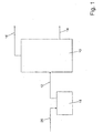
- FIG. 1 shows a section of the flow diagram of a biogas plant.
- a fermenter bears the reference numeral 10.
- the fermenter 10 has an inlet 12 and a drain 14 and a vent 16 for biogas.
- a container 18 is arranged at the inlet 12 of the fermenter 10.
- organic substances such as energy crops (eg maize and other crops, reed grass), residues such as crop residues (eg beet leaves), animal excreta (eg manure, manure), by-products of food production (eg fats, food particles, potato peels) or Organic wastes (eg sewage sludge) are introduced into the container 18, represented by arrow 20.
- energy crops eg maize and other crops, reed grass
- residues such as crop residues (eg beet leaves)
- animal excreta eg manure, manure
- by-products of food production eg fats, food particles, potato peels
- Organic wastes eg sewage sludge
- the filling of the container 18 with solids is carried out by a wheel loader, a front loader, a telescopic loader or similar construction machinery or agricultural machinery. Also conceivable is the filling of the container 18 by means of a conveyor belt from a dosing.
- the organic substances are mixed with liquid digestate or manure.
- a mixed substrate is then fed to the fermenter 10 in batches or in a small container volume.
- the microbial, anaerobic degradation of organic matter occurs.
- This biogas is generated, which is fed via the trigger 16 a cogeneration plant or one After treatment is supplied so that it can be fed as biomethane in a natural gas network.
- a dry or wet fermentation residue is discharged via the outlet 14 from the fermenter 10 and fed substantially for use as a fertilizer.
- the container 18 is usually made of concrete cylindrical hollow body, which has a rectangular insertion opening. To avoid odor, the throw-in opening according to the invention is provided with a lock system 22.
- the lock system 22 shows FIG. 2 in a front view. Shown is a section through the rectangular insertion opening 24 in a ceiling 26 of the container 18. The insertion opening 24 is filled with a first grid 27. The front view of the lock system 22 takes place from the direction of the approaching wheel loader.
- the lock system 22 comprises a first chamber 28, a second chamber 30.
- a first slide 32 is arranged between the throw-in opening 24 and the first chamber 28.
- the first slider 32 in a closed position, separates the first chamber 28 from an interior 34 of the container 18.
- a second slider 36 is disposed between the first chamber 28 and the second chamber 30.
- the second slider 36 separates the first chamber 28 from the second chamber 30 in a closed position.
- the second chamber 30 is bounded above by a second grid 38.
- the dimensions of the chambers 28, 30 are adapted to a volume of the wheel loader bucket.
- the Gitterost 38 is limited to a left in the drawing, right and rear side, each having a wall.
- the three walls are for example made of stainless steel sheets and form a kind of funnel 40, which is open to a Be Heilllseite 42, that is to the wheel loader.
- a slight inclination of the walls from the second grid 38 away, allows a widening of a lock opening on the width of the blade of the wheel loader.
- the organic matter slides easily and without loss to the second grid 38 and the second chamber 30.
- the second Gitterost 38 is not essential to the invention insofar as the invention works without him.
- the second grate 38 is sometimes required for accident prevention by the competent authorities.
- the same principles also apply to the first grating 27.
- the hopper 40 can be supported separately in order to avoid damage to a weighing device 44, which is explained in more detail below.
- the second slide 36 serves as a weighing device 44 in a closed position.
- the weighing device 44 comprises four weighing cells 50 arranged on the circumference of the second slide 36 and four weighing plates 46 Weighing plates 46 are arranged on four separate supports 48; alternatively, the frame 51 of the lower chamber 28 can be made so strong that the weighing pins can be mounted on it.
- the four load cells 50 are fixedly installed in the weighing plates 46.
- a driver of the wheel loader can fill the filled weight, the designation of the components (eg maize, manure, ....), the read the added weight of the respective components, the total weight, the position of both slides and the contents of the container on a large multi-line display. If the driver has submitted the type of organic substance (eg silage maize, gas silage, solid manure or the like) to weighing software before filling, this can add up the filled weight per component. When a desired weight of the respective component has been reached after filling several blades, the driver presses the next component key on his remote control and continues to fill with the next component. It is also conceivable that the system control automatically changes to the next component when a predeterminable weight is reached.
- the type of organic substance eg silage maize, gas silage, solid manure or the like
- the program is ended. This can also be done by pressing the "End" button on the remote control.
- the weighing software keeps a statistics on the filling weights of each component. This can then be sent monthly, for example, to an environmental officer who controls the biogas plant.
- the second slider 36 When the weight of the substrate located on the second slider 36 has stabilized, the second slider 36 is actuated by a first hydraulic cylinder 52 (shown in FIG. 3 ) moves into an open position, and the substrate falls into underlying first chamber 28. The substrate comes to lie in the first chamber 28 on the closed first slider 32. Then the second slider 36 is closed again. Only when the second slider 36 is closed, the first slider 32 is opened by a second hydraulic cylinder 54 and the substrate falls through the first grid 27 into the interior 34 of the container 18th
- both slides 32, 36 are never opened at the same time.
- the chambers 28, 30 each have a manhole 55 arranged in a wall of the chambers 28, 30.
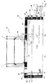
- FIG. 3 shows the lock system 22 in a side view.
- the filling side 42 is located on the left in the drawing. That is, the wheel loader moves from the left and tilts the substrate with the blade in the left open hopper 40. The substrate slips on the sloping walls of the hopper 40 on the second grid 38 and falls into the second chamber 30 on the closed second slide 36th It is conceivable to seal the second slide 36 with respect to the first chamber 28 with a barrier liquid, a simpler solution, however, is a rubber seal of the second slide 36. If, after filling one or more blade loads, a desired weight is reached, the, as weighing plate executed, second slider 36 from the first hydraulic cylinder 52 to the rear, in FIG. 3 right, pulled.
- the guide of the second slider 36 may be effected by means of slide rails (not shown) or the like.
- a heating device is optionally provided.
- a covered basin 56 is arranged below the first slide 32 in the open position.
- the basin 56 is designed in its dimensions so that the opened first slider 32 just covers it.
- Odors which pass from the container interior 34 into the first chamber 28 when the first slide 32 is open, are optionally aspirated through an opening 57 into a biofilter (not shown).
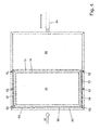
- FIG. 4 shows in a plan view the filling opening 24.
- an arrow is arranged in the drawing on the left, which marks the filling side 42.
- the second hydraulic cylinder 54 is outlined.
- the filling opening 24, covered gutters 58 connected to one another are arranged on three sides.
- the grooves 58 are in hydraulic communication with the basin 56. This ensures that the same level of liquid is established in the basin 56 and in the three channels 58.
- the liquid level is monitored by a probe (not shown).
- the basin 56 has a heater (not shown), which protects the barrier fluid from freezing.
- first slider 32 covers in the closed position, the three grooves 58 and one of the filling side 42 nearest part of the water basin 56. In its open position, the first slide 32 covers the basin 56 completely. Above the basin 56 and the first slide 32, a scraper 61 is arranged on a longitudinal side 59 of the first slide 32 facing away from the filling side 42. The scraper 61 covers the entire longitudinal side 59 of the first slider 32 and serves to scrape any organic substances resting on the first slider 32 when the first slider 32 is opened into the throw-in opening 24.
- rollers 62 are arranged laterally on the first slide 32, in the drawing above and below.
- the rollers 62 roll in addition to the lateral grooves 58 and thus ensure the safe opening and closing of the first slide 32nd
- FIG. 5 Shown is a section through a lateral channel 58.
- the channel 58 is covered by the closed first slide 32.
- a cover 63 arranged above the channel 58 protects the barrier liquid standing in the channel 58 when the first slide 32 is closed, against contamination, and seals the entire basin 56 upwards.
- the roller 62 is disposed adjacent to the channel in a rail which may have a U-shaped cross-section such that a tread 64 rolls over the rail.
- the roller 62 is mounted on a tab 68, which is arranged on a lower side 70 of the first lid 32.
- a web 72 protrudes from above into the channel 58.
- the web 72 is attached gas-tight from below to the first slider 32 by welding, gluing, riveting or similar methods.
- An extension of the web 72 that is perpendicular to the first slide 32 is dimensioned such that it protrudes below the liquid level 74 in the groove 58, but does not bear against the groove bottom 66.
- the cross section of the channel 58 is 100 mm wide and 120 mm high, the extension of the web perpendicular to the first slider 32 is 130 mm.
- the web 72 extends over the entire length of the first slider 32nd
- the upper and lower sides of the first slider 32 are provided with a web 72.
- a third side 76 of the first slider facing away from the filling side 42 is provided with a third web 78.
- the lateral webs 72 are gas-tightly connected to the third web 78 at their ends. This way are three sides of the first Slider 32 sealed against the container interior 34.
- An embodiment of a sealing of an arranged on the filling side 42 of the lock system end face 80 of the first slider 32 is in FIG. 6 shown.
- FIG. 6 shows in cross section the channel 58 which is arranged parallel to the filling side 42.
- a float 82 Arranged in the channel 58 is a float 82.
- the float 82 has an, for example, circular cross-section. But there are also other cross-sectional shapes conceivable. Its extent along the groove 58 is dimensioned such that it bears against the webs 72 with both ends closed when the first slide 32 is closed.
- Float 82 floats on the liquid in gutter 58 such that an uppermost point protrudes above liquid level 74 so far that float 80 is forced into the liquid by closing first spool 32.
- the buoyancy force pushes the float 82 with the uppermost point 84 against the underside 70 of the first slider 32, thus sealing it against the container interior 34.
- a simpler possibility (not shown) to seal the end face of the first slide represents the arrangement of a large-volume rubber seal between end face 80 and filling 42.
- a sealing effect is achieved by the contact pressure with which the second hydraulic cylinder 54 presses the first slide against the rubber seal ,
- FIG. 7 shows, for example, a mashing tank 86, equipped with the lock system 22.
- the mash tank 86 shown is usually formed as a cylindrical hollow body, which has, for example, a diameter of 4 m and a depth of 2 m. With a capacity of 12.5 m 3 is a filling level 88 of the mash tank at about half the depth.
- a container cover 90 the insertion opening 24, an inspection opening 92 and an air extraction 94 are arranged. Via the air extraction odors arising in the interior of the container are extracted by means of a blower and strongly diluted with ambient air or decomposed in a downstream biofilter.
- a pumping line 98 is provided.
- the recirculation line branches off from a sampling line 100.
- the extraction line 100 is arranged about 0.5 m above a bottom 102 of the container 18.
- a removal pump 104 is arranged in the withdrawal line 100. The removal pump 104 sucks the substrate from the container interior 34 and conveys it either further into the fermenter 10 or via the pumping line 98 back into the container 18. Thus, a thorough mixing of the substrate is achieved.
- the umpunpttechnisch can also be extended until under the throw-in edge of the lock and at the end with an obliquely downwards, best aligned in the direction of rotation of the container, nozzle 113 are equipped.
- the parallel stirring system 96 and 115 can be significantly increased.
- the stirring system 115 may be equipped with preferably horizontal wings 115, which may extend into the insertion opening 24.
- the nozzle 113 can also be optionally or additionally mounted laterally on the container wall in the region of the solids throw as diagonally as possible in the direction of rotation 116 of the container. It is also possible to install the nozzle 113 in an adjustable in spray angle design and equip with removable different sized spray heads.
- the dilution fluid supply can also be from another Containers, eg repository containers, via an extra pump. The amount is controlled via a flow meter 117.
- the start time can be coupled with the weighing system of the lock and only after a few tons of solids, as the mash fluid begins to thicken, take place. It is also possible that with each opening of the first slide 32, a certain amount of dilution liquid is automatically supplied.
- a sight glass 103 is arranged in a container wall.
- the sight glass can be equipped with a camera that transmits images from the container interior 34 to a screen.
- a first probe 108 is arranged in an upper container area, which detects overfilling of the container 18.
- a second probe 110 can be arranged in a lower container region, which detects the reaching of a minimum fill level, or reports the current fill level to the controller.
- the mash tank 86 shown operates as follows: While the wheel loader to be filled brings organic substances, the Anmaisch constitutioner 86 is filled up to the level of 88, so to about half, with liquid from digestate or fresh manure. The filling takes place via a separate line 112 and is monitored by a flow meter. It goes without saying that a high-performance pump is used for the filling, so that long waiting times for the wheel loader driver are avoided.
- the agitator 94 or 115 and / or the removal pump with the pumped circulation line 98 open are in operation.
- the organic substances fall through the lock system, as already described above, in the Anmaisch mater 86 and are mixed by the stirrers 94/115 and / or pumping the container contents with the liquid. Whether the agitator 94 is needed depends on the type of organics that are introduced or on a desired time, which requires mixing the organics with liquid.
- a removal of the substrate from the Anmaisch knowner 86 via the removal pump 104 A start of the removal pump 104 and a closing of the pumping line 98 or opening the sampling line 100 via a flow meter 117 and a timer, which is set according to an empirical value.
- the removal pump 104 3 minutes after closing the first slider 32, start.
- a small mash tank 86 the entire contents, except for the container sump 106, are fed to the fermenter 10 in one step.
- the removal pump 104 For example, by remote control, manually or after a pre-definable number of openings of the first slider 32 are started.
- the substrate In contrast to the mashing tank 86, the substrate remains in the container 18 for a relatively long time in the case of a larger hydrolysis tank and is then conveyed into the fermenter 10 at regular intervals, for example every two hours.
- Hydrolysis tanks have, for example, a filling volume of 200 m 3 . This usually requires more than one agitator.
- the number of agitators depends on the container size and the feed components used.
- a constant minimum level of about 50% -90% can be kept in the container 18. This allows the acidification of the substrate at a pH between 4.5 to 7.
Landscapes
- Health & Medical Sciences (AREA)
- Life Sciences & Earth Sciences (AREA)
- Chemical & Material Sciences (AREA)
- Engineering & Computer Science (AREA)
- Wood Science & Technology (AREA)
- Organic Chemistry (AREA)
- Bioinformatics & Cheminformatics (AREA)
- Zoology (AREA)
- Genetics & Genomics (AREA)
- Biochemistry (AREA)
- Microbiology (AREA)
- Biotechnology (AREA)
- General Engineering & Computer Science (AREA)
- General Health & Medical Sciences (AREA)
- Biomedical Technology (AREA)
- Sustainable Development (AREA)
- Molecular Biology (AREA)
- Clinical Laboratory Science (AREA)
- Analytical Chemistry (AREA)
- Oil, Petroleum & Natural Gas (AREA)
- General Chemical & Material Sciences (AREA)
- Treatment Of Sludge (AREA)
- Processing Of Solid Wastes (AREA)
- Fertilizers (AREA)
Applications Claiming Priority (1)
| Application Number | Priority Date | Filing Date | Title |
|---|---|---|---|
| DE102011081286A DE102011081286A1 (de) | 2011-08-19 | 2011-08-19 | Behälter zur Vorbehandlung organischer Stoffe |
Publications (2)
| Publication Number | Publication Date |
|---|---|
| EP2559751A1 true EP2559751A1 (fr) | 2013-02-20 |
| EP2559751B1 EP2559751B1 (fr) | 2016-05-18 |
Family
ID=47002587
Family Applications (1)
| Application Number | Title | Priority Date | Filing Date |
|---|---|---|---|
| EP12180162.5A Not-in-force EP2559751B1 (fr) | 2011-08-19 | 2012-08-10 | Récipient destiné au prétraitement de matières organiques |
Country Status (2)
| Country | Link |
|---|---|
| EP (1) | EP2559751B1 (fr) |
| DE (1) | DE102011081286A1 (fr) |
Families Citing this family (1)
| Publication number | Priority date | Publication date | Assignee | Title |
|---|---|---|---|---|
| CN113692971B (zh) * | 2021-08-03 | 2023-02-28 | 安徽水部落环保科技有限公司 | 一种基于沼液净化的蔬菜种植系统 |
Citations (9)
| Publication number | Priority date | Publication date | Assignee | Title |
|---|---|---|---|---|
| GB621772A (en) * | 1941-06-05 | 1949-04-19 | Gilbert Leon Rene Ducellier | Improvements in or relating to gasometer vessels for the methane fermentation of manures and other like materials |
| DE1063516B (de) * | 1952-04-05 | 1959-08-13 | Beckenbach Karl | Beschickungs- oder Entleerungs-vorrichtung fuer Schachtoefen |
| DE3610422A1 (de) * | 1986-03-27 | 1987-10-01 | Seebeck Technoproduct Gmbh | Vorkammer fuer oefen zur verbrennung von abfaellen |
| EP0530797A1 (fr) * | 1991-09-06 | 1993-03-10 | Pfister GmbH | Dispositif pour le dosage de matériaux en vrac |
| DE19621914C1 (de) * | 1996-05-31 | 1997-08-07 | Uts Umwelt Technik Sued Gmbh | Fermenter |
| WO2006089766A1 (fr) * | 2005-02-24 | 2006-08-31 | Christian Widmer | Procede et reacteur de traitement biologique de dechets organiques |
| DE102006047828A1 (de) * | 2006-10-10 | 2008-04-17 | Brauer, Kathrin | Kontinuierlicher Trockenfermenter |
| EP2177280A2 (fr) * | 2008-10-16 | 2010-04-21 | Hermann Dauser | Procédé et dispositif d'hydrolyse discontinue de substrats organiques |
| DE202009015199U1 (de) * | 2009-11-07 | 2010-04-29 | Röhren- und Pumpenwerk Bauer GmbH | Schleusenartiger Behälter zur Beschickung eines Biogas-Fermenter |
-
2011
- 2011-08-19 DE DE102011081286A patent/DE102011081286A1/de not_active Withdrawn
-
2012
- 2012-08-10 EP EP12180162.5A patent/EP2559751B1/fr not_active Not-in-force
Patent Citations (9)
| Publication number | Priority date | Publication date | Assignee | Title |
|---|---|---|---|---|
| GB621772A (en) * | 1941-06-05 | 1949-04-19 | Gilbert Leon Rene Ducellier | Improvements in or relating to gasometer vessels for the methane fermentation of manures and other like materials |
| DE1063516B (de) * | 1952-04-05 | 1959-08-13 | Beckenbach Karl | Beschickungs- oder Entleerungs-vorrichtung fuer Schachtoefen |
| DE3610422A1 (de) * | 1986-03-27 | 1987-10-01 | Seebeck Technoproduct Gmbh | Vorkammer fuer oefen zur verbrennung von abfaellen |
| EP0530797A1 (fr) * | 1991-09-06 | 1993-03-10 | Pfister GmbH | Dispositif pour le dosage de matériaux en vrac |
| DE19621914C1 (de) * | 1996-05-31 | 1997-08-07 | Uts Umwelt Technik Sued Gmbh | Fermenter |
| WO2006089766A1 (fr) * | 2005-02-24 | 2006-08-31 | Christian Widmer | Procede et reacteur de traitement biologique de dechets organiques |
| DE102006047828A1 (de) * | 2006-10-10 | 2008-04-17 | Brauer, Kathrin | Kontinuierlicher Trockenfermenter |
| EP2177280A2 (fr) * | 2008-10-16 | 2010-04-21 | Hermann Dauser | Procédé et dispositif d'hydrolyse discontinue de substrats organiques |
| DE202009015199U1 (de) * | 2009-11-07 | 2010-04-29 | Röhren- und Pumpenwerk Bauer GmbH | Schleusenartiger Behälter zur Beschickung eines Biogas-Fermenter |
Also Published As
| Publication number | Publication date |
|---|---|
| DE102011081286A1 (de) | 2013-02-21 |
| EP2559751B1 (fr) | 2016-05-18 |
Similar Documents
| Publication | Publication Date | Title |
|---|---|---|
| EP1251165B1 (fr) | Appareil pour le dosage de biomasse à un fermenteur faisant part d'une installation de biogaz | |
| EP1987128A1 (fr) | Bioréacteur pour la méthanisation de biomasse à teneur en solides élevée | |
| DE2944584C2 (de) | Vorrichtung zur Herstellung von Biogas | |
| DE2535756A1 (de) | Behaelter mit vorrichtungen zur erzeugung von methangas und aus organischen abfaellen | |
| EP2351824A1 (fr) | Dispositif et procédé destinés à la production de biogaz à partir de matières organiques | |
| DE202013100415U1 (de) | Gasbehälter, insbesondere zur Aufnahme von Biogas | |
| DE3881330T2 (de) | Vorrichtung zum entleeren und befuellen eines als extraktionsgefaess fuer eine durchlaufextraktionseinheit fuer pflanzenmaterial benutzbaren geschlossenen gefaesses und dasselbe verwendendes verfahren. | |
| AT11640U1 (de) | Vorrichtung zur gärgutbeschickung einer gäranlage | |
| DE102005057978A1 (de) | Fermentationseinrichtung mit gekoppeltem Substrat- und Sedimenttransport und Verfahren zum Betrieb der Fermentationseinrichtung | |
| WO2008099227A1 (fr) | Procédé et dispositif de production de biogaz à partir de biomasse | |
| EP2554638B1 (fr) | Procédé et dispositif de traitement mécanique ou mécanique-biologique des déchets | |
| DE202008010638U1 (de) | Rührwerk mit Einbringsystem für Feststoffe | |
| EP2559751B1 (fr) | Récipient destiné au prétraitement de matières organiques | |
| DE202006013772U1 (de) | Anlage zur Erzeugung von Biogas | |
| EP1717306B1 (fr) | Procédé et installation de production de biogaz par fermentation en millieu solide | |
| EP1170357B1 (fr) | Dispositif d'alimentation en matières solides pour un fermenteur d'une installation de production de biogaz | |
| EP0033724A2 (fr) | Fermenteur pour la fermentation anaérobie de substances putrescibles | |
| EP1072574B1 (fr) | Installation de fermentation avec un dispositif de deshydratation des produits de fermentation | |
| DE102014011315A1 (de) | Flüssigsubstratbehälter für eine Biogasanlage | |
| EP2465918B1 (fr) | Fermenteur sec de biomasse doté d'une alimentation et d'une extraction en continu | |
| DE102006024081A1 (de) | Verfahren zur Biogaserzeugung und Gärbehälter dafür | |
| WO2011107399A2 (fr) | Cuve avec mélangeur | |
| DE20308930U1 (de) | Biogasanlage | |
| CH657150A5 (en) | Biogas reactor | |
| DE202013003199U1 (de) | Vorrichtung zur mechanischen oder mechanisch-biologischen Behandlung von Abfällen |
Legal Events
| Date | Code | Title | Description |
|---|---|---|---|
| PUAI | Public reference made under article 153(3) epc to a published international application that has entered the european phase |
Free format text: ORIGINAL CODE: 0009012 |
|
| AK | Designated contracting states |
Kind code of ref document: A1 Designated state(s): AL AT BE BG CH CY CZ DE DK EE ES FI FR GB GR HR HU IE IS IT LI LT LU LV MC MK MT NL NO PL PT RO RS SE SI SK SM TR |
|
| AX | Request for extension of the european patent |
Extension state: BA ME |
|
| 17P | Request for examination filed |
Effective date: 20130819 |
|
| RBV | Designated contracting states (corrected) |
Designated state(s): AL AT BE BG CH CY CZ DE DK EE ES FI FR GB GR HR HU IE IS IT LI LT LU LV MC MK MT NL NO PL PT RO RS SE SI SK SM TR |
|
| REG | Reference to a national code |
Ref country code: DE Ref legal event code: R079 Ref document number: 502012007112 Country of ref document: DE Free format text: PREVIOUS MAIN CLASS: C12M0001107000 Ipc: C12M0001000000 |
|
| GRAP | Despatch of communication of intention to grant a patent |
Free format text: ORIGINAL CODE: EPIDOSNIGR1 |
|
| INTG | Intention to grant announced |
Effective date: 20151211 |
|
| RIC1 | Information provided on ipc code assigned before grant |
Ipc: C12M 1/34 20060101ALI20151127BHEP Ipc: C12M 1/26 20060101ALI20151127BHEP Ipc: C12M 1/00 20060101AFI20151127BHEP Ipc: C12M 1/18 20060101ALI20151127BHEP Ipc: C12M 1/107 20060101ALI20151127BHEP |
|
| GRAS | Grant fee paid |
Free format text: ORIGINAL CODE: EPIDOSNIGR3 |
|
| GRAA | (expected) grant |
Free format text: ORIGINAL CODE: 0009210 |
|
| AK | Designated contracting states |
Kind code of ref document: B1 Designated state(s): AL AT BE BG CH CY CZ DE DK EE ES FI FR GB GR HR HU IE IS IT LI LT LU LV MC MK MT NL NO PL PT RO RS SE SI SK SM TR |
|
| REG | Reference to a national code |
Ref country code: GB Ref legal event code: FG4D Free format text: NOT ENGLISH |
|
| REG | Reference to a national code |
Ref country code: CH Ref legal event code: EP |
|
| REG | Reference to a national code |
Ref country code: IE Ref legal event code: FG4D Free format text: LANGUAGE OF EP DOCUMENT: GERMAN Ref country code: AT Ref legal event code: REF Ref document number: 800478 Country of ref document: AT Kind code of ref document: T Effective date: 20160615 |
|
| REG | Reference to a national code |
Ref country code: DE Ref legal event code: R096 Ref document number: 502012007112 Country of ref document: DE |
|
| REG | Reference to a national code |
Ref country code: NL Ref legal event code: MP Effective date: 20160518 |
|
| REG | Reference to a national code |
Ref country code: LT Ref legal event code: MG4D |
|
| REG | Reference to a national code |
Ref country code: FR Ref legal event code: PLFP Year of fee payment: 5 |
|
| PG25 | Lapsed in a contracting state [announced via postgrant information from national office to epo] |
Ref country code: FI Free format text: LAPSE BECAUSE OF FAILURE TO SUBMIT A TRANSLATION OF THE DESCRIPTION OR TO PAY THE FEE WITHIN THE PRESCRIBED TIME-LIMIT Effective date: 20160518 Ref country code: NL Free format text: LAPSE BECAUSE OF FAILURE TO SUBMIT A TRANSLATION OF THE DESCRIPTION OR TO PAY THE FEE WITHIN THE PRESCRIBED TIME-LIMIT Effective date: 20160518 Ref country code: LT Free format text: LAPSE BECAUSE OF FAILURE TO SUBMIT A TRANSLATION OF THE DESCRIPTION OR TO PAY THE FEE WITHIN THE PRESCRIBED TIME-LIMIT Effective date: 20160518 Ref country code: NO Free format text: LAPSE BECAUSE OF FAILURE TO SUBMIT A TRANSLATION OF THE DESCRIPTION OR TO PAY THE FEE WITHIN THE PRESCRIBED TIME-LIMIT Effective date: 20160818 |
|
| PG25 | Lapsed in a contracting state [announced via postgrant information from national office to epo] |
Ref country code: RS Free format text: LAPSE BECAUSE OF FAILURE TO SUBMIT A TRANSLATION OF THE DESCRIPTION OR TO PAY THE FEE WITHIN THE PRESCRIBED TIME-LIMIT Effective date: 20160518 Ref country code: GR Free format text: LAPSE BECAUSE OF FAILURE TO SUBMIT A TRANSLATION OF THE DESCRIPTION OR TO PAY THE FEE WITHIN THE PRESCRIBED TIME-LIMIT Effective date: 20160819 Ref country code: ES Free format text: LAPSE BECAUSE OF FAILURE TO SUBMIT A TRANSLATION OF THE DESCRIPTION OR TO PAY THE FEE WITHIN THE PRESCRIBED TIME-LIMIT Effective date: 20160518 Ref country code: HR Free format text: LAPSE BECAUSE OF FAILURE TO SUBMIT A TRANSLATION OF THE DESCRIPTION OR TO PAY THE FEE WITHIN THE PRESCRIBED TIME-LIMIT Effective date: 20160518 Ref country code: PT Free format text: LAPSE BECAUSE OF FAILURE TO SUBMIT A TRANSLATION OF THE DESCRIPTION OR TO PAY THE FEE WITHIN THE PRESCRIBED TIME-LIMIT Effective date: 20160919 Ref country code: SE Free format text: LAPSE BECAUSE OF FAILURE TO SUBMIT A TRANSLATION OF THE DESCRIPTION OR TO PAY THE FEE WITHIN THE PRESCRIBED TIME-LIMIT Effective date: 20160518 Ref country code: LV Free format text: LAPSE BECAUSE OF FAILURE TO SUBMIT A TRANSLATION OF THE DESCRIPTION OR TO PAY THE FEE WITHIN THE PRESCRIBED TIME-LIMIT Effective date: 20160518 |
|
| PG25 | Lapsed in a contracting state [announced via postgrant information from national office to epo] |
Ref country code: IT Free format text: LAPSE BECAUSE OF FAILURE TO SUBMIT A TRANSLATION OF THE DESCRIPTION OR TO PAY THE FEE WITHIN THE PRESCRIBED TIME-LIMIT Effective date: 20160518 Ref country code: BE Free format text: LAPSE BECAUSE OF NON-PAYMENT OF DUE FEES Effective date: 20160831 |
|
| PG25 | Lapsed in a contracting state [announced via postgrant information from national office to epo] |
Ref country code: CZ Free format text: LAPSE BECAUSE OF FAILURE TO SUBMIT A TRANSLATION OF THE DESCRIPTION OR TO PAY THE FEE WITHIN THE PRESCRIBED TIME-LIMIT Effective date: 20160518 Ref country code: SK Free format text: LAPSE BECAUSE OF FAILURE TO SUBMIT A TRANSLATION OF THE DESCRIPTION OR TO PAY THE FEE WITHIN THE PRESCRIBED TIME-LIMIT Effective date: 20160518 Ref country code: RO Free format text: LAPSE BECAUSE OF FAILURE TO SUBMIT A TRANSLATION OF THE DESCRIPTION OR TO PAY THE FEE WITHIN THE PRESCRIBED TIME-LIMIT Effective date: 20160518 Ref country code: EE Free format text: LAPSE BECAUSE OF FAILURE TO SUBMIT A TRANSLATION OF THE DESCRIPTION OR TO PAY THE FEE WITHIN THE PRESCRIBED TIME-LIMIT Effective date: 20160518 Ref country code: DK Free format text: LAPSE BECAUSE OF FAILURE TO SUBMIT A TRANSLATION OF THE DESCRIPTION OR TO PAY THE FEE WITHIN THE PRESCRIBED TIME-LIMIT Effective date: 20160518 |
|
| REG | Reference to a national code |
Ref country code: DE Ref legal event code: R097 Ref document number: 502012007112 Country of ref document: DE |
|
| PG25 | Lapsed in a contracting state [announced via postgrant information from national office to epo] |
Ref country code: PL Free format text: LAPSE BECAUSE OF FAILURE TO SUBMIT A TRANSLATION OF THE DESCRIPTION OR TO PAY THE FEE WITHIN THE PRESCRIBED TIME-LIMIT Effective date: 20160518 Ref country code: SM Free format text: LAPSE BECAUSE OF FAILURE TO SUBMIT A TRANSLATION OF THE DESCRIPTION OR TO PAY THE FEE WITHIN THE PRESCRIBED TIME-LIMIT Effective date: 20160518 |
|
| PLBE | No opposition filed within time limit |
Free format text: ORIGINAL CODE: 0009261 |
|
| STAA | Information on the status of an ep patent application or granted ep patent |
Free format text: STATUS: NO OPPOSITION FILED WITHIN TIME LIMIT |
|
| PG25 | Lapsed in a contracting state [announced via postgrant information from national office to epo] |
Ref country code: MC Free format text: LAPSE BECAUSE OF FAILURE TO SUBMIT A TRANSLATION OF THE DESCRIPTION OR TO PAY THE FEE WITHIN THE PRESCRIBED TIME-LIMIT Effective date: 20160518 |
|
| REG | Reference to a national code |
Ref country code: CH Ref legal event code: PL |
|
| 26N | No opposition filed |
Effective date: 20170221 |
|
| PG25 | Lapsed in a contracting state [announced via postgrant information from national office to epo] |
Ref country code: LI Free format text: LAPSE BECAUSE OF NON-PAYMENT OF DUE FEES Effective date: 20160831 Ref country code: CH Free format text: LAPSE BECAUSE OF NON-PAYMENT OF DUE FEES Effective date: 20160831 |
|
| PG25 | Lapsed in a contracting state [announced via postgrant information from national office to epo] |
Ref country code: SI Free format text: LAPSE BECAUSE OF FAILURE TO SUBMIT A TRANSLATION OF THE DESCRIPTION OR TO PAY THE FEE WITHIN THE PRESCRIBED TIME-LIMIT Effective date: 20160518 |
|
| REG | Reference to a national code |
Ref country code: IE Ref legal event code: MM4A |
|
| PG25 | Lapsed in a contracting state [announced via postgrant information from national office to epo] |
Ref country code: IE Free format text: LAPSE BECAUSE OF NON-PAYMENT OF DUE FEES Effective date: 20160810 |
|
| REG | Reference to a national code |
Ref country code: FR Ref legal event code: PLFP Year of fee payment: 6 |
|
| PG25 | Lapsed in a contracting state [announced via postgrant information from national office to epo] |
Ref country code: LU Free format text: LAPSE BECAUSE OF NON-PAYMENT OF DUE FEES Effective date: 20160810 |
|
| PGFP | Annual fee paid to national office [announced via postgrant information from national office to epo] |
Ref country code: GB Payment date: 20170823 Year of fee payment: 6 |
|
| PG25 | Lapsed in a contracting state [announced via postgrant information from national office to epo] |
Ref country code: HU Free format text: LAPSE BECAUSE OF FAILURE TO SUBMIT A TRANSLATION OF THE DESCRIPTION OR TO PAY THE FEE WITHIN THE PRESCRIBED TIME-LIMIT; INVALID AB INITIO Effective date: 20120810 Ref country code: CY Free format text: LAPSE BECAUSE OF FAILURE TO SUBMIT A TRANSLATION OF THE DESCRIPTION OR TO PAY THE FEE WITHIN THE PRESCRIBED TIME-LIMIT Effective date: 20160518 |
|
| PG25 | Lapsed in a contracting state [announced via postgrant information from national office to epo] |
Ref country code: MT Free format text: LAPSE BECAUSE OF FAILURE TO SUBMIT A TRANSLATION OF THE DESCRIPTION OR TO PAY THE FEE WITHIN THE PRESCRIBED TIME-LIMIT Effective date: 20160518 Ref country code: TR Free format text: LAPSE BECAUSE OF FAILURE TO SUBMIT A TRANSLATION OF THE DESCRIPTION OR TO PAY THE FEE WITHIN THE PRESCRIBED TIME-LIMIT Effective date: 20160518 Ref country code: MK Free format text: LAPSE BECAUSE OF FAILURE TO SUBMIT A TRANSLATION OF THE DESCRIPTION OR TO PAY THE FEE WITHIN THE PRESCRIBED TIME-LIMIT Effective date: 20160518 Ref country code: IS Free format text: LAPSE BECAUSE OF FAILURE TO SUBMIT A TRANSLATION OF THE DESCRIPTION OR TO PAY THE FEE WITHIN THE PRESCRIBED TIME-LIMIT Effective date: 20160518 |
|
| PG25 | Lapsed in a contracting state [announced via postgrant information from national office to epo] |
Ref country code: BG Free format text: LAPSE BECAUSE OF FAILURE TO SUBMIT A TRANSLATION OF THE DESCRIPTION OR TO PAY THE FEE WITHIN THE PRESCRIBED TIME-LIMIT Effective date: 20160518 |
|
| REG | Reference to a national code |
Ref country code: AT Ref legal event code: MM01 Ref document number: 800478 Country of ref document: AT Kind code of ref document: T Effective date: 20170810 |
|
| PG25 | Lapsed in a contracting state [announced via postgrant information from national office to epo] |
Ref country code: AL Free format text: LAPSE BECAUSE OF FAILURE TO SUBMIT A TRANSLATION OF THE DESCRIPTION OR TO PAY THE FEE WITHIN THE PRESCRIBED TIME-LIMIT Effective date: 20160518 |
|
| PG25 | Lapsed in a contracting state [announced via postgrant information from national office to epo] |
Ref country code: AT Free format text: LAPSE BECAUSE OF NON-PAYMENT OF DUE FEES Effective date: 20170810 |
|
| GBPC | Gb: european patent ceased through non-payment of renewal fee |
Effective date: 20180810 |
|
| PG25 | Lapsed in a contracting state [announced via postgrant information from national office to epo] |
Ref country code: GB Free format text: LAPSE BECAUSE OF NON-PAYMENT OF DUE FEES Effective date: 20180810 |
|
| PGFP | Annual fee paid to national office [announced via postgrant information from national office to epo] |
Ref country code: FR Payment date: 20190822 Year of fee payment: 8 |
|
| PG25 | Lapsed in a contracting state [announced via postgrant information from national office to epo] |
Ref country code: FR Free format text: LAPSE BECAUSE OF NON-PAYMENT OF DUE FEES Effective date: 20200831 |
|
| P01 | Opt-out of the competence of the unified patent court (upc) registered |
Effective date: 20230523 |
|
| PGFP | Annual fee paid to national office [announced via postgrant information from national office to epo] |
Ref country code: DE Payment date: 20231019 Year of fee payment: 12 |
|
| REG | Reference to a national code |
Ref country code: DE Ref legal event code: R119 Ref document number: 502012007112 Country of ref document: DE |
|
| PG25 | Lapsed in a contracting state [announced via postgrant information from national office to epo] |
Ref country code: DE Free format text: LAPSE BECAUSE OF NON-PAYMENT OF DUE FEES Effective date: 20250301 |