EP2559821A1 - Entrevous en matériau à faible densité - Google Patents
Entrevous en matériau à faible densité Download PDFInfo
- Publication number
- EP2559821A1 EP2559821A1 EP12178971A EP12178971A EP2559821A1 EP 2559821 A1 EP2559821 A1 EP 2559821A1 EP 12178971 A EP12178971 A EP 12178971A EP 12178971 A EP12178971 A EP 12178971A EP 2559821 A1 EP2559821 A1 EP 2559821A1
- Authority
- EP
- European Patent Office
- Prior art keywords
- interjoists
- stiffener
- spout
- polystyrene
- beams
- Prior art date
- Legal status (The legal status is an assumption and is not a legal conclusion. Google has not performed a legal analysis and makes no representation as to the accuracy of the status listed.)
- Granted
Links
Images
Classifications
-
- E—FIXED CONSTRUCTIONS
- E04—BUILDING
- E04B—GENERAL BUILDING CONSTRUCTIONS; WALLS, e.g. PARTITIONS; ROOFS; FLOORS; CEILINGS; INSULATION OR OTHER PROTECTION OF BUILDINGS
- E04B5/00—Floors; Floor construction with regard to insulation; Connections specially adapted therefor
- E04B5/16—Load-carrying floor structures wholly or partly cast or similarly formed in situ
- E04B5/17—Floor structures partly formed in situ
- E04B5/23—Floor structures partly formed in situ with stiffening ribs or other beam-like formations wholly or partly prefabricated
- E04B5/26—Floor structures partly formed in situ with stiffening ribs or other beam-like formations wholly or partly prefabricated with filling members between the beams
- E04B5/261—Monolithic filling members
- E04B5/265—Monolithic filling members with one or more hollow cores
-
- E—FIXED CONSTRUCTIONS
- E04—BUILDING
- E04B—GENERAL BUILDING CONSTRUCTIONS; WALLS, e.g. PARTITIONS; ROOFS; FLOORS; CEILINGS; INSULATION OR OTHER PROTECTION OF BUILDINGS
- E04B5/00—Floors; Floor construction with regard to insulation; Connections specially adapted therefor
- E04B5/16—Load-carrying floor structures wholly or partly cast or similarly formed in situ
- E04B5/17—Floor structures partly formed in situ
- E04B5/23—Floor structures partly formed in situ with stiffening ribs or other beam-like formations wholly or partly prefabricated
- E04B5/26—Floor structures partly formed in situ with stiffening ribs or other beam-like formations wholly or partly prefabricated with filling members between the beams
- E04B5/266—Filling members covering the undersurface of the beams
Definitions
- the invention relates to the field of building construction and more particularly to the construction of floors.
- the construction of a floor consists of initially installing parallel beams regularly spaced from each other, such as inverted T-section beams. Interjoists are then installed on these beams: each interjoists rests by its two longitudinal edges on two beams.
- slab compression When all the interjoists have been installed, they delimit together with the beams that carry them a surface intended to support a concrete slab, called slab compression.
- the concrete is poured from the compression slab which then covers the interjoists and beams and any reinforcement steels.
- Such interjoists which is known in particular from the patent application FR2829780 is made of polystyrene, so that it also participates in the thermal insulation offered by the floor that it constitutes with the slab of compression.
- Each longitudinal edge has a side face from which a spout which extends to protrude transversely from the rest of the interjoists body.
- the free space located above the spout defines the geometry of the keyway, which provides a connecting function between the compression slab and the beam.
- the applicable standards require that this keying has a minimum height of 4 cm in the case of prestressed beams.
- interjoists must not give way under the weight of an operator moving on the assembly formed by the beams and interjoists, during the phases prior to the casting of the compression slab.
- the applicable standards require that a interjoists in place be able to support a weight of 150 kilograms without yielding.
- the object of the invention is to provide a solution for reducing the thickness of the spoiler of a interstice polystyrene type or the like, without penalizing its mechanical strength.
- the subject of the invention is an interjoists comprising a body of low density material such as polystyrene and having two longitudinal edges each having a transversely protruding spout, said interjoists being intended to be installed on two beams of the inverted T-section type or the like, having a spout in abutment on each beam, characterized in that it comprises at least one stiffener material having a higher strength than the material of the interjoists body, this stiffener being arranged to increase the cohesion of a beak with the rest of the body of between you.
- the invention also relates to a interjoiset thus defined, comprising a stiffener in the form of a Z-section angle defining an upper portion, a middle portion and a lower portion, the upper portion covering a lower face of the nozzle.
- the invention also relates to a interjoiset thus defined, wherein the stiffener is molded with the polystyrene interjoists body, so that the lower portion of the stiffener is taken in the thickness of the polystyrene forming the interjoists body.
- the invention also relates to a interjoiset thus defined, wherein the stiffener has in its lower portion holes or openings through which its anchoring in the polystyrene forming the interjoists body is improved.
- each stiffener is made of a material such as plastic that can be cut with a hand saw tool.
- the invention also relates to a interjoiset thus defined, wherein the stiffener comprises ribs extending transversely, to strengthen the connection of the middle portion with the upper portion.
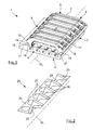
- the interjoists according to the invention which is identified by 1 in the figure 1 , comprises a polystyrene body 2 extending in a longitudinal direction DL. This body is delimited by an upper face 3, a lower face 4, a first longitudinal edge 6, a second longitudinal edge 7, a first transverse edge 8 and a second transverse edge 9.
- the faces 3 and 4 are respectively the upper and lower faces of the interjoists when it is in place on two beams, that is to say when it is oriented as in the figure 1 .
- the lower portion of this interjoists which is indicated by 11, has the general shape of a relatively thick parallelepipedal planar wall, which protrudes transversely well beyond the longitudinal edge 6.
- the longitudinal edge 6 has a generally vertical lateral face 12, of which extends transversely a spout 13 constituting a flange which extends over the entire length of the interjoists body 1.
- This spout 13 has a lower face 14 which extends the upper part of the lateral face 12, the lower portion of this lateral face 12 joining the lower portion 11 of the interjoists which protrudes beyond the longitudinal edge 12.
- the longitudinal edge 7 also has a substantially vertical lateral face 16, of which transversely extends a spout 17 which is situated at the level of the upper part of the vertical wall 16, this spout 17 having a lower face 18 which extends the upper part of the vertical wall 16.
- the underside 14 of the spout 13 bears on the edge of the heel of an inverted T-section beam
- the lower face 18 of the spout 17 bears on the heel of a spider. other inverted T-section beam.
- the interjoists comprise a polystyrene body provided with stiffeners which reinforce the cohesion of each spout with the rest of the polystyrene body.
- the interjoists according to the invention comprises a first stiffener 19 reinforcing the mechanical strength of the spout 13, and a second stiffener 21 reinforcing the mechanical strength of the second spout 17.
- stiffeners 19 and 21 here extend in the mass of the polystyrene interjoists body: their integration is ensured by putting them in place in the mold for manufacturing the polystyrene body, before injection and constitution of the expanded polystyrene in this mold. .
- the body of interjoists is molded around the stiffeners.
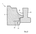
- the stiffener 21 is in the form of an angle having in cross section a shape corresponding to that of the letter Z. It comprises a medial portion 22, in the form of a generally flat rectangular wall, extended in the upper part by a portion superior 23 in form she also a rectangular wall, and extended in its lower part by a lower portion 24 in form also a generally rectangular wall.
- this stiffener or stiffener 21 also comprises a plurality of ribs 26 each extending in a plane oriented transversely to the longitudinal direction DL, and each joining the middle portion 22 with the upper portion 23 to increase the mechanical strength of the connection between these two portions.
- These ribs 26 are distributed along the stiffener 21 so as to be evenly distributed along the longitudinal direction DL, that is to say along the edge 25 corresponding to the junction of the middle portion 22 with the portion superior 23.
- the ribs 26 protrude from the outer faces of the portion 22 and the portion 23, that is to say they exceed the convex shape that jointly delimit these two generally planar portions.
- each rib 26 may extend to the lower portion 24, so as to also stiffen the mechanical connection joining the middle portion 22 and the lower portion 24.
- Other forms of ribs are possible to stiffen the connection of the middle portion 22 at the upper portion 23 and the lower portion 24.
- the lower portion 24 advantageously comprises different holes 27 uniformly distributed over its entire length, which significantly improve the setting of the stiffener in the mass of polystyrene constituting the interjoists body.
- the fact that the lower portions are firmly anchored in the mass of polystyrene forming the interjoin body 1 can significantly improve the mechanical strength of this interjoists.
- holes may also be provided in particular at the middle portion 22, in order to further increase the mechanical quality of the anchoring of the stiffener in the polystyrene mass of the interjoists body, in order to increase still significantly the mechanical strength of the whole.
- stiffeners 19 and 21 have substantially the same shapes, and they are arranged symmetrically in the interjoists body, so as to stiffen the spouts 13 and 17 which have opposite orientations relative to the longitudinal direction DL.
- stiffeners 19 and 21 make it possible to significantly increase the mechanical strength of the interjoists by stiffening the junction of each spout 19, 21 with the remainder of the polystyrene interjoists body.
- the stiffener 19 makes it possible to reinforce the edge corresponding to the junction of the lateral face 12 with the lower face of the nose 14, which makes it possible to avoid the appearance in this region of a rupture primer when the interjoists is solicited by the application of a large load.
- the interjoists 21 is arranged to reinforce the edge corresponding to the junction of the lateral face 16 with the lower face 18 of the spout 17 in order to avoid the appearance of a rupture primer in this zone.
- the stiffener 21 is positioned in the mass of the interjoists body so that its lower portion 24 is completely embedded in the thickness of the body of interjoists, and that its median portion is also embedded in this polystyrene while skirting the lateral face 12.
- the stiffener 21 is implanted in a similar manner in the interjoists body.
- stiffeners 19 and 21 are also advantageously made of a material of course with a higher mechanical strength than polystyrene, but can still be cut with a tool usually available on site, such as a handsaw.
Landscapes
- Engineering & Computer Science (AREA)
- Architecture (AREA)
- Physics & Mathematics (AREA)
- Electromagnetism (AREA)
- Civil Engineering (AREA)
- Structural Engineering (AREA)
- Laminated Bodies (AREA)
- Moulds For Moulding Plastics Or The Like (AREA)
- Body Structure For Vehicles (AREA)
Abstract
Description
- L'invention concerne le domaine de la construction de bâtiments et plus particulièrement de la construction de planchers.
- La construction d'un plancher consiste à installer dans un premier temps des poutrelles parallèles régulièrement espacées les unes des autres, telles que des poutrelles à section en T inversé. Des entrevous sont ensuite installés sur ces poutrelles : chaque entrevous repose par ses deux bords longitudinaux sur deux poutrelles.
- Lorsque tous les entrevous ont été installés, ils délimitent conjointement avec les poutrelles qui les portent une surface destinée à supporter une dalle de béton, appelée dalle de compression.
- Avant de procéder au coulage de cette dalle de compression, différents opérateurs doivent marcher sur l'assemblage que constituent les entrevous et les poutrelles qui les portent, par exemple pour installer des treillis d'aciers soudés destinés à renforcer le plancher.
- Une fois que ces opérations de préparation sont terminées, on procède au coulage du béton de la dalle de compression qui vient alors recouvrir les entrevous et les poutrelles ainsi que les éventuels aciers de renforcement.
- Un tel entrevous, qui est connu notamment de la demande de brevet
FR2829780 - Comme le montrent les figures de ce document
FR2829780 - Chaque bord longitudinal comporte une face latérale dont part un bec qui s'étend pour dépasser transversalement du reste du corps d'entrevous. Lorsque l'entrevous est en place, l'un de ses bords est en appui sur une première poutrelle par son bec, et l'autre bord est en appui sur l'autre poutrelle par l'autre bec qu'il délimite.
- Une fois l'entrevous mis en place, l'espace libre situé au dessus du bec définit la géométrie du clavetage, qui assure une fonction de liaison entre la dalle de compression et la poutrelle. Les normes applicables imposent que ce clavetage ait une hauteur minimale de 4 cm dans le cas de poutrelles précontraintes.
- Une fois en place, un tel entrevous ne doit pas céder sous le poids d'un opérateur se déplaçant sur l'ensemble constitué par les poutrelles et les entrevous, durant les phases préalables au coulage de la dalle de compression. Concrètement, les normes applicables imposent qu'un entrevous en place soit capable de supporter un poids de 150 kilogrammes sans céder.
- Lorsque l'entrevous est fabriqué en polystyrène, cette contrainte de tenue mécanique se traduit par une épaisseur importante du bec, qui à son tour induit une hauteur minimale de la poutrelle pour respecter la hauteur minimale du clavetage, ce qui est pénalisant en matière de poids de la poutrelle.
- Le but de l'invention est de proposer une solution pour réduire l'épaisseur du becquet d'un entrevous du type en polystyrène ou analogue, sans pénaliser sa tenue mécanique.
- A cet effet, l'invention a pour objet un entrevous comprenant un corps en matériau à faible densité tel que du polystyrène et ayant deux bords longitudinaux comportant chacun un bec dépassant transversalement, cet entrevous étant destiné à être installé sur deux poutrelles du type à section en T inversé ou analogue, en ayant un bec en appui sur chaque poutrelle, caractérisé en ce qu'il comporte au moins un rigidificateur en matériau ayant une plus haute résistance que le matériau du corps d'entrevous, ce rigidificateur étant agencé pour augmenter la cohésion d'un bec avec le reste du corps d'entrevous.
- Avec cette solution, la résistance de chaque bec est accrue, ce qui permet d'en réduire l'épaisseur, et par là même, de réduire la hauteur de la poutrelle.
- L'invention concerne également un entrevous ainsi défini, comprenant un rigidificateur sous forme d'une cornière à section en Z délimitant une portion supérieure, une portion médiane et une portion inférieure, la portion supérieure recouvrant une face inférieure du bec.
- L'invention concerne également un entrevous ainsi défini, dans lequel le rigidificateur est moulé avec le polystyrène du corps d'entrevous, de telle manière que la portion inférieure du rigidificateur est prise dans l'épaisseur du polystyrène formant le corps d'entrevous.
- L'invention concerne également un entrevous ainsi défini, dans lequel le rigidificateur comporte dans sa portion inférieure des trous ou ouvertures par lesquels son ancrage dans le polystyrène formant le corps d'entrevous est amélioré.
- L'invention concerne également un entrevous ainsi défini, dans lequel chaque rigidificateur est fabriqué dans un matériau tel que du plastique pouvant être coupé avec un outil de type scie égoïne.
- L'invention concerne également un entrevous ainsi défini, dans lequel le rigidificateur comporte des nervures s'étendant transversalement, pour renforcer la liaison de la portion médiane avec la portion supérieure.
-
- La
figure 1 est une vue en perspective de l'entrevous selon l'invention ; - La
figure 2 est une vue en perspective du rigidificateur de l'entrevous selon l'invention ; - La
figure 3 est une vue en coupe tranversale de l'entrevous selon l'invention. - L'entrevous selon l'invention qui est repéré par 1 dans la
figure 1 , comporte un corps 2 en polystyrène s'étendant selon une direction longitudinale DL. Ce corps est délimité par une face supérieure 3, une face inférieure 4, un premier bord longitudinal 6, un second bord longitudinal 7, un premier bord transversal 8 et un second bord transversal 9. - Comme on l'aura compris, les faces 3 et 4 sont respectivement les faces supérieure et inférieure de l'entrevous lorsque celui-ci est en place sur deux poutrelles, c'est-à-dire lorsqu'il est orienté comme dans la
figure 1 . - La portion inférieure de cet entrevous qui est repérée par 11 a une forme générale de paroi plane parallélépipédique relativement épaisse, qui dépasse transversalement bien au delà du bord longitudinal 6. Lorsque tous les entrevous d'un plancher sont en place, ils délimitent conjointement, par la réunion de leurs portions inférieures 11, une face plane recouvrant les faces inférieures des poutrelles.
- Comme visible dans la
figure 1 , le bord longitudinal 6 comporte une face latérale 12 généralement verticale, dont dépasse transversalement un bec 13 constituant un rebord qui s'étend sur toute la longueur du corps d'entrevous 1. Ce bec 13 comporte une face inférieure 14 qui prolonge la partie haute de la face latérale 12, la portion inférieure de cette face latérale 12 rejoignant quant à elle la portion inférieure 11 de l'entrevous qui dépasse au delà du bord longitudinal 12. - De manière analogue, le bord longitudinal 7 comporte lui aussi une face latérale 16 sensiblement verticale, dont dépasse transversalement un bec 17 qui est situé au niveau de la partie haute de la paroi verticale 16, ce bec 17 comportant une face inférieure 18 qui prolonge la partie haute de la paroi verticale 16.
- Lorsque l'entrevous est en place, la face inférieure 14 du bec 13 est en appui sur le bord du talon d'une poutrelle à section en T inversé, et la face inférieure 18 du bec 17 est en appui sur le talon d'une autre poutrelle à section en T inversé.
- Selon l'invention, l'entrevous comporte un corps en polystyrène pourvu de rigidificateurs qui renforcent la cohésion de chaque bec avec le reste du corps en polystyrène. Dans l'exemple des figures, l'entrevous selon l'invention comporte un premier rigidificateur 19 renforçant la tenue mécanique du bec 13, et un second rigidificateur 21 renforçant la tenue mécanique du second bec 17.
- Ces deux rigidificateurs 19 et 21 s'étendent ici dans la masse du corps d'entrevous en polystyrène : leur intégration est assurée en les mettant en place dans le moule de fabrication du corps en polystyrène, avant injection et constitution du polystyrène expansé dans ce moule. Le corps d'entrevous est ainsi surmoulé autour des rigidificateurs.
- Comme visible dans la
figure 2 , le rigidificateur 21 se présente sous forme d'une cornière ayant en section transversale une forme correspondant à celle de la lettre Z. Il comporte une portion médiane 22, sous forme d'une paroi rectangulaire généralement plane, prolongée en partie haute par une portion supérieure 23 sous forme elle aussi d'une paroi rectangulaire, et prolongée dans sa partie basse par une portion inférieure 24 sous forme elle aussi d'une paroi généralement rectangulaire. - Complémentairement, ce rigidificateur ou raidisseur 21 comporte encore plusieurs nervures 26 s'étendant chacune selon un plan orienté transversalement par rapport à la direction longitudinale DL, et réunissant chacune la portion médiane 22 avec la portion supérieure 23 pour accroître la tenue mécanique de la liaison réunissant ces deux portions.
- Ces nervures 26 sont distribuées le long du rigidificateur 21 de manière à être régulièrement réparties le long de la direction longitudinale DL, c'est-à-dire le long de l'arête 25 correspondant à la jonction de la portion médiane 22 avec la portion supérieure 23.
- Comme visible plus clairement dans la
figure 2 , les nervures 26 dépassent des faces externes de la portion 22 et de la portion 23, c'est-à-dire qu'elles dépassent de la forme convexe que délimitent conjointement ces deux portions généralement planes. - Complémentairement, chaque nervure 26 peut s'étendre jusqu'à la portion inférieure 24, de manière à également rigidifier la liaison mécanique réunissant la portion médiane 22 et la portion inférieure 24. D'autres formes de nervures sont envisageables pour rigidifier la liaison de la partie médiane 22 à la portion supérieure 23 et à la portion inférieure 24.
- La portion inférieure 24 comporte avantageusement différents trous 27 uniformément répartis sur toute sa longueur, qui permettent d'améliorer significativement la prise du rigidificateur dans la masse de polystyrène constituant le corps d'entrevous. En particulier, il apparaît que lorsque l'entrevous est sollicité mécaniquement par un opérateur marchant à sa face supérieure, le fait que les portions inférieures soient fermement ancrées dans la masse du polystyrène formant le corps d'entrevous 1 permet d'améliorer significativement la tenue mécanique de cet entrevous.
- Par ailleurs, d'autres trous peuvent également être prévus notamment au niveau de la portion médiane 22, afin d'accroître encore la qualité mécanique de l'ancrage du rigidificateur dans la masse de polystyrène du corps d'entrevous, en vue d'accroître encore significativement la tenue mécanique de l'ensemble.
- Comme on l'a compris, les rigidificateurs 19 et 21 ont sensiblement les mêmes formes, et ils sont disposés de manière symétrique dans le corps d'entrevous, de manière à rigidifier les becs 13 et 17 qui ont des orientations opposées par rapport à la direction longitudinale DL.
- Comme on l'aura compris, les rigidificateurs 19 et 21 permettent d'augmenter significativement la tenue mécanique de l'entrevous en rigidifiant la jonction de chaque bec 19, 21 avec le reste du corps d'entrevous en polystyrène.
- Plus concrètement, le rigidificateur 19 permet de renforcer l'arête correspondant à la jonction de la face latérale 12 avec la face inférieure de bec 14, ce qui permet d'éviter l'apparition dans cette région d'une amorce de rupture lorsque l'entrevous est sollicité par l'application d'une charge importante.
- De la même manière, l'entrevous 21 est agencé pour renforcer l'arête correspondant à la jonction de la face latérale 16 avec la face inférieure 18 du bec 17 pour éviter l'apparition d'une amorce de rupture dans cette zone.
- Ainsi, et comme visible notamment dans la
figure 3 , le rigidificateur 21 est positionné dans la masse du corps d'entrevous de telle manière que sa portion inférieure 24 soit complètement noyée dans l'épaisseur du corps d'entrevous, et que sa portion médiane soit également noyée dans ce polystyrène tout en longeant la face latérale 12. - En ce qui concerne la portion supérieure 23 du rigidificateur, au lieu d'être noyée dans l'épaisseur du polystyrène, elle est au contraire située à sa face externe, de sorte qu'en fin de compte, la face inférieure 14 du bec 17 est constituée par la paroi de la portion supérieure 23 du rigidificateur 19, qui vient alors directement en appui sur le talon de la poutrelle 29. Le rigidificateur 21 est implanté de manière analogue dans le corps d'entrevous.
- Les rigidificateurs 19 et 21, ils sont par ailleurs avantageusement fabriqué dans un matériau présentant bien sûr une résistance mécanique supérieure à celle du polystyrène, mais qui peut malgré tout être découpé avec un outillage habituellement disponible sur chantier, tel qu'une scie égoïne.
- Ainsi, les opérateurs installant un plancher peuvent recouper sans difficulté l'entrevous selon l'invention pour ajuster sa longueur conformément aux impératifs du chantier.
Claims (6)
- Entrevous (1) comprenant un corps en matériau à faible densité tel que du polystyrène et ayant deux bords longitudinaux (6, 7) comportant chacun un bec (13, 17) dépassant transversalement, cet entrevous (1) étant destiné à être installé sur deux poutrelles du type à section en T inversé ou analogue, en ayant un bec (13, 17) en appui sur chaque poutrelle, caractérisé en ce qu'il comporte au moins un rigidificateur (19, 21) en matériau ayant une plus haute résistance que le matériau du corps d'entrevous, ce rigidificateur (19, 21) étant agencé pour augmenter la cohésion d'un bec (13, 17) avec le reste du corps d'entrevous (1).
- Entrevous selon la revendication 1, comprenant un rigidificateur (19, 21) sous forme d'une cornière à section en Z délimitant une portion supérieure (23), une portion médiane (22) et une portion inférieure (24), la portion supérieure (23) recouvrant une face inférieure (14, 18) du bec (13, 17).
- Entrevous selon la revendication 2, dans lequel le rigidificateur (19, 21) est moulé avec le polystyrène du corps d'entrevous (1), de telle manière que la portion inférieure (24) du rigidificateur (19, 21) est prise dans l'épaisseur du polystyrène formant le corps d'entrevous (1).
- Entrevous selon la revendication 3, dans lequel le rigidificateur (19, 21) comporte dans sa portion inférieure (24) des trous ou ouvertures par lesquels son ancrage dans le polystyrène formant le corps d'entrevous (1) est amélioré.
- Entrevous selon l'une des revendications 1 à 4, dans lequel chaque rigidificateur (19, 21) est fabriqué dans un matériau tel que du plastique pouvant être coupé avec un outil de type scie égoïne.
- Entrevous selon l'une des revendications 1 à 5, dans lequel le rigidificateur (19, 21) comporte des nervures (26) s'étendant transversalement, pour renforcer la liaison de la portion médiane (22) avec la portion supérieure (23).
Priority Applications (1)
| Application Number | Priority Date | Filing Date | Title |
|---|---|---|---|
| PL12178971T PL2559821T3 (pl) | 2011-08-03 | 2012-08-02 | Wypełnienie stropu z materiału o małej gęstości |
Applications Claiming Priority (1)
| Application Number | Priority Date | Filing Date | Title |
|---|---|---|---|
| FR1157133A FR2978778B1 (fr) | 2011-08-03 | 2011-08-03 | Entrevous en materiau a faible densite |
Publications (2)
| Publication Number | Publication Date |
|---|---|
| EP2559821A1 true EP2559821A1 (fr) | 2013-02-20 |
| EP2559821B1 EP2559821B1 (fr) | 2019-03-27 |
Family
ID=46581854
Family Applications (1)
| Application Number | Title | Priority Date | Filing Date |
|---|---|---|---|
| EP12178971.3A Active EP2559821B1 (fr) | 2011-08-03 | 2012-08-02 | Entrevous en matériau à faible densité |
Country Status (5)
| Country | Link |
|---|---|
| EP (1) | EP2559821B1 (fr) |
| ES (1) | ES2731442T3 (fr) |
| FR (1) | FR2978778B1 (fr) |
| PL (1) | PL2559821T3 (fr) |
| PT (1) | PT2559821T (fr) |
Cited By (1)
| Publication number | Priority date | Publication date | Assignee | Title |
|---|---|---|---|---|
| AU2019233521B2 (en) * | 2018-03-12 | 2025-04-10 | Elastic Potential, S.L. | Prefabricated floor element, structure comprising prefabricated floor elements and installation for obtaining the prefabricated floor element |
Citations (5)
| Publication number | Priority date | Publication date | Assignee | Title |
|---|---|---|---|---|
| EP0459924A1 (fr) * | 1990-05-29 | 1991-12-04 | Eurostyrene, S.A.R.L. | Procédé de fabrication de hourdis autocoffrants et isolants, dispositif pour la mise en oeuvre de ce procédé et hourdis ainsi obtenus |
| WO2002035020A2 (fr) * | 2000-10-27 | 2002-05-02 | Plastedil S.A. | Element de construction composite utilise en particulier pour fabriquer des structures de parement ou de paroi de batiments |
| FR2829780A1 (fr) | 2001-09-18 | 2003-03-21 | B D I Sas | Entrevous isolant a hautes performances pour la construction de planchers |
| FR2871489A1 (fr) * | 2004-06-15 | 2005-12-16 | Knauf Snc Snc | Entrevous en matiere plastique alveolaire comprenant des elements de renforts |
| FR2922916A1 (fr) * | 2007-10-30 | 2009-05-01 | Placoplatre Sa | Element modulaire prefabrique de plancher sec, procede de fabrication d'un tel element modulaire et plancher sec constitue d'une pluralite d'elements modulaires. |
Family Cites Families (2)
| Publication number | Priority date | Publication date | Assignee | Title |
|---|---|---|---|---|
| UA27743U (en) * | 2007-07-12 | 2007-11-12 | Yefimov Yurii Petrovych | Casing of floors and floorings |
| UA29025U (en) * | 2007-10-30 | 2007-12-25 | Pohrebniak Oleksandr Anatoliio | Casing |
-
2011
- 2011-08-03 FR FR1157133A patent/FR2978778B1/fr not_active Expired - Fee Related
-
2012
- 2012-08-02 EP EP12178971.3A patent/EP2559821B1/fr active Active
- 2012-08-02 PL PL12178971T patent/PL2559821T3/pl unknown
- 2012-08-02 PT PT12178971T patent/PT2559821T/pt unknown
- 2012-08-02 ES ES12178971T patent/ES2731442T3/es active Active
Patent Citations (5)
| Publication number | Priority date | Publication date | Assignee | Title |
|---|---|---|---|---|
| EP0459924A1 (fr) * | 1990-05-29 | 1991-12-04 | Eurostyrene, S.A.R.L. | Procédé de fabrication de hourdis autocoffrants et isolants, dispositif pour la mise en oeuvre de ce procédé et hourdis ainsi obtenus |
| WO2002035020A2 (fr) * | 2000-10-27 | 2002-05-02 | Plastedil S.A. | Element de construction composite utilise en particulier pour fabriquer des structures de parement ou de paroi de batiments |
| FR2829780A1 (fr) | 2001-09-18 | 2003-03-21 | B D I Sas | Entrevous isolant a hautes performances pour la construction de planchers |
| FR2871489A1 (fr) * | 2004-06-15 | 2005-12-16 | Knauf Snc Snc | Entrevous en matiere plastique alveolaire comprenant des elements de renforts |
| FR2922916A1 (fr) * | 2007-10-30 | 2009-05-01 | Placoplatre Sa | Element modulaire prefabrique de plancher sec, procede de fabrication d'un tel element modulaire et plancher sec constitue d'une pluralite d'elements modulaires. |
Cited By (1)
| Publication number | Priority date | Publication date | Assignee | Title |
|---|---|---|---|---|
| AU2019233521B2 (en) * | 2018-03-12 | 2025-04-10 | Elastic Potential, S.L. | Prefabricated floor element, structure comprising prefabricated floor elements and installation for obtaining the prefabricated floor element |
Also Published As
| Publication number | Publication date |
|---|---|
| EP2559821B1 (fr) | 2019-03-27 |
| ES2731442T3 (es) | 2019-11-15 |
| FR2978778A1 (fr) | 2013-02-08 |
| PL2559821T3 (pl) | 2019-09-30 |
| PT2559821T (pt) | 2019-06-04 |
| FR2978778B1 (fr) | 2014-05-09 |
Similar Documents
| Publication | Publication Date | Title |
|---|---|---|
| EP2211000B1 (fr) | Banche de coffrage d'un mur en béton | |
| EP0953682A1 (fr) | Joint de structure pour dalles en matériau moulable | |
| EP2792806B1 (fr) | Dalle préfabriquée à rupture de pont thermique, procédé de fabrication de ladite dalle préfabriquée, et procédé de construction d'un plancher à partir de ladite dalle préfabriquée | |
| FR3013371A1 (fr) | Boite de reservation pour murs ou dalles de beton | |
| EP1427897B1 (fr) | Entrevous isolant a hautes performances pour la construction de planchers | |
| EP2706161B1 (fr) | Prédalle en béton pour construction de plancher de bâtiment | |
| EP2559821B1 (fr) | Entrevous en matériau à faible densité | |
| EP2220304A2 (fr) | Elément modulaire préfabriqué de plancher sec, procédé de fabrication d'un tel élément modulaire et plancher sec comprenant une pluralité d'éléments modulaires | |
| EP2360323B1 (fr) | Dispositif d'isolation pour plancher à poutrelles | |
| EP2072706B1 (fr) | Plancher comprenant des poutres et des entrevous ainsi qu'une dalle coulée sans couture sur ces poutres et entrevous | |
| EP2844809B1 (fr) | Coffrage et plancher associé | |
| EP2789756A1 (fr) | Mur à coffrage intégré, procédé de construction d'un bâtiment a partir dudit mur, et bâtiment obtenu | |
| EP2444567B1 (fr) | Elément de coffrage pour la construction d'une poutrelle | |
| EP2568098B1 (fr) | Bloc de construction préfabriqué pour la réalisation de marches d'escalier, notamment pour la construction de piscines | |
| FR2873727A1 (fr) | Procede pour limiter les ponts thermiques lors de l'edification de parois de construction mettant en oeuvre des armatures de reprise vissees | |
| EP2789760B1 (fr) | Ensemble d'isolation d'un plancher à poutrelles sur vide sanitaire | |
| FR2737240A1 (fr) | Coque monobloc de piscine | |
| EP3632513B1 (fr) | Planche de glisse a noyau injecte equipe d'elements de renfort longitudinaux | |
| FR2996866A1 (fr) | Entrevous | |
| EP3070224B1 (fr) | Bordure rectiligne d'élément de construction, élément de construction comportant une telle bordure et procédé de fabrication d'un tel élément de construction | |
| FR2940337A1 (fr) | Poutrelle metallique pour la fabrication de planchers | |
| EP3070223A1 (fr) | Bordure rectiligne d'élément de construction et élément de construction comportant une telle bordure | |
| EP2464798B1 (fr) | Element prefabrique pour la construction de batiments, permettant la suppression des ponts thermiques | |
| FR2830028A1 (fr) | Element prefabrique de soutenement du type en t plus particulierement pour murs de grande hauteur | |
| WO2016132195A1 (fr) | Element de construction et procede de montage d'un tel element de construction |
Legal Events
| Date | Code | Title | Description |
|---|---|---|---|
| PUAI | Public reference made under article 153(3) epc to a published international application that has entered the european phase |
Free format text: ORIGINAL CODE: 0009012 |
|
| AK | Designated contracting states |
Kind code of ref document: A1 Designated state(s): AL AT BE BG CH CY CZ DE DK EE ES FI FR GB GR HR HU IE IS IT LI LT LU LV MC MK MT NL NO PL PT RO RS SE SI SK SM TR |
|
| AX | Request for extension of the european patent |
Extension state: BA ME |
|
| 17P | Request for examination filed |
Effective date: 20130709 |
|
| RBV | Designated contracting states (corrected) |
Designated state(s): AL AT BE BG CH CY CZ DE DK EE ES FI FR GB GR HR HU IE IS IT LI LT LU LV MC MK MT NL NO PL PT RO RS SE SI SK SM TR |
|
| STAA | Information on the status of an ep patent application or granted ep patent |
Free format text: STATUS: EXAMINATION IS IN PROGRESS |
|
| 17Q | First examination report despatched |
Effective date: 20161111 |
|
| GRAP | Despatch of communication of intention to grant a patent |
Free format text: ORIGINAL CODE: EPIDOSNIGR1 |
|
| STAA | Information on the status of an ep patent application or granted ep patent |
Free format text: STATUS: GRANT OF PATENT IS INTENDED |
|
| INTG | Intention to grant announced |
Effective date: 20181031 |
|
| GRAS | Grant fee paid |
Free format text: ORIGINAL CODE: EPIDOSNIGR3 |
|
| GRAA | (expected) grant |
Free format text: ORIGINAL CODE: 0009210 |
|
| STAA | Information on the status of an ep patent application or granted ep patent |
Free format text: STATUS: THE PATENT HAS BEEN GRANTED |
|
| AK | Designated contracting states |
Kind code of ref document: B1 Designated state(s): AL AT BE BG CH CY CZ DE DK EE ES FI FR GB GR HR HU IE IS IT LI LT LU LV MC MK MT NL NO PL PT RO RS SE SI SK SM TR |
|
| REG | Reference to a national code |
Ref country code: GB Ref legal event code: FG4D Free format text: NOT ENGLISH |
|
| REG | Reference to a national code |
Ref country code: CH Ref legal event code: EP |
|
| REG | Reference to a national code |
Ref country code: AT Ref legal event code: REF Ref document number: 1113258 Country of ref document: AT Kind code of ref document: T Effective date: 20190415 |
|
| REG | Reference to a national code |
Ref country code: IE Ref legal event code: FG4D Free format text: LANGUAGE OF EP DOCUMENT: FRENCH |
|
| REG | Reference to a national code |
Ref country code: DE Ref legal event code: R096 Ref document number: 602012058219 Country of ref document: DE |
|
| REG | Reference to a national code |
Ref country code: PT Ref legal event code: SC4A Ref document number: 2559821 Country of ref document: PT Date of ref document: 20190604 Kind code of ref document: T Free format text: AVAILABILITY OF NATIONAL TRANSLATION Effective date: 20190521 |
|
| REG | Reference to a national code |
Ref country code: NL Ref legal event code: FP |
|
| PG25 | Lapsed in a contracting state [announced via postgrant information from national office to epo] |
Ref country code: FI Free format text: LAPSE BECAUSE OF FAILURE TO SUBMIT A TRANSLATION OF THE DESCRIPTION OR TO PAY THE FEE WITHIN THE PRESCRIBED TIME-LIMIT Effective date: 20190327 Ref country code: SE Free format text: LAPSE BECAUSE OF FAILURE TO SUBMIT A TRANSLATION OF THE DESCRIPTION OR TO PAY THE FEE WITHIN THE PRESCRIBED TIME-LIMIT Effective date: 20190327 Ref country code: LT Free format text: LAPSE BECAUSE OF FAILURE TO SUBMIT A TRANSLATION OF THE DESCRIPTION OR TO PAY THE FEE WITHIN THE PRESCRIBED TIME-LIMIT Effective date: 20190327 Ref country code: NO Free format text: LAPSE BECAUSE OF FAILURE TO SUBMIT A TRANSLATION OF THE DESCRIPTION OR TO PAY THE FEE WITHIN THE PRESCRIBED TIME-LIMIT Effective date: 20190627 |
|
| PG25 | Lapsed in a contracting state [announced via postgrant information from national office to epo] |
Ref country code: LV Free format text: LAPSE BECAUSE OF FAILURE TO SUBMIT A TRANSLATION OF THE DESCRIPTION OR TO PAY THE FEE WITHIN THE PRESCRIBED TIME-LIMIT Effective date: 20190327 Ref country code: GR Free format text: LAPSE BECAUSE OF FAILURE TO SUBMIT A TRANSLATION OF THE DESCRIPTION OR TO PAY THE FEE WITHIN THE PRESCRIBED TIME-LIMIT Effective date: 20190628 Ref country code: BG Free format text: LAPSE BECAUSE OF FAILURE TO SUBMIT A TRANSLATION OF THE DESCRIPTION OR TO PAY THE FEE WITHIN THE PRESCRIBED TIME-LIMIT Effective date: 20190627 Ref country code: RS Free format text: LAPSE BECAUSE OF FAILURE TO SUBMIT A TRANSLATION OF THE DESCRIPTION OR TO PAY THE FEE WITHIN THE PRESCRIBED TIME-LIMIT Effective date: 20190327 Ref country code: HR Free format text: LAPSE BECAUSE OF FAILURE TO SUBMIT A TRANSLATION OF THE DESCRIPTION OR TO PAY THE FEE WITHIN THE PRESCRIBED TIME-LIMIT Effective date: 20190327 |
|
| REG | Reference to a national code |
Ref country code: AT Ref legal event code: MK05 Ref document number: 1113258 Country of ref document: AT Kind code of ref document: T Effective date: 20190327 |
|
| PG25 | Lapsed in a contracting state [announced via postgrant information from national office to epo] |
Ref country code: CZ Free format text: LAPSE BECAUSE OF FAILURE TO SUBMIT A TRANSLATION OF THE DESCRIPTION OR TO PAY THE FEE WITHIN THE PRESCRIBED TIME-LIMIT Effective date: 20190327 Ref country code: RO Free format text: LAPSE BECAUSE OF FAILURE TO SUBMIT A TRANSLATION OF THE DESCRIPTION OR TO PAY THE FEE WITHIN THE PRESCRIBED TIME-LIMIT Effective date: 20190327 Ref country code: AL Free format text: LAPSE BECAUSE OF FAILURE TO SUBMIT A TRANSLATION OF THE DESCRIPTION OR TO PAY THE FEE WITHIN THE PRESCRIBED TIME-LIMIT Effective date: 20190327 Ref country code: SK Free format text: LAPSE BECAUSE OF FAILURE TO SUBMIT A TRANSLATION OF THE DESCRIPTION OR TO PAY THE FEE WITHIN THE PRESCRIBED TIME-LIMIT Effective date: 20190327 Ref country code: EE Free format text: LAPSE BECAUSE OF FAILURE TO SUBMIT A TRANSLATION OF THE DESCRIPTION OR TO PAY THE FEE WITHIN THE PRESCRIBED TIME-LIMIT Effective date: 20190327 |
|
| PG25 | Lapsed in a contracting state [announced via postgrant information from national office to epo] |
Ref country code: SM Free format text: LAPSE BECAUSE OF FAILURE TO SUBMIT A TRANSLATION OF THE DESCRIPTION OR TO PAY THE FEE WITHIN THE PRESCRIBED TIME-LIMIT Effective date: 20190327 |
|
| PG25 | Lapsed in a contracting state [announced via postgrant information from national office to epo] |
Ref country code: IS Free format text: LAPSE BECAUSE OF FAILURE TO SUBMIT A TRANSLATION OF THE DESCRIPTION OR TO PAY THE FEE WITHIN THE PRESCRIBED TIME-LIMIT Effective date: 20190727 Ref country code: AT Free format text: LAPSE BECAUSE OF FAILURE TO SUBMIT A TRANSLATION OF THE DESCRIPTION OR TO PAY THE FEE WITHIN THE PRESCRIBED TIME-LIMIT Effective date: 20190327 |
|
| REG | Reference to a national code |
Ref country code: DE Ref legal event code: R097 Ref document number: 602012058219 Country of ref document: DE |
|
| PG25 | Lapsed in a contracting state [announced via postgrant information from national office to epo] |
Ref country code: DK Free format text: LAPSE BECAUSE OF FAILURE TO SUBMIT A TRANSLATION OF THE DESCRIPTION OR TO PAY THE FEE WITHIN THE PRESCRIBED TIME-LIMIT Effective date: 20190327 |
|
| PLBE | No opposition filed within time limit |
Free format text: ORIGINAL CODE: 0009261 |
|
| STAA | Information on the status of an ep patent application or granted ep patent |
Free format text: STATUS: NO OPPOSITION FILED WITHIN TIME LIMIT |
|
| PG25 | Lapsed in a contracting state [announced via postgrant information from national office to epo] |
Ref country code: SI Free format text: LAPSE BECAUSE OF FAILURE TO SUBMIT A TRANSLATION OF THE DESCRIPTION OR TO PAY THE FEE WITHIN THE PRESCRIBED TIME-LIMIT Effective date: 20190327 |
|
| REG | Reference to a national code |
Ref country code: DE Ref legal event code: R119 Ref document number: 602012058219 Country of ref document: DE |
|
| 26N | No opposition filed |
Effective date: 20200103 |
|
| PG25 | Lapsed in a contracting state [announced via postgrant information from national office to epo] |
Ref country code: TR Free format text: LAPSE BECAUSE OF FAILURE TO SUBMIT A TRANSLATION OF THE DESCRIPTION OR TO PAY THE FEE WITHIN THE PRESCRIBED TIME-LIMIT Effective date: 20190327 |
|
| GBPC | Gb: european patent ceased through non-payment of renewal fee |
Effective date: 20190802 |
|
| PG25 | Lapsed in a contracting state [announced via postgrant information from national office to epo] |
Ref country code: MC Free format text: LAPSE BECAUSE OF FAILURE TO SUBMIT A TRANSLATION OF THE DESCRIPTION OR TO PAY THE FEE WITHIN THE PRESCRIBED TIME-LIMIT Effective date: 20190327 Ref country code: LI Free format text: LAPSE BECAUSE OF NON-PAYMENT OF DUE FEES Effective date: 20190831 Ref country code: CH Free format text: LAPSE BECAUSE OF NON-PAYMENT OF DUE FEES Effective date: 20190831 |
|
| PG25 | Lapsed in a contracting state [announced via postgrant information from national office to epo] |
Ref country code: DE Free format text: LAPSE BECAUSE OF NON-PAYMENT OF DUE FEES Effective date: 20200303 Ref country code: IE Free format text: LAPSE BECAUSE OF NON-PAYMENT OF DUE FEES Effective date: 20190802 |
|
| PG25 | Lapsed in a contracting state [announced via postgrant information from national office to epo] |
Ref country code: GB Free format text: LAPSE BECAUSE OF NON-PAYMENT OF DUE FEES Effective date: 20190802 |
|
| PG25 | Lapsed in a contracting state [announced via postgrant information from national office to epo] |
Ref country code: CY Free format text: LAPSE BECAUSE OF FAILURE TO SUBMIT A TRANSLATION OF THE DESCRIPTION OR TO PAY THE FEE WITHIN THE PRESCRIBED TIME-LIMIT Effective date: 20190327 |
|
| PG25 | Lapsed in a contracting state [announced via postgrant information from national office to epo] |
Ref country code: HU Free format text: LAPSE BECAUSE OF FAILURE TO SUBMIT A TRANSLATION OF THE DESCRIPTION OR TO PAY THE FEE WITHIN THE PRESCRIBED TIME-LIMIT; INVALID AB INITIO Effective date: 20120802 Ref country code: MT Free format text: LAPSE BECAUSE OF FAILURE TO SUBMIT A TRANSLATION OF THE DESCRIPTION OR TO PAY THE FEE WITHIN THE PRESCRIBED TIME-LIMIT Effective date: 20190327 |
|
| PG25 | Lapsed in a contracting state [announced via postgrant information from national office to epo] |
Ref country code: MK Free format text: LAPSE BECAUSE OF FAILURE TO SUBMIT A TRANSLATION OF THE DESCRIPTION OR TO PAY THE FEE WITHIN THE PRESCRIBED TIME-LIMIT Effective date: 20190327 |
|
| P01 | Opt-out of the competence of the unified patent court (upc) registered |
Effective date: 20230601 |
|
| PGFP | Annual fee paid to national office [announced via postgrant information from national office to epo] |
Ref country code: NL Payment date: 20230821 Year of fee payment: 12 Ref country code: LU Payment date: 20230821 Year of fee payment: 12 |
|
| PGFP | Annual fee paid to national office [announced via postgrant information from national office to epo] |
Ref country code: IT Payment date: 20230825 Year of fee payment: 12 |
|
| PGFP | Annual fee paid to national office [announced via postgrant information from national office to epo] |
Ref country code: PT Payment date: 20230720 Year of fee payment: 12 Ref country code: PL Payment date: 20230721 Year of fee payment: 12 Ref country code: BE Payment date: 20230821 Year of fee payment: 12 |
|
| PGFP | Annual fee paid to national office [announced via postgrant information from national office to epo] |
Ref country code: ES Payment date: 20231027 Year of fee payment: 12 |
|
| REG | Reference to a national code |
Ref country code: NL Ref legal event code: MM Effective date: 20240901 |
|
| PG25 | Lapsed in a contracting state [announced via postgrant information from national office to epo] |
Ref country code: PT Free format text: LAPSE BECAUSE OF NON-PAYMENT OF DUE FEES Effective date: 20250203 |
|
| PG25 | Lapsed in a contracting state [announced via postgrant information from national office to epo] |
Ref country code: LU Free format text: LAPSE BECAUSE OF NON-PAYMENT OF DUE FEES Effective date: 20240802 |
|
| PG25 | Lapsed in a contracting state [announced via postgrant information from national office to epo] |
Ref country code: NL Free format text: LAPSE BECAUSE OF NON-PAYMENT OF DUE FEES Effective date: 20240901 |
|
| REG | Reference to a national code |
Ref country code: BE Ref legal event code: MM Effective date: 20240831 |
|
| PG25 | Lapsed in a contracting state [announced via postgrant information from national office to epo] |
Ref country code: IT Free format text: LAPSE BECAUSE OF NON-PAYMENT OF DUE FEES Effective date: 20240802 Ref country code: BE Free format text: LAPSE BECAUSE OF NON-PAYMENT OF DUE FEES Effective date: 20240831 |
|
| REG | Reference to a national code |
Ref country code: ES Ref legal event code: FD2A Effective date: 20250926 |
|
| PG25 | Lapsed in a contracting state [announced via postgrant information from national office to epo] |
Ref country code: ES Free format text: LAPSE BECAUSE OF NON-PAYMENT OF DUE FEES Effective date: 20240803 |
|
| PGFP | Annual fee paid to national office [announced via postgrant information from national office to epo] |
Ref country code: FR Payment date: 20250829 Year of fee payment: 14 |
|
| PG25 | Lapsed in a contracting state [announced via postgrant information from national office to epo] |
Ref country code: PL Free format text: LAPSE BECAUSE OF NON-PAYMENT OF DUE FEES Effective date: 20240802 |