EP2559822B1 - Leuchtkasten mit beweglichem inneren Rahmen - Google Patents
Leuchtkasten mit beweglichem inneren Rahmen Download PDFInfo
- Publication number
- EP2559822B1 EP2559822B1 EP12180700.2A EP12180700A EP2559822B1 EP 2559822 B1 EP2559822 B1 EP 2559822B1 EP 12180700 A EP12180700 A EP 12180700A EP 2559822 B1 EP2559822 B1 EP 2559822B1
- Authority
- EP
- European Patent Office
- Prior art keywords
- inner frame
- box
- envelope
- telescopic
- casing
- Prior art date
- Legal status (The legal status is an assumption and is not a legal conclusion. Google has not performed a legal analysis and makes no representation as to the accuracy of the status listed.)
- Active
Links
Images
Classifications
-
- E—FIXED CONSTRUCTIONS
- E04—BUILDING
- E04B—GENERAL BUILDING CONSTRUCTIONS; WALLS, e.g. PARTITIONS; ROOFS; FLOORS; CEILINGS; INSULATION OR OTHER PROTECTION OF BUILDINGS
- E04B9/00—Ceilings; Construction of ceilings, e.g. false ceilings; Ceiling construction with regard to insulation
- E04B9/003—Ceilings; Construction of ceilings, e.g. false ceilings; Ceiling construction with regard to insulation with movable parts, e.g. pivoting panels, access doors
-
- E—FIXED CONSTRUCTIONS
- E04—BUILDING
- E04B—GENERAL BUILDING CONSTRUCTIONS; WALLS, e.g. PARTITIONS; ROOFS; FLOORS; CEILINGS; INSULATION OR OTHER PROTECTION OF BUILDINGS
- E04B9/00—Ceilings; Construction of ceilings, e.g. false ceilings; Ceiling construction with regard to insulation
- E04B9/006—Ceilings; Construction of ceilings, e.g. false ceilings; Ceiling construction with regard to insulation with means for hanging lighting fixtures or other appliances to the framework of the ceiling
-
- E—FIXED CONSTRUCTIONS
- E04—BUILDING
- E04B—GENERAL BUILDING CONSTRUCTIONS; WALLS, e.g. PARTITIONS; ROOFS; FLOORS; CEILINGS; INSULATION OR OTHER PROTECTION OF BUILDINGS
- E04B9/00—Ceilings; Construction of ceilings, e.g. false ceilings; Ceiling construction with regard to insulation
- E04B9/18—Means for suspending the supporting construction
- E04B9/20—Means for suspending the supporting construction adjustable
-
- E—FIXED CONSTRUCTIONS
- E04—BUILDING
- E04B—GENERAL BUILDING CONSTRUCTIONS; WALLS, e.g. PARTITIONS; ROOFS; FLOORS; CEILINGS; INSULATION OR OTHER PROTECTION OF BUILDINGS
- E04B9/00—Ceilings; Construction of ceilings, e.g. false ceilings; Ceiling construction with regard to insulation
- E04B9/22—Connection of slabs, panels, sheets or the like to the supporting construction
- E04B9/24—Connection of slabs, panels, sheets or the like to the supporting construction with the slabs, panels, sheets or the like positioned on the upperside of, or held against the underside of the horizontal flanges of the supporting construction or accessory means connected thereto
- E04B9/247—Connection of slabs, panels, sheets or the like to the supporting construction with the slabs, panels, sheets or the like positioned on the upperside of, or held against the underside of the horizontal flanges of the supporting construction or accessory means connected thereto by means of sliding or pivoting locking elements, held against the underside of the supporting construction
-
- E—FIXED CONSTRUCTIONS
- E04—BUILDING
- E04B—GENERAL BUILDING CONSTRUCTIONS; WALLS, e.g. PARTITIONS; ROOFS; FLOORS; CEILINGS; INSULATION OR OTHER PROTECTION OF BUILDINGS
- E04B9/00—Ceilings; Construction of ceilings, e.g. false ceilings; Ceiling construction with regard to insulation
- E04B9/04—Ceilings; Construction of ceilings, e.g. false ceilings; Ceiling construction with regard to insulation comprising slabs, panels, sheets or the like
- E04B2009/0492—Ceilings; Construction of ceilings, e.g. false ceilings; Ceiling construction with regard to insulation comprising slabs, panels, sheets or the like with fabrics tensioned on frames
Definitions
- the present invention relates to a preferably light box with movable internal frame.
- This light box is intended to be integrated in a false wall type false ceiling.
- the luminous preference boxes comprise an internal frame provided with at least one stretched sheet attached to the base of said inner frame, an envelope intended to be fixed to a wall and comprising an outer frame and a bottom, and a set hinge connecting the inner frame and the casing so as to allow tilting of said inner frame relative to the casing of the box.
- the envelope may be equipped with lighting means and the sheet may be of the translucent type.
- the box may further comprise, in a known manner, stiffening elements to reinforce its rigidity.
- the inner frame is movable relative to the casing of the box .
- the internal frame may for example be articulated with respect to the casing of the box. It is already known to articulate an internal frame with respect to the envelope such as that described in the document FR 2 911 619 .
- This articulation comprises a first portion mounted on one face of said inner frame facing the bottom of the envelope and a second portion fixed on said bottom and pivoting relative to the first part.
- said articulation has several disadvantages. Thus, insofar as the second part is fixed on said bottom, it is clear that maintenance access to the fluorescent tubes located near said second part is difficult.
- the inner frame comprises a plurality of flexible plies
- said inner frame therefore has a large thickness and it is understood that it is necessary to leave a large clearance between the casing and the internal frame to allow the opening of the box by rotating the internal frame.
- This too important game is unsightly and must be filled by large flexible joints to prevent dust from behind the false ceiling falling into the room under said false ceiling.
- the rotation of the internal frame may be incomplete or impossible.
- the object of the present invention is therefore to overcome the aforementioned drawbacks and to propose a solution making it possible to easily and securely, in particular for maintenance operations, the opening of a box that can be arranged at the door. plumb objects high and have a thick internal frame without having too much play around said internal frame.
- a box intended to be integrated in a false wall type false ceiling comprising a movable internal frame at the base of which is fixed at least one stretched sheet, an envelope for receive said internal frame and at least one mechanism connecting said inner frame to said envelope.
- Said box is remarkable in that the mechanism allows a movement of said inner frame relative to said envelope, successively combining a substantially vertical translation phase and a substantially horizontal translation phase.
- This movement is accomplished by means of a mechanism which comprises at least one telescopic support adapted to extend along a substantially vertical axis and fixed at its upper end to the casing of the box and secured to its lower end of the internal frame by a link "slide".
- the mechanism comprises at least one telescopic support connecting two opposite sides of the inner frame to the casing, said telescopic supports being placed in the vertical plane containing the center of gravity of the internal frame.
- the mechanism comprises two telescopic supports connecting two opposite sides of the inner frame to the casing, said telescopic supports being disposed symmetrically on either side of the vertical plane containing the center of gravity of the internal frame.
- the two telescopic supports of each of the two opposite sides of the inner frame are preferably separated by a distance less than a quarter of the length of said opposite side.
- the inner frame comprises on its upper face a longitudinal groove in the general shape of inverted T and the lower end of each telescopic support comprises a slide adapted to cooperate with said groove to allow sliding in a horizontal plane of the internal frame by compared to the telescopic support.
- the box is provided with guide members disposed on the periphery of the internal frame and a seal on the periphery of the inner frame and comprises at least one fastener type bolt.
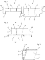
- the casing 1 with internal frame 2 mobile comprises a casing 3 intended to receive said internal frame 2.
- the inner frame 2 is, in operation, housed in the casing 3 of the casing 1, as shown in the leftmost view of the figure 1 and is, especially for maintenance, completely out of the envelope 3, as shown on the figure 2 .
- the most right view of the figure 1 represents the internal frame 2 during movement.
- the envelope 3 is preferably formed by different elements 4 defining generally the four sides 5 of a quadrilateral on which is advantageously mounted a bottom (not shown).
- This envelope 3 is intended to be preferably integrated in a false wall false ceiling type.
- Said elements 4 and the bottom forming the envelope 3 are advantageously, as in this example, made of structural elements, metal or not, the ceiling of the room receiving the false ceiling.
- these elements 4 and the bottom may, for example, be independent profiles bent sheet without departing from the scope of the present invention.
- the inner frame 2 is formed by a rail 6 itself consisting of abutting profiles on which is fixed at least a first flexible sheet 7 stretched.
- Smooth is an organ well known to those skilled in the art in the field of stretched false ceilings which is commonly used to maintain the flexible sheet of a suspended false ceiling.
- the inner frame 2 may be equipped with a second flexible ply 8 stretched above the first flexible ply 7.
- the first flexible ply 7 is translucent and the second flexible ply 8 is transparent. The latter has in particular the role of protecting the first flexible sheet 7 against dust and insects that could be deposited on it and which would then be visible by the users located in the room under said first flexible ply 7.
- the box 1 further comprises, to stiffen the inner frame 2, stiffening means (not shown) formed of at least one spar extending between two opposite profiles of the rail 6 of said inner frame 2 .
- the box 1 further comprises lighting means (not shown), such as neon tubes, advantageously mounted on the bottom of the envelope 3 said box 1.
- lighting means such as neon tubes
- said lighting means may be fixed on the "true ceiling" of the room receiving the false ceiling, without departing from the scope of the present invention.
- the inner frame 2 is movable by a movement successively combining a substantially vertical translation phase and a substantially horizontal translation phase.
- said box 1 comprises a mechanism 10 comprising at least one telescopic support 11 connecting two opposite sides of the inner frame 2 to the casing 3.
- the connection of the telescopic support 11 to the casing 3 can be performed using a support member 9 disposed within the casing 3.
- these two telescopic supports 11 are placed in the vertical plane containing the center of gravity of the internal framework 2.
- the mechanism 10 comprises two telescopic supports 11 connecting two opposite sides of the inner frame 2 to the envelope 3 and being arranged symmetrically on either side of the vertical plane containing the center of severity of the internal framework 2.
- Each telescopic support 11 is able to extend along a substantially vertical axis, it is fixed at its upper end to the casing 3 of the casing 1 and is secured at its lower end of the inner frame 2 by a "slide" connection.
- the inner frame 2 comprises on its upper face a longitudinal groove 21 in the general shape of inverted T, and the lower end of each telescopic support 11 comprises a slider 12 adapted to cooperate with said groove 21 to allow sliding in a substantially horizontal plane of the inner frame 2 relative to the telescopic support 11.
- the skilled person can easily replace the groove 21 and the slider 12 for any other suitable means such as, for example, an I-shaped rail and a rolling member without departing the frame of the present invention.
- the two telescopic supports 11 of each of the two opposite sides of the inner frame 2 are preferably spaced apart by a distance less than a quarter of the length of said opposite side.
- the casing 1 is advantageously provided with guide members (not shown) disposed on the periphery of the inner frame 2 to facilitate the repositioning of the internal frame inside the casing 3 of the box 1 during the vertical translation, said guide members preferably being rollers or balls.
- the casing 1 preferably comprises at least one closure (not shown) of the bolt type for example.
- the mechanism 10 may comprise only one central telescopic support 11 connecting the center of the bottom of the casing 3 to the two opposite sides of the inner frame 2, the telescopic support 11 then comprising an additional horizontal support connecting said two opposite sides of the inner frame 2.
- this variant is not satisfactory for reasons of stability but especially because the telescopic support 11 disposed in the box 1 in a central position hinders access to the the interior of the casing 1 and therefore makes maintenance difficult.
- the inner frame 2 is vertically translated through the telescopic supports 11 (Cf. figure 1 ); then, when the inner frame 2 is completely clear of the casing 3, the telescopic supports 11 being at the end of the stroke, it is then possible to translate the inner frame 2 in a horizontal plane on one side or the other of the envelope 3 in order to clear successively the entire lower surface of the casing 1, facilitating access to all the equipment contained in said box 1.
- the inner frame 2 is shown translated on one side (in bold line) and on the other (partially dotted) of the envelope 3.
- the casing 1 with internal frame 2 mobile according to the invention is preferably intended to be integrated alone to a false wall false ceiling type.
- said box 1 can obviously be arranged next to boxes of the same type, so as to form a lighting matrix.
- the box 1 according to the invention is light and simple construction, and that the inner frame 2 can be easily moved regardless of its dimensions.
Landscapes
- Engineering & Computer Science (AREA)
- Architecture (AREA)
- Physics & Mathematics (AREA)
- Electromagnetism (AREA)
- Civil Engineering (AREA)
- Structural Engineering (AREA)
- Tents Or Canopies (AREA)
- Casings For Electric Apparatus (AREA)
- Non-Portable Lighting Devices Or Systems Thereof (AREA)
Claims (8)
- Kasten (1), der zum Einbau in einer Vorwandung, wie zum Beispiel einer Zwischenwand, bestimmt ist und einen beweglichen Innenrahmen (2) enthält, an dessen Basis mindestens eine gespannte Bahn (7, 8) befestigt ist, ein Gehäuse (3) zur Aufnahme besagten Innenrahmens (2) und mindestens einen Mechanismus (10), der besagten Innenrahmen (2) mit besagtem Gehäuse (3) verbindet, wobei der besagte Kasten (1) dadurch gekennzeichnet ist, dass der Mechanismus (10) mindestens eine ausziehbare Halterung (11) umfasst, die sich an einer im Wesentlichen senkrechten Achse entlang erstrecken kann und an ihrem oberen Ende am Gehäuse (3) des Kastens (1) befestigt und an ihrem unteren Ende über eine "Schienenverbindung" fest mit dem Innenrahmen (2) verbunden ist, sodass der Innenrahmen (2) von einer Arbeitsstellung, in welcher er im Gehäuse (3) aufliegt, in eine Wartungsstellung wechselt, in welcher er durch eine Bewegung des besagten Innenrahmens (2) in Bezug auf besagtes Gehäuse (3) komplett aus dem Gehäuse (3) herausgeschoben wird, wobei eine im Wesentlichen senkrechte Translationsphase auf eine im wesentlichen waagrechte Translationsphase folgt.
- Kasten (1) nach Anspruch 1, dadurch gekennzeichnet, dass der Mechanismus (10) mindestens eine ausziehbare Halterung (11) umfasst, die zwei gegenüberliegende Seiten des Innenrahmens (2) mit dem Gehäuse (3) verbindet, wobei die ausziehbaren Halterungen (11) in der senkrechten Ebene, welche den Schwerpunkt des Innenrahmens (2) enthält, platziert werden.
- Kasten (1) nach Anspruch 2, dadurch gekennzeichnet, dass der Mechanismus (10) zwei ausziehbare Halterungen (11) umfasst, welche zwei gegenüberliegende Seiten des Innenrahmens (2) mit dem Gehäuse (3) verbinden, wobei besagte ausziehbare Halterungen (11) zu beiden Seiten der senkrechten Ebene, welche den Schwerpunkt des Innenrahmens (2) enthält, symmetrisch angeordnet sind.
- Kasten (1) nach Anspruch 3, dadurch gekennzeichnet, dass die beiden ausziehbaren Halterungen (11) zu jeder der beiden gegenüberliegenden Seiten des Innenrahmens (2) in einer Entfernung zueinander beanstandet sind, die weniger als ein Viertel der Länge der besagten gegenüberliegenden Seite beträgt.
- Kasten (1) nach einem der Ansprüche 1 bis 4, dadurch gekennzeichnet, dass der Innenrahmen (2) an seiner Oberseite eine Längsrille (21) im Allgemeinen in Form eines umgedrehten T enthält, und dadurch, dass das untere Ende jeder ausziehbaren Halterung (11) ein Gleitstück (12) enthält, das in der Lage ist, mit besagter Rille (21) zusammen zu wirken, um das Verschieben des inneren Rahmens (2) in Bezug auf die ausziehbare Halterung (11) in der Waagrechten zu ermöglichen.
- Kasten (1) nach einem der vorhergehenden Ansprüche, dadurch gekennzeichnet, dass der Kasten (1) mit Führungselementen versehen ist, die am Umfang des Innenrahmens (2) befestigt sind.
- Kasten (1) nach einem der vorhergehenden Ansprüche, dadurch gekennzeichnet, dass der Kasten (1) an der Außenkontur des Innenrahmens (2) mit einer Dichtung versehen ist.
- Kasten (1) nach einem der vorhergehenden Ansprüche, dadurch gekennzeichnet, dass der Kasten (1) mindestens einen Schieberiegel als Verschluss enthält.
Applications Claiming Priority (1)
| Application Number | Priority Date | Filing Date | Title |
|---|---|---|---|
| FR1102531A FR2979116B1 (fr) | 2011-08-17 | 2011-08-17 | Caisson lumineux a cadre mobile. |
Publications (2)
| Publication Number | Publication Date |
|---|---|
| EP2559822A1 EP2559822A1 (de) | 2013-02-20 |
| EP2559822B1 true EP2559822B1 (de) | 2018-12-12 |
Family
ID=46642449
Family Applications (1)
| Application Number | Title | Priority Date | Filing Date |
|---|---|---|---|
| EP12180700.2A Active EP2559822B1 (de) | 2011-08-17 | 2012-08-16 | Leuchtkasten mit beweglichem inneren Rahmen |
Country Status (2)
| Country | Link |
|---|---|
| EP (1) | EP2559822B1 (de) |
| FR (1) | FR2979116B1 (de) |
Cited By (2)
| Publication number | Priority date | Publication date | Assignee | Title |
|---|---|---|---|---|
| RU203036U1 (ru) * | 2020-11-30 | 2021-03-18 | Алексей Алексеевич Сатаров | Профиль для монтажа натяжного потолка |
| RU2809371C1 (ru) * | 2023-10-03 | 2023-12-11 | Алексей Михайлович Леготкин | Узел крепления для монтажа многоуровневого натяжного потолка |
Families Citing this family (2)
| Publication number | Priority date | Publication date | Assignee | Title |
|---|---|---|---|---|
| FR3010424B1 (fr) * | 2013-09-10 | 2015-09-25 | Normalu | <p>systeme de fixation pour la realisation de revetements tendus</p> |
| FR3140638A1 (fr) * | 2022-10-05 | 2024-04-12 | Newmat | Elément profilé pour dalle à toile tendue et dalle comprenant un tel élément profilé |
Family Cites Families (3)
| Publication number | Priority date | Publication date | Assignee | Title |
|---|---|---|---|---|
| DE2927166A1 (de) * | 1979-07-05 | 1981-01-08 | Hermann J Kleine | Deckenverkleidung mit mindestens einer deckenplatte oder -tafel bzw. einem deckenpaneel |
| EP2048299B1 (de) * | 2004-01-28 | 2017-04-19 | Soft Cells A/S | Abdeckelement insbesondere für abgehängte Decken |
| FR2911619B1 (fr) * | 2007-01-24 | 2010-12-31 | Normalu | Dispositif a caisson mobile. |
-
2011
- 2011-08-17 FR FR1102531A patent/FR2979116B1/fr active Active
-
2012
- 2012-08-16 EP EP12180700.2A patent/EP2559822B1/de active Active
Non-Patent Citations (1)
| Title |
|---|
| None * |
Cited By (2)
| Publication number | Priority date | Publication date | Assignee | Title |
|---|---|---|---|---|
| RU203036U1 (ru) * | 2020-11-30 | 2021-03-18 | Алексей Алексеевич Сатаров | Профиль для монтажа натяжного потолка |
| RU2809371C1 (ru) * | 2023-10-03 | 2023-12-11 | Алексей Михайлович Леготкин | Узел крепления для монтажа многоуровневого натяжного потолка |
Also Published As
| Publication number | Publication date |
|---|---|
| FR2979116B1 (fr) | 2016-12-09 |
| FR2979116A1 (fr) | 2013-02-22 |
| EP2559822A1 (de) | 2013-02-20 |
Similar Documents
| Publication | Publication Date | Title |
|---|---|---|
| FR2975420A1 (fr) | Dispositif d'obturation au moins partielle d'une cavite ouverte par le dessus | |
| EP2559822B1 (de) | Leuchtkasten mit beweglichem inneren Rahmen | |
| CA2783706A1 (fr) | Mecanisme d'articulation frangible pour une cloison de plateforme, cloison, ensemble et procede associes | |
| CA2598500C (fr) | Caisson a raidisseur invisible | |
| EP2401443B1 (de) | Leuchtkasten mit drehtranslationsöffnung | |
| EP2401442B1 (de) | Leuchtkasten mit öffnung durch einen federbelasteten feststeller | |
| FR2970019A1 (fr) | Caisson lumineux a charniere a bras telescopique | |
| EP2494121B3 (de) | Zwischenwandvorrichtung | |
| EP1400653A1 (de) | Schiebefenster oder -tür, dessen Flügel gegen einer an der Zarge angeordneten Abdichtung verriegelbar sind | |
| EP2904176B1 (de) | Beckenabdeckung | |
| FR2804984A1 (fr) | Systeme d'echafaudage pour capacites de formes diverses | |
| EP2313593B1 (de) | Tür für das schutzdach eines schwimmbads | |
| FR2927117A1 (fr) | Dispositif permettant l'ouverture d'un portail ou tout autre ouvrant dans une pente montante | |
| FR2581303A1 (fr) | Structure de vitrine | |
| FR2974132A1 (fr) | Dispositif pour le basculement d'au moins un caisson mobile monte sur une paroi telle qu'un mur ou un plafond. | |
| EP3400622A1 (de) | Stationärer schutzraum zur aufbewahrung von mindestens einer stromspeichereinheit | |
| FR3102452A1 (fr) | Caisson comprenant une porte de type accordeon a multiples panneaux pour un vehicule automobile | |
| EP3400190B1 (de) | Stationärer schutzraum zur aufbewahrung von mindestens einer stromspeichereinheit | |
| FR3020649A1 (fr) | Abri de piscine a modules telescopiques comprenant un mecanisme de deplacement ameliore des modules | |
| EP3830643A1 (de) | Vorrichtung zur aufnahme eines packshots | |
| FR2957375A1 (fr) | Abri de piscine compose de plusieurs modules | |
| FR3074509A1 (fr) | Element de couverture, abri et procede associe | |
| EP2505054B1 (de) | Hochfahrende, schwenkbare Trennwand | |
| FR3145857A3 (fr) | Utilisation d’une paroi dans une douche ou baignoire, et douche ou baignoire munie d’une telle paroi | |
| FR2614341A1 (fr) | Perfectionnements aux plates-formes constituant structure de plancher mobile |
Legal Events
| Date | Code | Title | Description |
|---|---|---|---|
| PUAI | Public reference made under article 153(3) epc to a published international application that has entered the european phase |
Free format text: ORIGINAL CODE: 0009012 |
|
| AK | Designated contracting states |
Kind code of ref document: A1 Designated state(s): AL AT BE BG CH CY CZ DE DK EE ES FI FR GB GR HR HU IE IS IT LI LT LU LV MC MK MT NL NO PL PT RO RS SE SI SK SM TR |
|
| AX | Request for extension of the european patent |
Extension state: BA ME |
|
| 17P | Request for examination filed |
Effective date: 20130820 |
|
| STAA | Information on the status of an ep patent application or granted ep patent |
Free format text: STATUS: EXAMINATION IS IN PROGRESS |
|
| RIC1 | Information provided on ipc code assigned before grant |
Ipc: E04B 9/24 20060101ALI20161109BHEP Ipc: E04B 9/00 20060101AFI20161109BHEP Ipc: E04B 9/20 20060101ALI20161109BHEP Ipc: E04B 9/04 20060101ALI20161109BHEP |
|
| 17Q | First examination report despatched |
Effective date: 20161201 |
|
| GRAP | Despatch of communication of intention to grant a patent |
Free format text: ORIGINAL CODE: EPIDOSNIGR1 |
|
| STAA | Information on the status of an ep patent application or granted ep patent |
Free format text: STATUS: GRANT OF PATENT IS INTENDED |
|
| INTG | Intention to grant announced |
Effective date: 20180712 |
|
| GRAJ | Information related to disapproval of communication of intention to grant by the applicant or resumption of examination proceedings by the epo deleted |
Free format text: ORIGINAL CODE: EPIDOSDIGR1 |
|
| STAA | Information on the status of an ep patent application or granted ep patent |
Free format text: STATUS: EXAMINATION IS IN PROGRESS |
|
| GRAS | Grant fee paid |
Free format text: ORIGINAL CODE: EPIDOSNIGR3 |
|
| STAA | Information on the status of an ep patent application or granted ep patent |
Free format text: STATUS: GRANT OF PATENT IS INTENDED |
|
| GRAP | Despatch of communication of intention to grant a patent |
Free format text: ORIGINAL CODE: EPIDOSNIGR1 |
|
| GRAA | (expected) grant |
Free format text: ORIGINAL CODE: 0009210 |
|
| STAA | Information on the status of an ep patent application or granted ep patent |
Free format text: STATUS: THE PATENT HAS BEEN GRANTED |
|
| INTC | Intention to grant announced (deleted) | ||
| INTG | Intention to grant announced |
Effective date: 20181029 |
|
| AK | Designated contracting states |
Kind code of ref document: B1 Designated state(s): AL AT BE BG CH CY CZ DE DK EE ES FI FR GB GR HR HU IE IS IT LI LT LU LV MC MK MT NL NO PL PT RO RS SE SI SK SM TR |
|
| REG | Reference to a national code |
Ref country code: GB Ref legal event code: FG4D Free format text: NOT ENGLISH |
|
| REG | Reference to a national code |
Ref country code: CH Ref legal event code: EP |
|
| REG | Reference to a national code |
Ref country code: AT Ref legal event code: REF Ref document number: 1076157 Country of ref document: AT Kind code of ref document: T Effective date: 20181215 |
|
| REG | Reference to a national code |
Ref country code: DE Ref legal event code: R096 Ref document number: 602012054567 Country of ref document: DE |
|
| REG | Reference to a national code |
Ref country code: IE Ref legal event code: FG4D Free format text: LANGUAGE OF EP DOCUMENT: FRENCH |
|
| REG | Reference to a national code |
Ref country code: NL Ref legal event code: MP Effective date: 20181212 |
|
| REG | Reference to a national code |
Ref country code: LT Ref legal event code: MG4D |
|
| PG25 | Lapsed in a contracting state [announced via postgrant information from national office to epo] |
Ref country code: HR Free format text: LAPSE BECAUSE OF FAILURE TO SUBMIT A TRANSLATION OF THE DESCRIPTION OR TO PAY THE FEE WITHIN THE PRESCRIBED TIME-LIMIT Effective date: 20181212 Ref country code: LT Free format text: LAPSE BECAUSE OF FAILURE TO SUBMIT A TRANSLATION OF THE DESCRIPTION OR TO PAY THE FEE WITHIN THE PRESCRIBED TIME-LIMIT Effective date: 20181212 Ref country code: NO Free format text: LAPSE BECAUSE OF FAILURE TO SUBMIT A TRANSLATION OF THE DESCRIPTION OR TO PAY THE FEE WITHIN THE PRESCRIBED TIME-LIMIT Effective date: 20190312 Ref country code: ES Free format text: LAPSE BECAUSE OF FAILURE TO SUBMIT A TRANSLATION OF THE DESCRIPTION OR TO PAY THE FEE WITHIN THE PRESCRIBED TIME-LIMIT Effective date: 20181212 Ref country code: LV Free format text: LAPSE BECAUSE OF FAILURE TO SUBMIT A TRANSLATION OF THE DESCRIPTION OR TO PAY THE FEE WITHIN THE PRESCRIBED TIME-LIMIT Effective date: 20181212 Ref country code: BG Free format text: LAPSE BECAUSE OF FAILURE TO SUBMIT A TRANSLATION OF THE DESCRIPTION OR TO PAY THE FEE WITHIN THE PRESCRIBED TIME-LIMIT Effective date: 20190312 Ref country code: FI Free format text: LAPSE BECAUSE OF FAILURE TO SUBMIT A TRANSLATION OF THE DESCRIPTION OR TO PAY THE FEE WITHIN THE PRESCRIBED TIME-LIMIT Effective date: 20181212 |
|
| REG | Reference to a national code |
Ref country code: AT Ref legal event code: MK05 Ref document number: 1076157 Country of ref document: AT Kind code of ref document: T Effective date: 20181212 |
|
| PG25 | Lapsed in a contracting state [announced via postgrant information from national office to epo] |
Ref country code: GR Free format text: LAPSE BECAUSE OF FAILURE TO SUBMIT A TRANSLATION OF THE DESCRIPTION OR TO PAY THE FEE WITHIN THE PRESCRIBED TIME-LIMIT Effective date: 20190313 Ref country code: RS Free format text: LAPSE BECAUSE OF FAILURE TO SUBMIT A TRANSLATION OF THE DESCRIPTION OR TO PAY THE FEE WITHIN THE PRESCRIBED TIME-LIMIT Effective date: 20181212 Ref country code: SE Free format text: LAPSE BECAUSE OF FAILURE TO SUBMIT A TRANSLATION OF THE DESCRIPTION OR TO PAY THE FEE WITHIN THE PRESCRIBED TIME-LIMIT Effective date: 20181212 Ref country code: AL Free format text: LAPSE BECAUSE OF FAILURE TO SUBMIT A TRANSLATION OF THE DESCRIPTION OR TO PAY THE FEE WITHIN THE PRESCRIBED TIME-LIMIT Effective date: 20181212 |
|
| PG25 | Lapsed in a contracting state [announced via postgrant information from national office to epo] |
Ref country code: NL Free format text: LAPSE BECAUSE OF FAILURE TO SUBMIT A TRANSLATION OF THE DESCRIPTION OR TO PAY THE FEE WITHIN THE PRESCRIBED TIME-LIMIT Effective date: 20181212 |
|
| PG25 | Lapsed in a contracting state [announced via postgrant information from national office to epo] |
Ref country code: IT Free format text: LAPSE BECAUSE OF FAILURE TO SUBMIT A TRANSLATION OF THE DESCRIPTION OR TO PAY THE FEE WITHIN THE PRESCRIBED TIME-LIMIT Effective date: 20181212 Ref country code: PT Free format text: LAPSE BECAUSE OF FAILURE TO SUBMIT A TRANSLATION OF THE DESCRIPTION OR TO PAY THE FEE WITHIN THE PRESCRIBED TIME-LIMIT Effective date: 20190412 Ref country code: CZ Free format text: LAPSE BECAUSE OF FAILURE TO SUBMIT A TRANSLATION OF THE DESCRIPTION OR TO PAY THE FEE WITHIN THE PRESCRIBED TIME-LIMIT Effective date: 20181212 Ref country code: PL Free format text: LAPSE BECAUSE OF FAILURE TO SUBMIT A TRANSLATION OF THE DESCRIPTION OR TO PAY THE FEE WITHIN THE PRESCRIBED TIME-LIMIT Effective date: 20181212 |
|
| PG25 | Lapsed in a contracting state [announced via postgrant information from national office to epo] |
Ref country code: SK Free format text: LAPSE BECAUSE OF FAILURE TO SUBMIT A TRANSLATION OF THE DESCRIPTION OR TO PAY THE FEE WITHIN THE PRESCRIBED TIME-LIMIT Effective date: 20181212 Ref country code: SM Free format text: LAPSE BECAUSE OF FAILURE TO SUBMIT A TRANSLATION OF THE DESCRIPTION OR TO PAY THE FEE WITHIN THE PRESCRIBED TIME-LIMIT Effective date: 20181212 Ref country code: IS Free format text: LAPSE BECAUSE OF FAILURE TO SUBMIT A TRANSLATION OF THE DESCRIPTION OR TO PAY THE FEE WITHIN THE PRESCRIBED TIME-LIMIT Effective date: 20190412 Ref country code: RO Free format text: LAPSE BECAUSE OF FAILURE TO SUBMIT A TRANSLATION OF THE DESCRIPTION OR TO PAY THE FEE WITHIN THE PRESCRIBED TIME-LIMIT Effective date: 20181212 Ref country code: EE Free format text: LAPSE BECAUSE OF FAILURE TO SUBMIT A TRANSLATION OF THE DESCRIPTION OR TO PAY THE FEE WITHIN THE PRESCRIBED TIME-LIMIT Effective date: 20181212 |
|
| REG | Reference to a national code |
Ref country code: DE Ref legal event code: R097 Ref document number: 602012054567 Country of ref document: DE |
|
| PLBE | No opposition filed within time limit |
Free format text: ORIGINAL CODE: 0009261 |
|
| STAA | Information on the status of an ep patent application or granted ep patent |
Free format text: STATUS: NO OPPOSITION FILED WITHIN TIME LIMIT |
|
| PG25 | Lapsed in a contracting state [announced via postgrant information from national office to epo] |
Ref country code: AT Free format text: LAPSE BECAUSE OF FAILURE TO SUBMIT A TRANSLATION OF THE DESCRIPTION OR TO PAY THE FEE WITHIN THE PRESCRIBED TIME-LIMIT Effective date: 20181212 Ref country code: SI Free format text: LAPSE BECAUSE OF FAILURE TO SUBMIT A TRANSLATION OF THE DESCRIPTION OR TO PAY THE FEE WITHIN THE PRESCRIBED TIME-LIMIT Effective date: 20181212 Ref country code: DK Free format text: LAPSE BECAUSE OF FAILURE TO SUBMIT A TRANSLATION OF THE DESCRIPTION OR TO PAY THE FEE WITHIN THE PRESCRIBED TIME-LIMIT Effective date: 20181212 |
|
| 26N | No opposition filed |
Effective date: 20190913 |
|
| REG | Reference to a national code |
Ref country code: DE Ref legal event code: R119 Ref document number: 602012054567 Country of ref document: DE |
|
| PG25 | Lapsed in a contracting state [announced via postgrant information from national office to epo] |
Ref country code: TR Free format text: LAPSE BECAUSE OF FAILURE TO SUBMIT A TRANSLATION OF THE DESCRIPTION OR TO PAY THE FEE WITHIN THE PRESCRIBED TIME-LIMIT Effective date: 20181212 |
|
| GBPC | Gb: european patent ceased through non-payment of renewal fee |
Effective date: 20190816 |
|
| PG25 | Lapsed in a contracting state [announced via postgrant information from national office to epo] |
Ref country code: CH Free format text: LAPSE BECAUSE OF NON-PAYMENT OF DUE FEES Effective date: 20190831 Ref country code: MC Free format text: LAPSE BECAUSE OF FAILURE TO SUBMIT A TRANSLATION OF THE DESCRIPTION OR TO PAY THE FEE WITHIN THE PRESCRIBED TIME-LIMIT Effective date: 20181212 Ref country code: LI Free format text: LAPSE BECAUSE OF NON-PAYMENT OF DUE FEES Effective date: 20190831 Ref country code: LU Free format text: LAPSE BECAUSE OF NON-PAYMENT OF DUE FEES Effective date: 20190816 |
|
| REG | Reference to a national code |
Ref country code: BE Ref legal event code: MM Effective date: 20190831 |
|
| PG25 | Lapsed in a contracting state [announced via postgrant information from national office to epo] |
Ref country code: IE Free format text: LAPSE BECAUSE OF NON-PAYMENT OF DUE FEES Effective date: 20190816 Ref country code: DE Free format text: LAPSE BECAUSE OF NON-PAYMENT OF DUE FEES Effective date: 20200303 |
|
| PG25 | Lapsed in a contracting state [announced via postgrant information from national office to epo] |
Ref country code: BE Free format text: LAPSE BECAUSE OF NON-PAYMENT OF DUE FEES Effective date: 20190831 Ref country code: GB Free format text: LAPSE BECAUSE OF NON-PAYMENT OF DUE FEES Effective date: 20190816 |
|
| PG25 | Lapsed in a contracting state [announced via postgrant information from national office to epo] |
Ref country code: CY Free format text: LAPSE BECAUSE OF FAILURE TO SUBMIT A TRANSLATION OF THE DESCRIPTION OR TO PAY THE FEE WITHIN THE PRESCRIBED TIME-LIMIT Effective date: 20181212 |
|
| PG25 | Lapsed in a contracting state [announced via postgrant information from national office to epo] |
Ref country code: MT Free format text: LAPSE BECAUSE OF FAILURE TO SUBMIT A TRANSLATION OF THE DESCRIPTION OR TO PAY THE FEE WITHIN THE PRESCRIBED TIME-LIMIT Effective date: 20181212 Ref country code: HU Free format text: LAPSE BECAUSE OF FAILURE TO SUBMIT A TRANSLATION OF THE DESCRIPTION OR TO PAY THE FEE WITHIN THE PRESCRIBED TIME-LIMIT; INVALID AB INITIO Effective date: 20120816 |
|
| PG25 | Lapsed in a contracting state [announced via postgrant information from national office to epo] |
Ref country code: MK Free format text: LAPSE BECAUSE OF FAILURE TO SUBMIT A TRANSLATION OF THE DESCRIPTION OR TO PAY THE FEE WITHIN THE PRESCRIBED TIME-LIMIT Effective date: 20181212 |
|
| PGFP | Annual fee paid to national office [announced via postgrant information from national office to epo] |
Ref country code: FR Payment date: 20250923 Year of fee payment: 14 |