EP2559836A2 - Coffret à argent avec cartouche d'encre échangeable séparément - Google Patents
Coffret à argent avec cartouche d'encre échangeable séparément Download PDFInfo
- Publication number
- EP2559836A2 EP2559836A2 EP20120180237 EP12180237A EP2559836A2 EP 2559836 A2 EP2559836 A2 EP 2559836A2 EP 20120180237 EP20120180237 EP 20120180237 EP 12180237 A EP12180237 A EP 12180237A EP 2559836 A2 EP2559836 A2 EP 2559836A2
- Authority
- EP
- European Patent Office
- Prior art keywords
- dye
- unit
- dye tank
- tube
- cashbox
- Prior art date
- Legal status (The legal status is an assumption and is not a legal conclusion. Google has not performed a legal analysis and makes no representation as to the accuracy of the status listed.)
- Granted
Links
Images


Classifications
-
- E—FIXED CONSTRUCTIONS
- E05—LOCKS; KEYS; WINDOW OR DOOR FITTINGS; SAFES
- E05G—SAFES OR STRONG-ROOMS FOR VALUABLES; BANK PROTECTION DEVICES; SAFETY TRANSACTION PARTITIONS
- E05G1/00—Safes or strong-rooms for valuables
- E05G1/005—Portable strong boxes, e.g. which may be fixed to a wall or the like
-
- E—FIXED CONSTRUCTIONS
- E05—LOCKS; KEYS; WINDOW OR DOOR FITTINGS; SAFES
- E05G—SAFES OR STRONG-ROOMS FOR VALUABLES; BANK PROTECTION DEVICES; SAFETY TRANSACTION PARTITIONS
- E05G1/00—Safes or strong-rooms for valuables
- E05G1/14—Safes or strong-rooms for valuables with means for masking or destroying the valuables, e.g. in case of theft
Definitions
- the invention relates to a cash box comprising a housing and an insertable into the housing and removable from the housing storage unit for storing bank notes. Further, the cash box has a devaluation unit for irreversibly debiting the notes stored in the storage unit, which comprises a dye tank and at least one spray unit for spraying the dye received in the dye tank onto the notes of value.
- the cashbox may be a cashbox in which the banknotes are stored in a reel store. In such a reel storage the notes of value between two wound films are stored one behind the other. Alternatively, it may also be a cash box, in which the notes of value are received in a receptacle in a stacked form.
- cash boxes are equipped with so-called ink kits, with the help of which recorded in the cashbox banknotes irreversible in the presence of a manipulation attempt Be stained with a dye so that they are from the manipulation exporting person can no longer be put into circulation and thus are useless for this.
- the ink kits comprise in particular a dye container in which the dye is incorporated, a pressurized gas pressure cartridge which is separated by a rupture disk in front of the dye contained in the dye container, a spray unit for spraying the dye on the bank notes, a bolt for breaking the rupture disk, a detonator and an igniter to detonate the detonator.
- the detonator Upon detection of a tampering attempt, the detonator detonates the detonator, which then fires the bolt towards the bursting disk so that it may break and thus flow the high pressure gas from the gas pressure cartridge and transfer the dye to the spray nozzle at high speed Vouchers sprayed.
- a unit formed from the aforementioned components is attached to the lid of the cashbox.
- the ink kit must be replaced at regular intervals as it will only function for a predetermined time.
- the entire ink kit is replaced by being unscrewed from the lid of the cash box and replaced by a new one.
- This replacement of the ink kit is time consuming and costly because on the one hand all components of the ink kit are exchanged, including those that are not subject to aging, and on the other by the screwing and unscrewing the ink kit much time is needed.
- An ink kit is for example from the non-prepublished application DE 10 2010 016 970 known.
- the also not previously published application DE 10 2010 016 808 discloses a roller storage with two spray units for spraying the dye.
- the storage unit comprises the spray unit. Furthermore, the storage unit has at least one receiving element which, together with the housing, at least partially delimits a receiving area for receiving the dye tank.
- the fixed arrangement of the spray unit to the storage unit ensures that it is no longer necessary to replace the entire validation unit, but instead only to exchange the dye tank.
- This exchangeable dye container in the receiving area and the housing limited receiving area is achieved that the dye tank can be easily replaced quickly and this does not require consuming other components of the cashbox must be removed and not consuming to manufacture parts for mounting the Dye tanks are necessary.
- the storage unit comprises in particular a roller storage in which the banknotes to be stored are stored between two films stored together with the films wound on a winding drum.
- the storage unit may also include a storage compartment for receiving the stored banknote, in which the banknotes in stacked form, in particular standing on their edges, are added.
- the storage unit comprises a plurality of transport elements for feeding the notes of value to the roll storage or to the storage compartment and / or for removing the notes of value from the roll storage or from the storage compartment.
- the storage unit may have at least one drive unit for driving the transport elements and / or the roller storage and a control unit for controlling the units of the cashbox.
- the storage unit is understood in particular to mean the unit which is formed from all components of the cash box, with the exception of the housing and the exchangeable dye tank, and which can be inserted as a whole into the housing and removed from the housing.
- the housing in particular comprises a base body with an opening for insertion and removal of the storage unit and a lid for closing this opening.
- the lid can be removable or hinged.
- the dye tank is in particular designed such that at least a portion of it is cylindrical.
- the receiving element has in particular at least one circular segment-shaped Contact area, by which the receiving area for receiving the dye tank is at least partially limited and the cylindrical portion of the dye tank when it is received in the receiving area, contacted.
- the contact region is formed in particular complementary to the cylindrical portion of the dye container. In a particularly preferred embodiment, the contact region is semi-circular in shape.
- the receiving element is a first receiving element and if a further, second receiving element is provided, by which the receiving area for receiving the dye container is also at least partially limited.
- the second receiving element and the first receiving element are in particular identical.
- the dye tank is held in particular by the housing and by the receiving element in the receiving area, preferably clamped.
- At least one the dye tank at least partially, preferably completely, enclosing fastener is provided, via which the dye tank is attached to the storage unit.
- a cable tie is used in particular, which is passed through an adjacent to the receiving area arranged tab of the storage unit and completely encloses the dye tank.
- the cable tie can be both a cable tie which can only be removed by destroying the cable tie and a reusable cable tie, i. H. a cable tie that can be both loosened and re-attached act.
- the latter has the advantage that the cable tie can be reused when replacing the dye tank.
- two connectable via a Velcro connection bands and / or two can be connected to each other via a snap-in connection bands.
- the dye tank comprises a dye container filled with the dye and a triggering unit for triggering the devaluation unit.
- the trip unit has a gas pressure cartridge, a detonator and an igniter.
- the detonator can be ignited, which in particular a bolt shot through a rupture disk of the gas pressure cartridge so that this rupture disc bursts and the gas taken up under a high pressure in the gas pressure cartridge flows into the dye container and sprays the dye from the nozzles of the spray unit onto the rail.
- the dye container including the dye contained in it, the gas pressure cartridge, the detonator and detonator can be exchanged as a unit, so that this a natural aging process, which jeopardizes the functioning of the devaluation unit subject components can be easily exchanged together.
- the dye tank is preferably connectable to the spray unit via a connection line for passing the dye from the dye tank to the spray unit, which connection line is attached to the storage unit and is preferably part of the storage unit.
- the connecting line can be connected via a detachable and recoverable connection with the dye container, so that it can be exchanged in a simple manner, without the spray unit and / or the connecting lines having to be exchanged.
- the connecting line comprises in particular a tube which is inserted for producing the detachable and recoverable connection in a complementary to the tube formed recess of a connection element of the ink tank.
- connection between the end region of the tube and the connecting element is sealed in particular by at least one sealing element, preferably at least one O-ring, so that dye is only transported from the dye tank into the connecting line when the devaluation unit is triggered, and undesired discharge of dye at the connecting point between the dye tank and the connection line is prevented.
- the O-ring can be held both at the end of the tube and in the recess.
- at least two O-rings are provided, so that a particularly reliable sealing is achieved.
- the tube is reliably held in the recess even when releasing the devaluation unit.
- a clamping connection via the O-rings is formed.
- a the end region opposite further end portion of the tube is inserted in particular in a recess of the spray unit, so that when triggering the devaluation unit, the tube is reliably held both in the recess of the connection element of the dye tank and in the recess of the spray, so that the dye reliably through the pipe can be passed.
- a further tube of which an end portion is inserted into the recess of the spray unit. This further tube and the previously described, inserted into the recess of the dye tank tube can be connected to each other directly or via other elements, such as a hose.
- the storage unit comprises a further spray unit, via which also the dye received in the dye tank can be sprayed onto the notes of value stored in the storage unit.
- the two spray units are arranged in particular on mutually opposite sides of the roller storage or the storage compartment, so that a reliable coloring of all stored notes of value is achieved.
- connection element of the dye tank comprises in particular a further recess into which an end region of a pipe of the further connection line is inserted, so that the further connection line and thus the further spray unit can be connected in a simple manner to the dye tank and even when using two spray units a simple Assembly of the dye tank is possible.
- only one dye tank is provided via which both spray units are supplied with the dye.
- the further connecting line can in particular be developed further with the features described above for the one connecting line.
- the dye tank comprises an igniter for triggering the devaluation unit and if the storage unit has a control unit, via which this igniter can be controlled.
- a signal for triggering the igniter and thus for triggering the devaluation unit can be transmitted to the igniter via the control unit.
- a first cable which is fixedly connected to the igniter
- a second cable which is fixedly connected to the control unit.
- a first connector and on the second cable complementary to the first connector formed second connector is provided, via which a releasable and recoverable plug connection between the two cables can be produced.
- FIG. 1 is a schematic, perspective view, in FIG. 2 an exploded view and in FIG. 3 a sectional view of a cashbox 10 is shown.
- the cash box 10 comprises a housing 12 having a base body 14 and a cover 16, a storage unit 20 which can be inserted into the housing 12 and removed from the housing 12, and a dye tank 22.
- FIG. 12 is a schematic perspective view of the storage unit 20 with a portion of the cover of the storage unit hidden to better reveal the internal components of the storage unit 20 that are protected by it.
- the storage unit 20 comprises a roller storage 24, with the aid of which the notes of value to be stored are stored wound up on a winding drum 26 between two films.
- the winding drum 26 can be driven via a drive unit 28, so that the notes of value are wound onto the roll storage 24 or unwound from the roll storage 24, depending on the direction of rotation of the winding drum 26.
- the storage unit 20 comprises a plurality of
- a slot 18 is formed between the lid 16 and the base body 14, through which the money cassette 10 to be supplied and / or the cashbox 10 to be taken notes of value are transported through ,
- the storage unit 24 has a first spray unit 32 and a second spray unit 34 opposite the first storage unit 32 relative to the roller storage 24, each having a spray plate 36 in which a plurality of nozzles 38 are arranged.
- a recorded in the dye tank 22 dye can be sprayed onto the wound on the reel store 24 notes of value, so that these notes of value are irreversibly dyed with the dye and thus devalued irreversible.
- the notes devalued in this way are useless for a potential thief, as this can not bring the notes unnoticed in circulation.
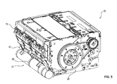
- FIG. 5 is a schematic, perspective view of the storage unit 20 and the attached to the storage unit 20 via a detachable and recoverable connection attached dye tanks 22.
- This assembly formed from the storage unit 20 and the dye tank 22 is used in the assembly as a whole through the opening of the base body 14, which is otherwise closed by the lid 16, in the base body 14, so that a particularly simple installation is possible.
- the storage unit 20 comprises a receiving element 40, by means of which, together with the housing 12, in particular the main body 14 of the housing 12, a receiving area 42 is delimited, in which the dye tank 22 is accommodated.
- the spray units 32, 34 are fixedly connected to the other components of the storage unit 20, in particular arranged between other components of the storage unit 20, so that a particularly compact space-saving, construction of the storage unit 20 is achieved.
- FIGS. 6 to 8 in each case a schematic perspective view of a section of the storage unit 20 of the dye tank 22 is shown.
- the cutout of the storage unit 20 is selected such that only the receiving element 40, the spray units 32, 34 and corresponding means for attaching the dye tank 22 to the storage unit 20 and for supplying the dye received in the dye tank 22 to the spray units 32, 34 are shown.
- FIG. 9 shows a schematic perspective view of the section of the storage unit 20 after the FIGS. 6 to 8 .
- the dye tank 22 must be replaced regularly, since its components undergo an aging process, through which the function of the devaluation unit formed by the dye tank 22 and the spray units 32, 34 irreversible Canceled value of the notes is no longer guaranteed.
- the dye tank 22 comprises a dye container 50 in which the dye is incorporated. Furthermore, the dye tank 22 has an igniter 52, by means of which a detonator 54 can be ignited. When igniting the detonator 54, a bolt 56 is pushed through a rupture disc of a gas pressure cartridge 58, so that bursts this rupture disk and the gas taken in the gas pressure cartridge 58 under high pressure gas flows into the dye container. As a result, the dye is conveyed through an opening 62 in a connecting element 60 and transported via two recesses 64, 66 in a first connecting line 70 for supplying dye to the first spray unit 32 and a second connecting line 72 for supplying dye to the second spray unit 34.
- the receiving member 40 has two semicircular contact areas 80, 82 and a circular segment-shaped contact area 84, which contact the cylindrical dye container 50 of the dye tank 22 when the dye tank 22 is attached to the storage unit 20, and thus hold the dye tank 22 in the receiving area 42.
- the dye tank 22 is attached to the storage unit 20 via a cable tie 86, which encloses the dye container 50 of the dye tank 22 in the region of the circular segment-shaped contact region 84 and is guided by a tab 88 formed in the region of the contact region 84.
- a cable tie 86 achieves a particularly simple attachment of the dye tank 22 to the storage unit 20.
- the can from the dye tank 22 and storage unit 20 unit formed in a simple manner in the housing 12 are used.
- the dye container 50 of the dye tank 22 has in the region of the cable tie 86 has a recess 90 through which the cable tie 86 is guided, so that slippage of the dye tank 22 is avoided in its longitudinal direction.
- the fastening can also take place via a band or a plurality of bands which can be connected to one another via a hook-and-loop connection and / or latching connection.
- the cable tie 86 can be both a closable and reopenable cable tie 86 and a cable tie 86 that is removable only by destruction.
- the first connection line 70 has a tube 92, the first end portion 94 is loosely inserted into the first recess 64 of the connection element 60 of the dye tank 22.
- the sealing takes place via two O-rings 96 arranged on the end region 94, by which on the one hand the sealing and on the other hand an attachment of the tube 92 in the connection element 60 is achieved, so that, even if the gas pressure cartridge 58 is triggered, that tube 92 remains in the recess 64.
- a first end region 94 opposite the second end region of the tube 92 is loosely inserted into a connection element 98 of the first spray unit 32, and, preferably also via at least one O-ring 96, sealed.
- a first connection line 70 for supplying dye from the dye tank 22 to the first spray unit 32 is easily formed.
- a simple, rapid assembly of the dye tank 22 can be achieved by the loose insertion of the tube 92 into the connection element 60.
- the second connection line 72 comprises a tube 100, wherein a first end portion 102 of the tube 100 is loosely inserted into the second recess 66 of the connection element 60 of the dye tank 22 and also sealed by O-rings 96.
- An end region 104 of the tube 100 lying opposite the first end region 102 is connected via a plug connector 106 to a hose 108 of the second connection line 72, which in turn is connected via a further plug connector 110 to a connection element 112 of the second spray unit 34.
- the second connection line 72 as a combination of a tube 100 and a flexible tube 108 is achieved on the one hand that can be made via the tube 100 a simple connection to the dye tank 22 by inserting the tube 100 into the recess 66, and on the other hand can be transported by the flexible tube 108 of the dye simple and space-saving to the located on the opposite side second spray unit 34.
- connection element 60 of the dye tank 22 The two tubes 92, 100 are inserted in particular in the same connection element 60 of the dye tank 22, so that only a single connection element 60 must be provided.
- Attached to the igniter 72 is a cable 114, via which the igniter 52 can be electrically connected to a control unit of the storage unit 20, so that the igniter 52 can be triggered via the control unit.
- an unillustrated connector is provided on the cable 114, via which the cable 114 is connectable to a complementary connector arranged on a further cable connected to the control unit, so that the igniter 52 can be reconnected via a recoverable plug connection during immersion and / or assembly of the dye tanks 22 in a simple manner with the control unit of the storage unit 20 is electrically connected and again 123 + solvable.
- the dye tank 22 can be easily mounted and replaced.
- the dye tank 22 For assembly, the dye tank 22 must be inserted only in the receiving area 42 delimited by the contact areas 80 to 84 and fastened to the storage unit 20 via the cable tie 86. Furthermore, only the two tubes 92, 100 must be inserted into the connection element 60 and the cable 114 via the
- the unit formed of the storage unit 20 and the dye tank 22 is inserted into the housing 12, so that the cashbox 10 can be used again.
- only one spray unit 32 may be provided.
- only one connecting line 70, 72 is provided.
- connection lines 70, 72 are part of the storage unit 20 and fixedly attached thereto. Thus, the connection lines 70, 72 are not exchanged with the dye tank 22, but remain permanently together with the spray units 32, 34 on the storage unit 20.
Landscapes
- Treatment Of Fiber Materials (AREA)
- Packaging Of Annular Or Rod-Shaped Articles, Wearing Apparel, Cassettes, Or The Like (AREA)
- Ink Jet Recording Methods And Recording Media Thereof (AREA)
- Purses, Travelling Bags, Baskets, Or Suitcases (AREA)
Applications Claiming Priority (1)
| Application Number | Priority Date | Filing Date | Title |
|---|---|---|---|
| DE102011052774A DE102011052774A1 (de) | 2011-08-17 | 2011-08-17 | Geldkassette mit einzeln austauschbaren Tintentank |
Publications (3)
| Publication Number | Publication Date |
|---|---|
| EP2559836A2 true EP2559836A2 (fr) | 2013-02-20 |
| EP2559836A3 EP2559836A3 (fr) | 2013-12-18 |
| EP2559836B1 EP2559836B1 (fr) | 2017-07-05 |
Family
ID=46826245
Family Applications (1)
| Application Number | Title | Priority Date | Filing Date |
|---|---|---|---|
| EP12180237.5A Active EP2559836B1 (fr) | 2011-08-17 | 2012-08-13 | Coffret à argent avec cartouche d'encre échangeable séparément |
Country Status (2)
| Country | Link |
|---|---|
| EP (1) | EP2559836B1 (fr) |
| DE (1) | DE102011052774A1 (fr) |
Cited By (1)
| Publication number | Priority date | Publication date | Assignee | Title |
|---|---|---|---|---|
| EP3989189A1 (fr) * | 2020-10-20 | 2022-04-27 | Hongfujin Precision Electronics (Zhengzhou) Co., Ltd. | Structure de réception et système d'alimentation automatique |
Citations (2)
| Publication number | Priority date | Publication date | Assignee | Title |
|---|---|---|---|---|
| DE102010016808A1 (de) | 2010-05-05 | 2011-11-10 | Wincor Nixdorf International Gmbh | Vorrichtung zum Transport und/oder zur Aufbewahrung von Wertscheinen |
| DE102010016970A1 (de) | 2010-05-17 | 2011-11-17 | Wincor Nixdorf International Gmbh | Vorrichtung zum Ungültigmachen von Wertscheinen |
Family Cites Families (7)
| Publication number | Priority date | Publication date | Assignee | Title |
|---|---|---|---|---|
| GB9309183D0 (en) * | 1993-05-05 | 1993-06-16 | Ici Plc | Device for bank note containers |
| JP2000514888A (ja) * | 1996-07-22 | 2000-11-07 | アイシーアイ ベルギウム エヌ.ヴィ./エス.エー. | 貴重品への液体分配装置 |
| GB2329327A (en) * | 1997-09-18 | 1999-03-24 | Frederick Charles Mason | A security container |
| DE10003386A1 (de) * | 2000-01-26 | 2001-08-09 | Henschel Wehrtechnik Gmbh | Aufbewahrungs- und/oder Beförderungseinheit für Wertgegenstände |
| US8464648B2 (en) * | 2005-02-14 | 2013-06-18 | Peter Villiger | Installation kit for equipping a case as a multifunctional, portable security system and case equipped with such an installation kit |
| FR2920464B1 (fr) * | 2007-08-30 | 2011-07-29 | Axytrans | Conteneur securise |
| SE533309C2 (sv) * | 2008-12-23 | 2010-08-24 | Scan Coin Ab | Sedeltransportenhet |
-
2011
- 2011-08-17 DE DE102011052774A patent/DE102011052774A1/de not_active Withdrawn
-
2012
- 2012-08-13 EP EP12180237.5A patent/EP2559836B1/fr active Active
Patent Citations (2)
| Publication number | Priority date | Publication date | Assignee | Title |
|---|---|---|---|---|
| DE102010016808A1 (de) | 2010-05-05 | 2011-11-10 | Wincor Nixdorf International Gmbh | Vorrichtung zum Transport und/oder zur Aufbewahrung von Wertscheinen |
| DE102010016970A1 (de) | 2010-05-17 | 2011-11-17 | Wincor Nixdorf International Gmbh | Vorrichtung zum Ungültigmachen von Wertscheinen |
Cited By (3)
| Publication number | Priority date | Publication date | Assignee | Title |
|---|---|---|---|---|
| EP3989189A1 (fr) * | 2020-10-20 | 2022-04-27 | Hongfujin Precision Electronics (Zhengzhou) Co., Ltd. | Structure de réception et système d'alimentation automatique |
| US11524834B2 (en) | 2020-10-20 | 2022-12-13 | Hongfujin Precision Electronics (Zhengzhou) Co., Ltd. | Receiving structure and automatic feeding system |
| US12286287B2 (en) | 2020-10-20 | 2025-04-29 | Hongfujin Precision Electronics (Zhengzhou) Co., Ltd. | Automatic feeding system |
Also Published As
| Publication number | Publication date |
|---|---|
| DE102011052774A1 (de) | 2013-02-21 |
| EP2559836B1 (fr) | 2017-07-05 |
| EP2559836A3 (fr) | 2013-12-18 |
Similar Documents
| Publication | Publication Date | Title |
|---|---|---|
| DE102012102223A1 (de) | Vorrichtung zum Ungültigmachen von Wertscheinen und Geldkassette mit einer solchen Vorrichtung | |
| EP2572067B1 (fr) | Dispositif servant à invalider des billets de banque | |
| DE69702259T2 (de) | Vorrichtung zur abgabe von flüssigkeit an wertsachen | |
| EP0550815B1 (fr) | Sceau | |
| DE2900104C2 (de) | Gehäusezusammenstellung für eine vorgespannte Feder einer Sicherheitsgurteinziehvorrichtung | |
| DE10041984A1 (de) | Vorrichtung zur Verriegelung der Lenkspindel eines Fahrzeuges | |
| DE4137691A1 (de) | Gassack-einheit mit einer gasgeneratoraufnahme | |
| DE102010039902A1 (de) | Vorrichtungen für Personen-Schutzsysteme eines Fahrzeugs | |
| DE2900367A1 (de) | Anlage zur freigabe und entgegennahme von wagen oder karren, insbesondere einkaufswagen und gepaeckkarren | |
| DE102021208376A1 (de) | Fahrzeug mit einem Batteriesystem und mit einer Vorrichtung zum Entgasen und/oder Kühlen und/oder Löschen des Batteriesystems des Fahrzeuges | |
| EP2043892A1 (fr) | Dispositif d'encliquetage pour la fixation d'un sac de gaz fixé à un cadre de fixation dans un boîtier d'un module d'airbag de passager | |
| WO2024009167A1 (fr) | Appareil et procédé de verrouillage et de déverrouillage | |
| EP2559836B1 (fr) | Coffret à argent avec cartouche d'encre échangeable séparément | |
| EP0668421A1 (fr) | Récipient pour contenir des clefs d'objets | |
| DE2143166A1 (de) | Passive sicherheitseinrichtung vom air-bag-typ fuer transportmittel | |
| DE102008015632A1 (de) | Spanngurtratsche mit einer Gurtaufnahme | |
| WO2009152929A1 (fr) | Tendeur de ceinture muni d’une bande métallique pour la transmission des forces | |
| DE202018101859U1 (de) | Vorrichtung zum Fixieren eines Batterietrogs eines Flurförderzeugs | |
| DE102010035962B4 (de) | Verschluss-Vorrichtung einer Pistole | |
| WO2014082760A1 (fr) | Caisse à espèces pourvue d'une unité de contre-pression comprenant un ressort de torsion et/ou un ressort d'entraînement | |
| DE102007015382C5 (de) | System zur Aufbewahrung von Wertgegenständen | |
| DE102005058723B3 (de) | Fädelhilfe für elektrische Leitungssätze | |
| DE3148972A1 (de) | Schnapp- und sperrmechanismus fuer ein kraftfahrzeug zum zuhalten eines aufstellbaren teiles, insbesondere einer motorhaube oder eines kofferraumdeckels | |
| DE10321603B4 (de) | Aufrollvorrichtung für aufzuwickelnde band-, gurt- und/oder seilförmige Medien | |
| DE102004027089A1 (de) | Kleinvolumige Warensicherungseinrichtung zur Anbringung an Waren |
Legal Events
| Date | Code | Title | Description |
|---|---|---|---|
| PUAI | Public reference made under article 153(3) epc to a published international application that has entered the european phase |
Free format text: ORIGINAL CODE: 0009012 |
|
| AK | Designated contracting states |
Kind code of ref document: A2 Designated state(s): AL AT BE BG CH CY CZ DE DK EE ES FI FR GB GR HR HU IE IS IT LI LT LU LV MC MK MT NL NO PL PT RO RS SE SI SK SM TR |
|
| AX | Request for extension of the european patent |
Extension state: BA ME |
|
| PUAL | Search report despatched |
Free format text: ORIGINAL CODE: 0009013 |
|
| AK | Designated contracting states |
Kind code of ref document: A3 Designated state(s): AL AT BE BG CH CY CZ DE DK EE ES FI FR GB GR HR HU IE IS IT LI LT LU LV MC MK MT NL NO PL PT RO RS SE SI SK SM TR |
|
| AX | Request for extension of the european patent |
Extension state: BA ME |
|
| RIC1 | Information provided on ipc code assigned before grant |
Ipc: E05G 1/00 20060101AFI20131108BHEP Ipc: E05G 1/14 20060101ALI20131108BHEP |
|
| 17P | Request for examination filed |
Effective date: 20140616 |
|
| RBV | Designated contracting states (corrected) |
Designated state(s): AL AT BE BG CH CY CZ DE DK EE ES FI FR GB GR HR HU IE IS IT LI LT LU LV MC MK MT NL NO PL PT RO RS SE SI SK SM TR |
|
| 17Q | First examination report despatched |
Effective date: 20150430 |
|
| GRAP | Despatch of communication of intention to grant a patent |
Free format text: ORIGINAL CODE: EPIDOSNIGR1 |
|
| STAA | Information on the status of an ep patent application or granted ep patent |
Free format text: STATUS: GRANT OF PATENT IS INTENDED |
|
| INTG | Intention to grant announced |
Effective date: 20170201 |
|
| GRAS | Grant fee paid |
Free format text: ORIGINAL CODE: EPIDOSNIGR3 |
|
| GRAA | (expected) grant |
Free format text: ORIGINAL CODE: 0009210 |
|
| STAA | Information on the status of an ep patent application or granted ep patent |
Free format text: STATUS: THE PATENT HAS BEEN GRANTED |
|
| AK | Designated contracting states |
Kind code of ref document: B1 Designated state(s): AL AT BE BG CH CY CZ DE DK EE ES FI FR GB GR HR HU IE IS IT LI LT LU LV MC MK MT NL NO PL PT RO RS SE SI SK SM TR |
|
| REG | Reference to a national code |
Ref country code: GB Ref legal event code: FG4D Free format text: NOT ENGLISH |
|
| REG | Reference to a national code |
Ref country code: CH Ref legal event code: EP Ref country code: FR Ref legal event code: PLFP Year of fee payment: 6 |
|
| REG | Reference to a national code |
Ref country code: AT Ref legal event code: REF Ref document number: 906729 Country of ref document: AT Kind code of ref document: T Effective date: 20170715 |
|
| REG | Reference to a national code |
Ref country code: IE Ref legal event code: FG4D Free format text: LANGUAGE OF EP DOCUMENT: GERMAN |
|
| REG | Reference to a national code |
Ref country code: DE Ref legal event code: R096 Ref document number: 502012010692 Country of ref document: DE |
|
| REG | Reference to a national code |
Ref country code: NL Ref legal event code: MP Effective date: 20170705 |
|
| REG | Reference to a national code |
Ref country code: LT Ref legal event code: MG4D |
|
| PG25 | Lapsed in a contracting state [announced via postgrant information from national office to epo] |
Ref country code: HR Free format text: LAPSE BECAUSE OF FAILURE TO SUBMIT A TRANSLATION OF THE DESCRIPTION OR TO PAY THE FEE WITHIN THE PRESCRIBED TIME-LIMIT Effective date: 20170705 Ref country code: NO Free format text: LAPSE BECAUSE OF FAILURE TO SUBMIT A TRANSLATION OF THE DESCRIPTION OR TO PAY THE FEE WITHIN THE PRESCRIBED TIME-LIMIT Effective date: 20171005 Ref country code: FI Free format text: LAPSE BECAUSE OF FAILURE TO SUBMIT A TRANSLATION OF THE DESCRIPTION OR TO PAY THE FEE WITHIN THE PRESCRIBED TIME-LIMIT Effective date: 20170705 Ref country code: LT Free format text: LAPSE BECAUSE OF FAILURE TO SUBMIT A TRANSLATION OF THE DESCRIPTION OR TO PAY THE FEE WITHIN THE PRESCRIBED TIME-LIMIT Effective date: 20170705 Ref country code: SE Free format text: LAPSE BECAUSE OF FAILURE TO SUBMIT A TRANSLATION OF THE DESCRIPTION OR TO PAY THE FEE WITHIN THE PRESCRIBED TIME-LIMIT Effective date: 20170705 Ref country code: NL Free format text: LAPSE BECAUSE OF FAILURE TO SUBMIT A TRANSLATION OF THE DESCRIPTION OR TO PAY THE FEE WITHIN THE PRESCRIBED TIME-LIMIT Effective date: 20170705 |
|
| PG25 | Lapsed in a contracting state [announced via postgrant information from national office to epo] |
Ref country code: PL Free format text: LAPSE BECAUSE OF FAILURE TO SUBMIT A TRANSLATION OF THE DESCRIPTION OR TO PAY THE FEE WITHIN THE PRESCRIBED TIME-LIMIT Effective date: 20170705 Ref country code: BG Free format text: LAPSE BECAUSE OF FAILURE TO SUBMIT A TRANSLATION OF THE DESCRIPTION OR TO PAY THE FEE WITHIN THE PRESCRIBED TIME-LIMIT Effective date: 20171005 Ref country code: ES Free format text: LAPSE BECAUSE OF FAILURE TO SUBMIT A TRANSLATION OF THE DESCRIPTION OR TO PAY THE FEE WITHIN THE PRESCRIBED TIME-LIMIT Effective date: 20170705 Ref country code: IS Free format text: LAPSE BECAUSE OF FAILURE TO SUBMIT A TRANSLATION OF THE DESCRIPTION OR TO PAY THE FEE WITHIN THE PRESCRIBED TIME-LIMIT Effective date: 20171105 Ref country code: GR Free format text: LAPSE BECAUSE OF FAILURE TO SUBMIT A TRANSLATION OF THE DESCRIPTION OR TO PAY THE FEE WITHIN THE PRESCRIBED TIME-LIMIT Effective date: 20171006 Ref country code: RS Free format text: LAPSE BECAUSE OF FAILURE TO SUBMIT A TRANSLATION OF THE DESCRIPTION OR TO PAY THE FEE WITHIN THE PRESCRIBED TIME-LIMIT Effective date: 20170705 Ref country code: LV Free format text: LAPSE BECAUSE OF FAILURE TO SUBMIT A TRANSLATION OF THE DESCRIPTION OR TO PAY THE FEE WITHIN THE PRESCRIBED TIME-LIMIT Effective date: 20170705 |
|
| REG | Reference to a national code |
Ref country code: CH Ref legal event code: PL |
|
| REG | Reference to a national code |
Ref country code: DE Ref legal event code: R097 Ref document number: 502012010692 Country of ref document: DE |
|
| PG25 | Lapsed in a contracting state [announced via postgrant information from national office to epo] |
Ref country code: MC Free format text: LAPSE BECAUSE OF FAILURE TO SUBMIT A TRANSLATION OF THE DESCRIPTION OR TO PAY THE FEE WITHIN THE PRESCRIBED TIME-LIMIT Effective date: 20170705 Ref country code: CH Free format text: LAPSE BECAUSE OF NON-PAYMENT OF DUE FEES Effective date: 20170831 Ref country code: CZ Free format text: LAPSE BECAUSE OF FAILURE TO SUBMIT A TRANSLATION OF THE DESCRIPTION OR TO PAY THE FEE WITHIN THE PRESCRIBED TIME-LIMIT Effective date: 20170705 Ref country code: LI Free format text: LAPSE BECAUSE OF NON-PAYMENT OF DUE FEES Effective date: 20170831 Ref country code: DK Free format text: LAPSE BECAUSE OF FAILURE TO SUBMIT A TRANSLATION OF THE DESCRIPTION OR TO PAY THE FEE WITHIN THE PRESCRIBED TIME-LIMIT Effective date: 20170705 Ref country code: RO Free format text: LAPSE BECAUSE OF FAILURE TO SUBMIT A TRANSLATION OF THE DESCRIPTION OR TO PAY THE FEE WITHIN THE PRESCRIBED TIME-LIMIT Effective date: 20170705 |
|
| PLBE | No opposition filed within time limit |
Free format text: ORIGINAL CODE: 0009261 |
|
| STAA | Information on the status of an ep patent application or granted ep patent |
Free format text: STATUS: NO OPPOSITION FILED WITHIN TIME LIMIT |
|
| REG | Reference to a national code |
Ref country code: IE Ref legal event code: MM4A |
|
| PG25 | Lapsed in a contracting state [announced via postgrant information from national office to epo] |
Ref country code: IT Free format text: LAPSE BECAUSE OF FAILURE TO SUBMIT A TRANSLATION OF THE DESCRIPTION OR TO PAY THE FEE WITHIN THE PRESCRIBED TIME-LIMIT Effective date: 20170705 Ref country code: SM Free format text: LAPSE BECAUSE OF FAILURE TO SUBMIT A TRANSLATION OF THE DESCRIPTION OR TO PAY THE FEE WITHIN THE PRESCRIBED TIME-LIMIT Effective date: 20170705 Ref country code: EE Free format text: LAPSE BECAUSE OF FAILURE TO SUBMIT A TRANSLATION OF THE DESCRIPTION OR TO PAY THE FEE WITHIN THE PRESCRIBED TIME-LIMIT Effective date: 20170705 Ref country code: SK Free format text: LAPSE BECAUSE OF FAILURE TO SUBMIT A TRANSLATION OF THE DESCRIPTION OR TO PAY THE FEE WITHIN THE PRESCRIBED TIME-LIMIT Effective date: 20170705 |
|
| REG | Reference to a national code |
Ref country code: BE Ref legal event code: MM Effective date: 20170831 |
|
| 26N | No opposition filed |
Effective date: 20180406 |
|
| PG25 | Lapsed in a contracting state [announced via postgrant information from national office to epo] |
Ref country code: LU Free format text: LAPSE BECAUSE OF NON-PAYMENT OF DUE FEES Effective date: 20170813 |
|
| REG | Reference to a national code |
Ref country code: FR Ref legal event code: PLFP Year of fee payment: 7 |
|
| PG25 | Lapsed in a contracting state [announced via postgrant information from national office to epo] |
Ref country code: IE Free format text: LAPSE BECAUSE OF NON-PAYMENT OF DUE FEES Effective date: 20170813 |
|
| PG25 | Lapsed in a contracting state [announced via postgrant information from national office to epo] |
Ref country code: SI Free format text: LAPSE BECAUSE OF FAILURE TO SUBMIT A TRANSLATION OF THE DESCRIPTION OR TO PAY THE FEE WITHIN THE PRESCRIBED TIME-LIMIT Effective date: 20170705 Ref country code: BE Free format text: LAPSE BECAUSE OF NON-PAYMENT OF DUE FEES Effective date: 20170831 |
|
| PG25 | Lapsed in a contracting state [announced via postgrant information from national office to epo] |
Ref country code: MT Free format text: LAPSE BECAUSE OF FAILURE TO SUBMIT A TRANSLATION OF THE DESCRIPTION OR TO PAY THE FEE WITHIN THE PRESCRIBED TIME-LIMIT Effective date: 20170705 |
|
| REG | Reference to a national code |
Ref country code: AT Ref legal event code: MM01 Ref document number: 906729 Country of ref document: AT Kind code of ref document: T Effective date: 20170813 |
|
| PG25 | Lapsed in a contracting state [announced via postgrant information from national office to epo] |
Ref country code: AT Free format text: LAPSE BECAUSE OF NON-PAYMENT OF DUE FEES Effective date: 20170813 |
|
| PG25 | Lapsed in a contracting state [announced via postgrant information from national office to epo] |
Ref country code: HU Free format text: LAPSE BECAUSE OF FAILURE TO SUBMIT A TRANSLATION OF THE DESCRIPTION OR TO PAY THE FEE WITHIN THE PRESCRIBED TIME-LIMIT; INVALID AB INITIO Effective date: 20120813 |
|
| PG25 | Lapsed in a contracting state [announced via postgrant information from national office to epo] |
Ref country code: CY Free format text: LAPSE BECAUSE OF NON-PAYMENT OF DUE FEES Effective date: 20170705 |
|
| PG25 | Lapsed in a contracting state [announced via postgrant information from national office to epo] |
Ref country code: MK Free format text: LAPSE BECAUSE OF FAILURE TO SUBMIT A TRANSLATION OF THE DESCRIPTION OR TO PAY THE FEE WITHIN THE PRESCRIBED TIME-LIMIT Effective date: 20170705 |
|
| PG25 | Lapsed in a contracting state [announced via postgrant information from national office to epo] |
Ref country code: TR Free format text: LAPSE BECAUSE OF FAILURE TO SUBMIT A TRANSLATION OF THE DESCRIPTION OR TO PAY THE FEE WITHIN THE PRESCRIBED TIME-LIMIT Effective date: 20170705 |
|
| PG25 | Lapsed in a contracting state [announced via postgrant information from national office to epo] |
Ref country code: PT Free format text: LAPSE BECAUSE OF FAILURE TO SUBMIT A TRANSLATION OF THE DESCRIPTION OR TO PAY THE FEE WITHIN THE PRESCRIBED TIME-LIMIT Effective date: 20170705 |
|
| PG25 | Lapsed in a contracting state [announced via postgrant information from national office to epo] |
Ref country code: AL Free format text: LAPSE BECAUSE OF FAILURE TO SUBMIT A TRANSLATION OF THE DESCRIPTION OR TO PAY THE FEE WITHIN THE PRESCRIBED TIME-LIMIT Effective date: 20170705 |
|
| REG | Reference to a national code |
Ref country code: FR Ref legal event code: PLFP Year of fee payment: 11 |
|
| REG | Reference to a national code |
Ref country code: GB Ref legal event code: 732E Free format text: REGISTERED BETWEEN 20230323 AND 20230329 |
|
| REG | Reference to a national code |
Ref country code: GB Ref legal event code: 732E Free format text: REGISTERED BETWEEN 20230525 AND 20230601 |
|
| REG | Reference to a national code |
Ref country code: DE Ref legal event code: R081 Ref document number: 502012010692 Country of ref document: DE Owner name: DIEBOLD NIXDORF SYSTEMS GMBH, DE Free format text: FORMER OWNER: WINCOR NIXDORF INTERNATIONAL GMBH, 33106 PADERBORN, DE Ref country code: DE Ref legal event code: R082 Ref document number: 502012010692 Country of ref document: DE |
|
| PGFP | Annual fee paid to national office [announced via postgrant information from national office to epo] |
Ref country code: DE Payment date: 20250724 Year of fee payment: 14 |
|
| PGFP | Annual fee paid to national office [announced via postgrant information from national office to epo] |
Ref country code: GB Payment date: 20250724 Year of fee payment: 14 |
|
| PGFP | Annual fee paid to national office [announced via postgrant information from national office to epo] |
Ref country code: FR Payment date: 20250725 Year of fee payment: 14 |