EP2559860A2 - Dichtungsanordnung für Turbomaschinen - Google Patents
Dichtungsanordnung für Turbomaschinen Download PDFInfo
- Publication number
- EP2559860A2 EP2559860A2 EP12180002A EP12180002A EP2559860A2 EP 2559860 A2 EP2559860 A2 EP 2559860A2 EP 12180002 A EP12180002 A EP 12180002A EP 12180002 A EP12180002 A EP 12180002A EP 2559860 A2 EP2559860 A2 EP 2559860A2
- Authority
- EP
- European Patent Office
- Prior art keywords
- seal
- pivoting
- turbomachine
- base member
- seal assembly
- Prior art date
- Legal status (The legal status is an assumption and is not a legal conclusion. Google has not performed a legal analysis and makes no representation as to the accuracy of the status listed.)
- Withdrawn
Links
- 230000001419 dependent effect Effects 0.000 claims 1
- 239000007789 gas Substances 0.000 description 16
- 230000007704 transition Effects 0.000 description 15
- 239000000446 fuel Substances 0.000 description 4
- 230000013011 mating Effects 0.000 description 4
- 239000000567 combustion gas Substances 0.000 description 2
- 230000008602 contraction Effects 0.000 description 2
- 239000000203 mixture Substances 0.000 description 2
- 230000004075 alteration Effects 0.000 description 1
- 238000002485 combustion reaction Methods 0.000 description 1
- 239000000463 material Substances 0.000 description 1
- 238000007789 sealing Methods 0.000 description 1
- 125000006850 spacer group Chemical group 0.000 description 1
- 238000006467 substitution reaction Methods 0.000 description 1
Images


Classifications
-
- F—MECHANICAL ENGINEERING; LIGHTING; HEATING; WEAPONS; BLASTING
- F01—MACHINES OR ENGINES IN GENERAL; ENGINE PLANTS IN GENERAL; STEAM ENGINES
- F01D—NON-POSITIVE DISPLACEMENT MACHINES OR ENGINES, e.g. STEAM TURBINES
- F01D11/00—Preventing or minimising internal leakage of working-fluid, e.g. between stages
- F01D11/005—Sealing means between non relatively rotating elements
-
- F—MECHANICAL ENGINEERING; LIGHTING; HEATING; WEAPONS; BLASTING
- F01—MACHINES OR ENGINES IN GENERAL; ENGINE PLANTS IN GENERAL; STEAM ENGINES
- F01D—NON-POSITIVE DISPLACEMENT MACHINES OR ENGINES, e.g. STEAM TURBINES
- F01D9/00—Stators
- F01D9/02—Nozzles; Nozzle boxes; Stator blades; Guide conduits, e.g. individual nozzles
- F01D9/023—Transition ducts between combustor cans and first stage of the turbine in gas-turbine engines; their cooling or sealings
Definitions
- the subject matter disclosed herein relates to the art of turbomachines and, more particularly, to a seal assembly that extends between two stationary turbomachine components.
- combustors are arranged in an annular array.
- the combustors receive a supply of pressurized air from a compressor portion of the turbomachine, and a supply of fuel.
- the pressurized air and fuel are mixed to form a combustible air/fuel mixture.
- the air/fuel mixture is ignited to form hot gases that are directed into a turbine portion of the turbomachine. Thermal energy from the hot gases is converted to mechanical, rotational energy in the turbine portion.
- the hot gases are passed along a hot gas path that extends between various stationary members of the turbomachine.
- combustion gases pass from the combustors through a transition piece and toward a first stage of the turbine portion.
- the transition piece is secured to the turbine portion at an interface region.
- a seal is positioned in the interface region to prevent any escape of the hot gases.
- the transition piece and the turbine portion are formed from different materials having distinct thermal rates of expansion. As such, after exposure to the hot gases a gap at the interface region expands. Over time, the seal becomes fatigued and is no longer capable of spanning the gap during all operating conditions.
- a turbomachine seal assembly includes a base member, a rocker arm pivotally mounted to the base member, and a seal element fixedly mounted to the rocker arm.
- the seal element is configured and disposed to selectively shift relative to the base member.
- a turbomachine includes a first fixed member having an outlet, a second fixed member having an inlet fluidly connected to the outlet of the first fixed member, and the seal assembly as described above extending between the first fixed member and the second fixed member.
- Turbine portion 10 includes a fixed member or turbine casing 11 that is operatively connected to an annular array of combustors (not shown) through another fixed member or transition duct or piece 12.
- Transition piece 12 transmits hot gases of combustion from the annular array of combustors to an annular hot gas path 14.
- the hot combustion gases flow along hot gas path 14 and through a plurality of turbine stages as will be detailed below.
- the turbine stages convert thermal energy from the hot gases into mechanical, rotational energy that is used to power various mechanical devices such as generators, pumps and the like.
- the hot gases pass initially toward a first stage 15 having a plurality of circumferentially spaced buckets 16 mounted on a first-stage roller or welder wheel 18 and a plurality of circumferentially spaced stator vanes 20.
- the hot gases pass to a second stage 21 having a plurality of buckets 22 mounted on a roller or welder wheel 24 and a plurality circumferentially spaced stator vanes 26 and on to a third stage 27.
- Third stage 27 includes a plurality of circumferentially spaced buckets 28 mounted on a third stage roller or welder wheel 30 and a plurality of circumferentially spaced stator vanes 32.
- the number of stages present within turbine portion 10 can vary.
- stator vanes 20, 26, and 32 are mounted on, and fix to, turbine casing 11, while buckets 16, 22, and 28, and wheels 18, 24 and 30 form part of the turbine welder.
- Turbine portion 10 is also shown to include a plurality of spacers 34 and 36 arranged between welder wheels 18, 24 and 30.
- compressor discharge air enters turbine portion 10 at a region 37 disposed radially inward of first stage 15. As such, air within region 37 is at a higher pressure than the hot gases following along hot gas path 14.
- transition piece 12 includes a transition piece outlet 60 defmed by an outlet flange 62.
- Outlet flange 62 includes a first seal receiving portion 63 which, as will be discussed more fully below, is configured to receive a portion of seal assembly 50.
- turbine portion 10 includes a turbine inlet 68 defined by an inlet flange 70 having a second seal receiving portion 73 configured to receive another portion of seal assembly 50.
- Inlet flange 70 is also shown to include a seal mounting member 78 that is configured to support seal assembly 50.
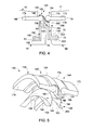
- seal assembly 50 includes a base member 90, a rocker arm 94, and a seal element 97.
- Base member 90 includes a base portion 104 that is mounted to inlet flange 70 in seal mounting member 78.
- Base portion 104 extends to a pivoting member 106 having a substantially circular outer surface 107.
- Pivoting member 106 is pivotally connected to a pivoting element 109 of seal assembly 50.
- Pivoting element 109 includes a substantially circular groove element 111 that is configured to receive pivoting member 106. Pivoting element 109 is coupled to seal element 97 through a cantilevered mounting element 115.
- seal element 97 includes a first seal portion 119 that is coupled to a second seal portion 120 through a connecting member 121.
- First seal portion 119 includes a first seal section 122 and a second seal section 123.
- Second seal section 123 extends into first seal receiving portion 63 while first seal portion 122 seals against outlet flange 62.
- second seal portion 120 includes a first seal section 129 and a second seal section 130.
- Second seal section 130 extends into second seal receiving portion 73 while first seal section 129 seals against inlet flange 70.
- Seal assembly 150 includes a first base member 154 and a second base member 156.
- First base member 150 is mounted to inlet flange 70 in seal mounting member 78 while second base member 156 is mounted to outlet flange 62 in another seal mounting member 160.
- First and second base members 154 and 156 are operatively coupled to a rocker arm 165 and a seal element 168.
- First base member 154 includes a base portion 173 that is mounted to inlet flange 70. Base portion 173 extends to a first pivoting member 174 having a substantially circular outer surface 175. Similarly, base member 156 includes a base portion 179 that is mounted to outlet flange 62. Base portion 179 extends to a second pivoting member 180 having a substantially circular outer surface 181.
- Rocker arm 165 includes a first pivoting element 185 that pivots over second pivoting member 180 and a second pivoting element 186 that pivots or travels over first pivoting member 174. First and second pivoting elements 185 and 186 are connected to a cantilevered mounting element 189 that links rocker arm 165 with seal element 168.
- seal element 168 includes a first seal portion 192 coupled to a second seal portion 194 through a connecting member 196.
- First seal portion 192 includes first and second seal elements 198 and 199.
- Second seal element 199 extends into first seal receiving portion 63 while first seal element 198 seals against outlet flange 62.
- Second seal portion 194 includes first and second seal elements 202 and 203.
- Second seal element 203 extends into second seal receiving portion 73 while first seal element 202 seals against inlet flange 72.
- the exemplary embodiments describe a seal assembly that pivots about a pivoting member to ensure that a seal element remains in contact with mating surfaces despite dimensional changes of adjacent members. That is, thermal expansions and contractions can open an interface region between to mating surfaces.
- the seal assembly in accordance with the exemplary embodiments pivots as one, another, or both of the mating surface undergo dimensional changes. It should also be understood that while described as sealing an interface between a transition piece and a turbine portion of a turbomachine, the seal assembly in accordance with the various aspects of the exemplary embodiment can be used to seal between mating surfaces of other components that undergo dimensional changes.
Landscapes
- Engineering & Computer Science (AREA)
- Mechanical Engineering (AREA)
- General Engineering & Computer Science (AREA)
- Turbine Rotor Nozzle Sealing (AREA)
- Structures Of Non-Positive Displacement Pumps (AREA)
Applications Claiming Priority (1)
| Application Number | Priority Date | Filing Date | Title |
|---|---|---|---|
| US13/213,238 US8888445B2 (en) | 2011-08-19 | 2011-08-19 | Turbomachine seal assembly |
Publications (2)
| Publication Number | Publication Date |
|---|---|
| EP2559860A2 true EP2559860A2 (de) | 2013-02-20 |
| EP2559860A3 EP2559860A3 (de) | 2017-10-11 |
Family
ID=46829634
Family Applications (1)
| Application Number | Title | Priority Date | Filing Date |
|---|---|---|---|
| EP12180002.3A Withdrawn EP2559860A3 (de) | 2011-08-19 | 2012-08-10 | Dichtungsanordnung für Turbomaschinen |
Country Status (3)
| Country | Link |
|---|---|
| US (1) | US8888445B2 (de) |
| EP (1) | EP2559860A3 (de) |
| CN (1) | CN102953770B (de) |
Cited By (1)
| Publication number | Priority date | Publication date | Assignee | Title |
|---|---|---|---|---|
| EP3052788A4 (de) * | 2013-10-02 | 2017-06-21 | United Technologies Corporation | Rezirkulationsdichtung zur verwendung in einem gasturbinenmotor |
Families Citing this family (6)
| Publication number | Priority date | Publication date | Assignee | Title |
|---|---|---|---|---|
| US10077669B2 (en) | 2014-11-26 | 2018-09-18 | United Technologies Corporation | Non-metallic engine case inlet compression seal for a gas turbine engine |
| US20160215701A1 (en) * | 2015-01-22 | 2016-07-28 | General Electric Company | Inner seal for a turbomachine transition piece frame assembly |
| US9587502B2 (en) * | 2015-03-06 | 2017-03-07 | United Technologies Corporation | Sliding compliant seal |
| US10408074B2 (en) * | 2016-04-25 | 2019-09-10 | United Technologies Corporation | Creep resistant axial ring seal |
| GB201614711D0 (en) * | 2016-08-31 | 2016-10-12 | Rolls Royce Plc | Axial flow machine |
| JP6966354B2 (ja) * | 2018-02-28 | 2021-11-17 | 三菱パワー株式会社 | ガスタービン燃焼器 |
Family Cites Families (44)
| Publication number | Priority date | Publication date | Assignee | Title |
|---|---|---|---|---|
| US110549A (en) | 1870-12-27 | Improvement in cotton-presses | ||
| US227148A (en) | 1880-05-04 | T-coupling | ||
| US654257A (en) | 1898-07-23 | 1900-07-24 | Canister Mfg Company | Can-heading machine. |
| US875721A (en) | 1907-03-29 | 1908-01-07 | Nicholas H Mertes | Thill-coupling. |
| US1609952A (en) | 1923-06-30 | 1926-12-07 | Budd Edward G Mfg Co | Detachable upholstery for vehicle bodies |
| US3759038A (en) | 1971-12-09 | 1973-09-18 | Westinghouse Electric Corp | Self aligning combustor and transition structure for a gas turbine |
| US3965066A (en) | 1974-03-15 | 1976-06-22 | General Electric Company | Combustor-turbine nozzle interconnection |
| GB2037380A (en) | 1978-12-21 | 1980-07-09 | Rolls Royce | Seals |
| US4645217A (en) | 1985-11-29 | 1987-02-24 | United Technologies Corporation | Finger seal assembly |
| US4785623A (en) | 1987-12-09 | 1988-11-22 | United Technologies Corporation | Combustor seal and support |
| US5014917A (en) | 1989-11-27 | 1991-05-14 | The United States Of America As Represented By The Administrator Of The National Aeronautics And Space Administration | High-temperature, flexible, thermal barrier seal |
| US5127799A (en) | 1990-12-17 | 1992-07-07 | Allied-Signal Inc. | Interstage coupling seal and method of assembling a gas turbine engine |
| US5125796A (en) | 1991-05-14 | 1992-06-30 | General Electric Company | Transition piece seal spring for a gas turbine |
| US5265412A (en) | 1992-07-28 | 1993-11-30 | General Electric Company | Self-accommodating brush seal for gas turbine combustor |
| US5400586A (en) | 1992-07-28 | 1995-03-28 | General Electric Co. | Self-accommodating brush seal for gas turbine combustor |
| US5333992A (en) | 1993-02-05 | 1994-08-02 | United Technologies Corporation | Coolable outer air seal assembly for a gas turbine engine |
| GB9305012D0 (en) | 1993-03-11 | 1993-04-28 | Rolls Royce Plc | Sealing structures for gas turbine engines |
| GB9304994D0 (en) | 1993-03-11 | 1993-04-28 | Rolls Royce Plc | Improvements in or relating to gas turbine engines |
| US5657998A (en) | 1994-09-19 | 1997-08-19 | General Electric Company | Gas-path leakage seal for a gas turbine |
| JPH09195799A (ja) | 1996-01-17 | 1997-07-29 | Mitsubishi Heavy Ind Ltd | 燃焼器のスプリングシール装置 |
| US5630700A (en) | 1996-04-26 | 1997-05-20 | General Electric Company | Floating vane turbine nozzle |
| DE19618475B4 (de) * | 1996-05-08 | 2005-10-20 | Mtu Aero Engines Gmbh | Bürstendichtung |
| JP3854341B2 (ja) * | 1996-08-02 | 2006-12-06 | 三菱重工業株式会社 | ガスタービン冷却用蒸気給排部構造のシール装置 |
| WO2002027148A1 (en) | 2000-09-28 | 2002-04-04 | Siemens Westinghouse Power Corporation | Flexible interlocking combustor transition seal |
| US20020121744A1 (en) | 2001-03-05 | 2002-09-05 | General Electric Company | Low leakage flexible cloth seals for turbine combustors |
| US6547257B2 (en) | 2001-05-04 | 2003-04-15 | General Electric Company | Combination transition piece floating cloth seal and stage 1 turbine nozzle flexible sealing element |
| US7080513B2 (en) | 2001-08-04 | 2006-07-25 | Siemens Aktiengesellschaft | Seal element for sealing a gap and combustion turbine having a seal element |
| JP3600912B2 (ja) | 2001-09-12 | 2004-12-15 | 川崎重工業株式会社 | 燃焼器ライナのシール構造 |
| US6637752B2 (en) | 2001-12-28 | 2003-10-28 | General Electric Company | Supplemental seal for the chordal hinge seal in a gas turbine |
| US6918598B2 (en) * | 2002-04-02 | 2005-07-19 | Honeywell International, Inc. | Hot air seal |
| US6675584B1 (en) | 2002-08-15 | 2004-01-13 | Power Systems Mfg, Llc | Coated seal article used in turbine engines |
| US6792763B2 (en) * | 2002-08-15 | 2004-09-21 | Power Systems Mfg., Llc | Coated seal article with multiple coatings |
| US6860108B2 (en) | 2003-01-22 | 2005-03-01 | Mitsubishi Heavy Industries, Ltd. | Gas turbine tail tube seal and gas turbine using the same |
| US6895757B2 (en) | 2003-02-10 | 2005-05-24 | General Electric Company | Sealing assembly for the aft end of a ceramic matrix composite liner in a gas turbine engine combustor |
| JP3795036B2 (ja) | 2003-03-14 | 2006-07-12 | 三菱重工業株式会社 | タービン尾筒のシール構造およびシール装置 |
| FR2860039B1 (fr) * | 2003-09-19 | 2005-11-25 | Snecma Moteurs | Realisation de l'etancheite dans un turboreacteur pour le prelevement cabine par joints double sens a lamelles |
| JP2005337122A (ja) | 2004-05-27 | 2005-12-08 | Ishikawajima Harima Heavy Ind Co Ltd | ガスシール装置 |
| US7007482B2 (en) | 2004-05-28 | 2006-03-07 | Power Systems Mfg., Llc | Combustion liner seal with heat transfer augmentation |
| US7052234B2 (en) | 2004-06-23 | 2006-05-30 | General Electric Company | Turbine vane collar seal |
| GB2417528B (en) | 2004-08-23 | 2008-08-06 | Alstom Technology Ltd | Improved rope seal for gas turbine engines |
| WO2006038328A1 (ja) | 2004-09-30 | 2006-04-13 | Eagle Engineering Aerospace Co., Ltd. | シール部品 |
| US7246995B2 (en) | 2004-12-10 | 2007-07-24 | Siemens Power Generation, Inc. | Seal usable between a transition and a turbine vane assembly in a turbine engine |
| US7524167B2 (en) | 2006-05-04 | 2009-04-28 | Siemens Energy, Inc. | Combustor spring clip seal system |
| GB0905815D0 (en) * | 2009-04-06 | 2009-05-20 | Rolls Royce Plc | A sealing assembly |
-
2011
- 2011-08-19 US US13/213,238 patent/US8888445B2/en not_active Expired - Fee Related
-
2012
- 2012-08-10 EP EP12180002.3A patent/EP2559860A3/de not_active Withdrawn
- 2012-08-16 CN CN201210293165.3A patent/CN102953770B/zh not_active Expired - Fee Related
Non-Patent Citations (1)
| Title |
|---|
| None |
Cited By (2)
| Publication number | Priority date | Publication date | Assignee | Title |
|---|---|---|---|---|
| EP3052788A4 (de) * | 2013-10-02 | 2017-06-21 | United Technologies Corporation | Rezirkulationsdichtung zur verwendung in einem gasturbinenmotor |
| US10215045B2 (en) | 2013-10-02 | 2019-02-26 | United Technologies Corporation | Recirculation seal for use in a gas turbine engine |
Also Published As
| Publication number | Publication date |
|---|---|
| CN102953770A (zh) | 2013-03-06 |
| US20130045090A1 (en) | 2013-02-21 |
| US8888445B2 (en) | 2014-11-18 |
| CN102953770B (zh) | 2015-09-23 |
| EP2559860A3 (de) | 2017-10-11 |
Similar Documents
| Publication | Publication Date | Title |
|---|---|---|
| EP2564032B1 (de) | Komponente einer turbine mit lamellendichtungen und verfahren zur abdichtung gegen leckagen zwischen einer schaufel und einem trägerelement | |
| JP5905676B2 (ja) | トランジションピースのシール用シム | |
| US8888445B2 (en) | Turbomachine seal assembly | |
| US8678754B2 (en) | Assembly for preventing fluid flow | |
| EP2587002B1 (de) | Turbomaschine mit einer Anordnung zum Abdichten des inneren Turbinengehäuses gegen das äußere Turbinengehäuse und zugehöriges Verfahren | |
| JP5302979B2 (ja) | タービン・エンジン用高温シール | |
| EP2592231B1 (de) | Flexible Metalldichtung für einen Überleitkanal in einem Turbinensystem | |
| US20090169369A1 (en) | Turbine nozzle segment and assembly | |
| US9963989B2 (en) | Gas turbine engine vane-to-transition duct seal | |
| EP2642078A2 (de) | System und Verfahren zur Rückführung eines durch eine Gasturbine strömenden Heißgases | |
| JP2007513281A (ja) | 燃焼器壁とノズルプラットフォームとの間の褶動ジョイント | |
| KR20160064018A (ko) | 제 1 스테이지 터빈 베인 장치 | |
| US9175573B2 (en) | Dovetail attachment seal for a turbomachine | |
| CN102926972B (zh) | 用于涡轮机中的流动热气的密封组件和方法 | |
| CN103195497A (zh) | 用于燃气涡轮机的喷嘴及密封件承载部 | |
| CN103233784B (zh) | 涡轮喷嘴冷却组件 | |
| US11802493B2 (en) | Outlet guide vane assembly in gas turbine engine | |
| EP2617948A2 (de) | Dichtung in der Nähe des Durchflusswegs für eine Turbomaschine |
Legal Events
| Date | Code | Title | Description |
|---|---|---|---|
| PUAI | Public reference made under article 153(3) epc to a published international application that has entered the european phase |
Free format text: ORIGINAL CODE: 0009012 |
|
| AK | Designated contracting states |
Kind code of ref document: A2 Designated state(s): AL AT BE BG CH CY CZ DE DK EE ES FI FR GB GR HR HU IE IS IT LI LT LU LV MC MK MT NL NO PL PT RO RS SE SI SK SM TR |
|
| AX | Request for extension of the european patent |
Extension state: BA ME |
|
| PUAL | Search report despatched |
Free format text: ORIGINAL CODE: 0009013 |
|
| AK | Designated contracting states |
Kind code of ref document: A3 Designated state(s): AL AT BE BG CH CY CZ DE DK EE ES FI FR GB GR HR HU IE IS IT LI LT LU LV MC MK MT NL NO PL PT RO RS SE SI SK SM TR |
|
| AX | Request for extension of the european patent |
Extension state: BA ME |
|
| RIC1 | Information provided on ipc code assigned before grant |
Ipc: F01D 11/00 20060101AFI20170907BHEP Ipc: F01D 9/02 20060101ALI20170907BHEP |
|
| STAA | Information on the status of an ep patent application or granted ep patent |
Free format text: STATUS: THE APPLICATION IS DEEMED TO BE WITHDRAWN |
|
| 18D | Application deemed to be withdrawn |
Effective date: 20180301 |