EP2559880A2 - Système de moteur et véhicule - Google Patents
Système de moteur et véhicule Download PDFInfo
- Publication number
- EP2559880A2 EP2559880A2 EP12180650A EP12180650A EP2559880A2 EP 2559880 A2 EP2559880 A2 EP 2559880A2 EP 12180650 A EP12180650 A EP 12180650A EP 12180650 A EP12180650 A EP 12180650A EP 2559880 A2 EP2559880 A2 EP 2559880A2
- Authority
- EP
- European Patent Office
- Prior art keywords
- engine
- supercharger
- compressor
- load
- vehicle
- Prior art date
- Legal status (The legal status is an assumption and is not a legal conclusion. Google has not performed a legal analysis and makes no representation as to the accuracy of the status listed.)
- Withdrawn
Links
- 230000006835 compression Effects 0.000 claims abstract description 8
- 238000007906 compression Methods 0.000 claims abstract description 8
- 238000002485 combustion reaction Methods 0.000 claims abstract description 5
- 238000000034 method Methods 0.000 claims description 29
- 230000005540 biological transmission Effects 0.000 claims description 6
- 238000011144 upstream manufacturing Methods 0.000 claims description 3
- 230000009467 reduction Effects 0.000 claims description 2
- 239000012530 fluid Substances 0.000 description 4
- 239000000446 fuel Substances 0.000 description 4
- 239000003381 stabilizer Substances 0.000 description 4
- 230000001052 transient effect Effects 0.000 description 4
- 239000000779 smoke Substances 0.000 description 3
- 230000004913 activation Effects 0.000 description 2
- 230000008901 benefit Effects 0.000 description 1
- 238000001816 cooling Methods 0.000 description 1
- 230000006872 improvement Effects 0.000 description 1
- 239000000463 material Substances 0.000 description 1
- 230000004044 response Effects 0.000 description 1
Images


Classifications
-
- F—MECHANICAL ENGINEERING; LIGHTING; HEATING; WEAPONS; BLASTING
- F02—COMBUSTION ENGINES; HOT-GAS OR COMBUSTION-PRODUCT ENGINE PLANTS
- F02B—INTERNAL-COMBUSTION PISTON ENGINES; COMBUSTION ENGINES IN GENERAL
- F02B37/00—Engines characterised by provision of pumps driven at least for part of the time by exhaust
- F02B37/04—Engines with exhaust drive and other drive of pumps, e.g. with exhaust-driven pump and mechanically-driven second pump
-
- F—MECHANICAL ENGINEERING; LIGHTING; HEATING; WEAPONS; BLASTING
- F02—COMBUSTION ENGINES; HOT-GAS OR COMBUSTION-PRODUCT ENGINE PLANTS
- F02B—INTERNAL-COMBUSTION PISTON ENGINES; COMBUSTION ENGINES IN GENERAL
- F02B37/00—Engines characterised by provision of pumps driven at least for part of the time by exhaust
- F02B37/12—Control of the pumps
-
- B—PERFORMING OPERATIONS; TRANSPORTING
- B66—HOISTING; LIFTING; HAULING
- B66F—HOISTING, LIFTING, HAULING OR PUSHING, NOT OTHERWISE PROVIDED FOR, e.g. DEVICES WHICH APPLY A LIFTING OR PUSHING FORCE DIRECTLY TO THE SURFACE OF A LOAD
- B66F9/00—Devices for lifting or lowering bulky or heavy goods for loading or unloading purposes
- B66F9/06—Devices for lifting or lowering bulky or heavy goods for loading or unloading purposes movable, with their loads, on wheels or the like, e.g. fork-lift trucks
- B66F9/065—Devices for lifting or lowering bulky or heavy goods for loading or unloading purposes movable, with their loads, on wheels or the like, e.g. fork-lift trucks non-masted
-
- B—PERFORMING OPERATIONS; TRANSPORTING
- B66—HOISTING; LIFTING; HAULING
- B66F—HOISTING, LIFTING, HAULING OR PUSHING, NOT OTHERWISE PROVIDED FOR, e.g. DEVICES WHICH APPLY A LIFTING OR PUSHING FORCE DIRECTLY TO THE SURFACE OF A LOAD
- B66F9/00—Devices for lifting or lowering bulky or heavy goods for loading or unloading purposes
- B66F9/06—Devices for lifting or lowering bulky or heavy goods for loading or unloading purposes movable, with their loads, on wheels or the like, e.g. fork-lift trucks
- B66F9/075—Constructional features or details
- B66F9/07572—Propulsion arrangements
-
- E—FIXED CONSTRUCTIONS
- E02—HYDRAULIC ENGINEERING; FOUNDATIONS; SOIL SHIFTING
- E02F—DREDGING; SOIL-SHIFTING
- E02F9/00—Component parts of dredgers or soil-shifting machines, not restricted to one of the kinds covered by groups E02F3/00 - E02F7/00
- E02F9/20—Drives; Control devices
- E02F9/2058—Electric or electro-mechanical or mechanical control devices of vehicle sub-units
- E02F9/2062—Control of propulsion units
- E02F9/2066—Control of propulsion units of the type combustion engines
-
- E—FIXED CONSTRUCTIONS
- E02—HYDRAULIC ENGINEERING; FOUNDATIONS; SOIL SHIFTING
- E02F—DREDGING; SOIL-SHIFTING
- E02F9/00—Component parts of dredgers or soil-shifting machines, not restricted to one of the kinds covered by groups E02F3/00 - E02F7/00
- E02F9/20—Drives; Control devices
- E02F9/2058—Electric or electro-mechanical or mechanical control devices of vehicle sub-units
- E02F9/2091—Control of energy storage means for electrical energy, e.g. battery or capacitors
-
- E—FIXED CONSTRUCTIONS
- E02—HYDRAULIC ENGINEERING; FOUNDATIONS; SOIL SHIFTING
- E02F—DREDGING; SOIL-SHIFTING
- E02F9/00—Component parts of dredgers or soil-shifting machines, not restricted to one of the kinds covered by groups E02F3/00 - E02F7/00
- E02F9/20—Drives; Control devices
- E02F9/2058—Electric or electro-mechanical or mechanical control devices of vehicle sub-units
- E02F9/2095—Control of electric, electro-mechanical or mechanical equipment not otherwise provided for, e.g. ventilators, electro-driven fans
-
- E—FIXED CONSTRUCTIONS
- E02—HYDRAULIC ENGINEERING; FOUNDATIONS; SOIL SHIFTING
- E02F—DREDGING; SOIL-SHIFTING
- E02F9/00—Component parts of dredgers or soil-shifting machines, not restricted to one of the kinds covered by groups E02F3/00 - E02F7/00
- E02F9/20—Drives; Control devices
- E02F9/22—Hydraulic or pneumatic drives
- E02F9/2246—Control of prime movers, e.g. depending on the hydraulic load of work tools
-
- F—MECHANICAL ENGINEERING; LIGHTING; HEATING; WEAPONS; BLASTING
- F02—COMBUSTION ENGINES; HOT-GAS OR COMBUSTION-PRODUCT ENGINE PLANTS
- F02B—INTERNAL-COMBUSTION PISTON ENGINES; COMBUSTION ENGINES IN GENERAL
- F02B39/00—Component parts, details, or accessories relating to, driven charging or scavenging pumps, not provided for in groups F02B33/00 - F02B37/00
- F02B39/005—Cooling of pump drives
-
- F—MECHANICAL ENGINEERING; LIGHTING; HEATING; WEAPONS; BLASTING
- F02—COMBUSTION ENGINES; HOT-GAS OR COMBUSTION-PRODUCT ENGINE PLANTS
- F02B—INTERNAL-COMBUSTION PISTON ENGINES; COMBUSTION ENGINES IN GENERAL
- F02B39/00—Component parts, details, or accessories relating to, driven charging or scavenging pumps, not provided for in groups F02B33/00 - F02B37/00
- F02B39/02—Drives of pumps; Varying pump drive gear ratio
- F02B39/08—Non-mechanical drives, e.g. fluid drives having variable gear ratio
- F02B39/10—Non-mechanical drives, e.g. fluid drives having variable gear ratio electric
-
- F—MECHANICAL ENGINEERING; LIGHTING; HEATING; WEAPONS; BLASTING
- F02—COMBUSTION ENGINES; HOT-GAS OR COMBUSTION-PRODUCT ENGINE PLANTS
- F02D—CONTROLLING COMBUSTION ENGINES
- F02D23/00—Controlling engines characterised by their being supercharged
-
- F—MECHANICAL ENGINEERING; LIGHTING; HEATING; WEAPONS; BLASTING
- F02—COMBUSTION ENGINES; HOT-GAS OR COMBUSTION-PRODUCT ENGINE PLANTS
- F02D—CONTROLLING COMBUSTION ENGINES
- F02D41/00—Electrical control of supply of combustible mixture or its constituents
- F02D41/0002—Controlling intake air
- F02D41/0007—Controlling intake air for control of turbo-charged or super-charged engines
-
- Y—GENERAL TAGGING OF NEW TECHNOLOGICAL DEVELOPMENTS; GENERAL TAGGING OF CROSS-SECTIONAL TECHNOLOGIES SPANNING OVER SEVERAL SECTIONS OF THE IPC; TECHNICAL SUBJECTS COVERED BY FORMER USPC CROSS-REFERENCE ART COLLECTIONS [XRACs] AND DIGESTS
- Y02—TECHNOLOGIES OR APPLICATIONS FOR MITIGATION OR ADAPTATION AGAINST CLIMATE CHANGE
- Y02T—CLIMATE CHANGE MITIGATION TECHNOLOGIES RELATED TO TRANSPORTATION
- Y02T10/00—Road transport of goods or passengers
- Y02T10/10—Internal combustion engine [ICE] based vehicles
- Y02T10/12—Improving ICE efficiencies
Definitions
- the present invention relates to an engine system particularly for use on a earth moving machine or a load handling machine.
- Earth moving machines and load handling machines have a particular transient engine power requirement.
- the machine when the front shovel of a back hoe loading machine is being used to move loose material such as a pile of stones, the machine is driven forwards into the pile of stones with the shovel lowered and as the shovel progressively fills the machine is driven further into the pile and the shovel is progressively turned upwardly and is also lifted.
- the time taken to fill the shovel is relatively short, of the order of a few seconds.
- the engine will typically be working at maximum power since it is both driving the transmission to move the machine forwards and also driving the hydraulic system to both turn (crowd) and lift the shovel. Accordingly, there is a high power requirement for a relatively short amount of time.
- the machine will then be reversed out of the pile with the full shovel.
- the operator will typically not reverse in a straight line, rather the machine will be turning during reversing.
- the full shovel will be held relatively low so as to ensure the machine does not roll over during reversing and turning.
- the machine will then be driven forward whilst the shovel is being raised to full height so that the load can be emptied for example into a lorry for onward transportation.
- the machine will then be driven forward whilst the shovel is being raised to full height so that the load can be emptied for example into a lorry for onward transportation.
- this high power requirement lasts for a relatively short time, of the order of a few seconds.
- an engine system including a compression ignition internal combustion engine, a turbo charger having a turbo charger turbine coupled to a turbo charger compressor, an electric supercharger having an electric motor coupled to a supercharger compressor, the electric supercharger being operable to selective supply pressurised air to an inlet of the turbo charger compressor, and a bypass duct for selectively supplying air to the inlet of the turbo charger compressor.
- an electric supercharger it can be operated for relatively short periods of time (for example for a few seconds) thereby temporarily increasing the maximum power the engine can produce.
- the electric supercharger can be disabled and the engine can be fed via the bypass duct.
- the bypass duct may include a valve for selectively closing bypass duct.
- the valve may be an automatic valve which closes when an air pressure on the downstream side of the valve is higher than an air pressure on the upstream side of the valve.
- the engine system may include an air intake system for selectively supplying air to the bypass duct and to an inlet of the supercharger compressor.
- the air intake system may include a cooler for the electric motor, the cooler being fed by air passing through the air intake system.
- the engine system may include a battery for supplying power to the electric motor, an engine driven recharging system for recharging the battery and a control system for reducing the power consumed by the recharging system when the electric supercharger is being operated.
- the control system may include a ballast system.
- the engine system may be operated by a method including the steps of:
- such a method is particularly suitable for use in an earth moving machine or in a load handling machine which require a high engine power for relatively short periods of time due to operating both the transmission and the hydraulic system.
- the engine system may be operated by a method including the steps of:
- such a method is particularly suitable for use in an earth moving machine or in a load handling machine which require a high engine power for relatively short periods of time due to operating both the transmission and the hydraulic system.
- the engine system may be operated such that the electric motor only powers the supercharger compressor for periods of less than 10 seconds, preferably for periods less than 7 seconds, preferably for periods less than 5 seconds.
- the engine system may be incorporated into a vehicle.
- the vehicle may be a load handling vehicle.
- the vehicle may be a hydraulic transmission and/or a load handling apparatus having a hydraulic actuator.
- a method of moving a load including the steps of providing a load handling vehicle having an engine system as defined in the first aspect of the present invention, ground engaging means operable to move the vehicle and being selectively powered by the engine system, and a load handling apparatus being moveable relative to a chassis of the vehicle by an actuator, the actuator being powered by the engine to at least lift a load, the method further including the steps of simultaneously:
- the engines able to produce more power when there is a high power demand, i.e. when it is required to both move the vehicle and lift the load.
- the load handling vehicle may move forwards when the steps carried out simultaneously are performed.
- the engine can generate more power when the vehicle picks up a load, for example when it drives forward to push a shovel into a pile of loose stones or the like, or when it drives forwards to pick up a load on a set of lifting forks.
- the method may include the further step of subsequently simultaneously reversing the load handling vehicle whilst the electric supercharger is not operating.
- the method may include the further step of subsequently simultaneously powering the ground engaging means by the engine to move the load handling vehicle forwards, powering the actuator by the engine to lift the load and using the electric supercharger to supply pressurised air to the inlet of the turbo charger compressor.
- the supercharger can be used to increase the power delivered by the engine.
- the method may include the step of subsequently releasing the load.
- the method may include the further step of subsequently simultaneously reversing the load handling vehicle whilst the electric supercharger is not operating.
- the method may include the further step of subsequently simultaneously powering the ground engaging means by the engine to move the load handling vehicle forwards, powering the actuator by the engine to lift a further load and using the electric supercharger to supply pressurised air to the inlet of the turbo charger compressor.
- the method may include the further step of subsequently simultaneously reversing the load handling vehicle whilst the electric supercharger is not operating.
- the method may include the further step of subsequently simultaneously powering the ground engaging means by the engine to move the load handling vehicle forwards, powering the actuator by the engine to lift the load and using the electric supercharger to supply pressurised air to the inlet of the turbo charger compressor.
- the method may include the further step of subsequently releasing said further load adjacent said load.
- the cycle time can be reduced without the need for a larger more powerful engine.
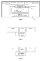
- a vehicle 10 including an engine system 12.
- the engine system includes a compression ignition internal combustion engine 14, for example a diesel engine.
- the engine system has an air intake system 16, an exhaust system 18 and an electrical system 20.
- the air intake system 16 includes an air filter 30, an electric supercharger 32, a turbo charger 34, a charge air cooler 36 and an inlet manifold 38.
- the exhaust system includes an exhaust manifold 40, the turbocharger 34 and an exhaust pipe 42.
- the electrical system 20 includes an alternator 50, a ballast system 52, the electric supercharger 32 and a vehicle battery 54 (typically a 12 volt or 24 volt battery).
- the turbo charger has a turbocharger turbine 60 coupled to a turbocharger compressor 62.
- the electric supercharger has an electric motor 64 coupled to a supercharger compressor 66.
- the electric motor 64 is contained within a housing 68.
- An air duct 70 connects the air filter 30 to the housing 68.
- An air duct 71 connects the housing to a first air duct junction 72.
- An air duct 73 connects the first air duct junction 72 to an intake 66i of the supercharger compressor.
- An air duct 74 connects an outlet 66o of the supercharger compressor 66 to a second air duct junction 75.
- a bypass air duct 76 connects the first air duct junction 72 to the second air duct junction 75.
- a valve 77 is positioned in the bypass air duct 76.
- An air duct 78 connects the second air duct junction 75 to an inlet 62i of the turbocharger compressor.
- An air duct 79 connects an outlet 62o of the turbocharger compressor with an inlet to the charge air cooler 36.
- An air duct 80 connects an outlet of the charge air cooler with the inlet manifold 38.
- the electric motor 64 can be selectively driven by the vehicle battery 54 as will be further described below.
- the vehicle battery 54 is selectively recharged by the alternator 50 operating via the ballast system 52.
- air fed into the inlet manifold 38 will only have one stage of compression, i.e. it will only have been compressed by the turbocharger compressor 62.
- the ballast system 52 disables recharging of the battery from the alternator 50 thereby reducing the power drain the alternator has on the engine.
- the battery may be sized to be capable of driving the electric motor for this time period. Once the peak engine power requirement has ceased, then the alternator can recharge the battery in readiness for the next peak engine power requirement.
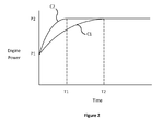
- Figure 2 shows the transient response of an engine according to the present invention and an equivalent engine without a supercharger.
- Each engine is assumed to be running at a relatively low speed and relatively low power and at time t0 a maximum power is demanded (e.g. an operator pushes the accelerator pedal to the floor).
- Curve C1 shows operation of an engine without an electric supercharger. Thus it takes time t2 to increase the power from P1 to P2.
- Curve C2 shows how the power increases when the electric supercharger of the present invention is used. As can be seen it takes time t1 to increase the power from P1 to P2.
- Curve C1 is the maximum increase in power with respect to time that can be achieved whilst maintaining acceptable smoke levels.
- the advantage of using the electric supercharger in C2 is that the power can be increased faster whilst still maintaining acceptable smoke levels.
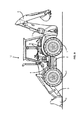
- FIG. 9 shows vehicle 10 which, in this example is a load handling vehicle in the form of a back hoe loader.
- the vehicle includes ground engaging means in the form of wheels 1, in this case two front wheels and two rear wheels.
- the vehicle includes a chassis 2 upon which is mounted a load handling apparatus in the form of a front loader arm 3.
- the front loader arm 3 is moveable relative to the chassis 2 by operation of an actuator 4, in this case a hydraulic ram.
- Mounted at the front of the load handling apparatus is a load handling implement in the form of a shovel 5.
- At the rear of the machine there is a load handling implement in the form of a back hoe 6.
- Stabilisers 7 are shown in a raised position in figure 9 when the shovel 5 is being used to move loads by, for example moving the vehicle forwards and backwards. Stabilisers 7 can be lowered to engage the ground to improve the stability of the machine when it is stationary and the back hoe 6 is in use.
- Shovel 5 can be replaced with an alternative load handling implement, for example a set of loading forks.
- FIG 10 shows an alternative machine 10', which in this case is a telehandler.
- the telehandler includes wheels 1', in this case two front wheels and two rear wheels.
- the vehicle includes a chassis 2' upon which is mounted a load handling apparatus in the form of a loader arm 3'.
- the loader arm 3' is pivotally mounted relative to the chassis 2' at pivot 3A' which is proximate the rear of the machine.
- the loader arm 3' lies substantially horizontally with a front end thereof proximate the front of the telehandler.
- the loader arm 3' is moved relative to the chassis 2' by operation of an actuator 4', in this case a hydraulic ram.
- a load handling implement in the form of a set of forks 5'.
- the loader arm 3' is a telescopic arm.
- Stabilisers 7' can be lowered so as to engage the ground when the telehandler is moving loads whilst the chassis is stationary.
- the stabilisers 7' will be in a raised position.
- Loading forks 5' can be replaced with an alternative load handling implement, for example a loading shovel.
- a control system may monitor the position of the accelerator pedal (which indicates the power or speed demand requirement), the engine speed, the engine torque and the battery voltage.
- a control processor 91 can then determine whether or not the supercharger should be activated. Upon activation the control processor can determine the speed of the electric motor which drives the supercharger compressor and can also determine the activation time.
- valve 77 is an automatic valve which closes when an air pressure on the downstream side of the valve (i.e. on the side of the valve closest to the second air duct junction 75) is higher than an air pressure on the upstream side of the valve, i.e. on a side of the valve closest to the first air duct junction 72. This pressure differential will only occur when the electric supercharger is activated.
- control system 90 may operate to close the valve 77.
- the electric motor 64 is contained within housing 66 through which air passes.
- the intake air acts to cool the electric motor, since the intake air is passing over the motor, thereby cooling it.
- the intake system therefore includes a cooler.
- the ballast system operates to reduce the demand on the alternator when a relatively high demand is being placed on the battery 54.
- the ballast unit increases the resistance between the alternator and battery which lowers the voltage when the electric motor operates. This means that the power demand for the motor comes primarily from the battery and not the alternator.
- the system used to recharge the battery need not necessarily be an alternator, any type of engine driven recharging system would be appropriate.
- a ballast system any type of control system which reduces the power consumed by the recharging system when the electric supercharger is being operated would be suitable.
- dedicated electrical switches could be used to isolate a recharging system.
- a clutch or the like could be used to mechanically uncouple the charging system from the engine drive.
- the present invention is particularly useful in earth moving machines and in load handling machines.
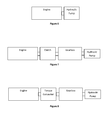
- the engine is required to at least drive a hydraulic pump which supplies pressurised fluid to ancillary equipment.
- the engine drives both a clutch and a hydraulic pump with the clutch driving a gear box and the gear box driving the wheels of the vehicle.
- the hydraulic pump can be used to supply pressurised oil to ancillary equipment such as hydraulic rams for loader buckets, back hoes, lifting forks and the like.
- figure 5 shows the engine driving a torque converter which in turn drives a gear box, the engine also driving a hydraulic pump which supplies pressurised fluid to ancillary equipment.
- Figure 6 shows the engine driving a hydraulic pump with the hydraulic pump supplying pressurised oil to hydraulic motors for moving the machine and also for supplying pressurised hydraulic fluid to ancillary equipment such as hydraulic rams which operate loader shovels, back hoes and the like.
- Figure 7 shows an engine driving a gear box via a clutch with the hydraulic pump being driven by the gear box.
- the hydraulic pump supplies pressurised fluid to ancillary equipment.
- Figure 8 is similar to figure 7 except the gear box is driven via a torque converter rather than a clutch.
- the invention can be used with load handling machines such as back hand loaders and telehandlers.
- load handling machines such as back hand loaders and telehandlers.
- the invention is equally applicable to other types of load handling machines.
- the invention is particularly applicable to load handling machines which can move a load by virtue of moving the machine over the ground e.g. by ground engaging wheels, tracks or the like.
- the invention can be used with load handling implements such as a loading shovel or a set of forks.
- load handling implements such as a loading shovel or a set of forks.
- the invention can equally be used with other types of load handling implements.
- figure 1 shows a schematic view of vehicle 10 which, from figure 9 , can be seen to be a back hand loader.
- vehicle 10 of figure 1 can be any type of load handling machine, such as the machine shown in figure 10 or any other type of load handling machine.
- Equally figures 3, 4, 5 , 6, 7 and 8 can be used with loading machine 10 shown in figure 9 , loading machine 10' shown in figure 10 or any other type of loading machine.
Landscapes
- Engineering & Computer Science (AREA)
- General Engineering & Computer Science (AREA)
- Mechanical Engineering (AREA)
- Chemical & Material Sciences (AREA)
- Combustion & Propulsion (AREA)
- Structural Engineering (AREA)
- Civil Engineering (AREA)
- Transportation (AREA)
- Mining & Mineral Resources (AREA)
- Life Sciences & Earth Sciences (AREA)
- Geology (AREA)
- Power Engineering (AREA)
- Supercharger (AREA)
Applications Claiming Priority (1)
| Application Number | Priority Date | Filing Date | Title |
|---|---|---|---|
| GB1114312.0A GB2493915A (en) | 2011-08-19 | 2011-08-19 | Internal combustion engine with turbocharger, supercharger and supercharger bypass |
Publications (2)
| Publication Number | Publication Date |
|---|---|
| EP2559880A2 true EP2559880A2 (fr) | 2013-02-20 |
| EP2559880A3 EP2559880A3 (fr) | 2017-04-26 |
Family
ID=44800559
Family Applications (1)
| Application Number | Title | Priority Date | Filing Date |
|---|---|---|---|
| EP12180650.9A Withdrawn EP2559880A3 (fr) | 2011-08-19 | 2012-08-16 | Système de moteur et véhicule |
Country Status (2)
| Country | Link |
|---|---|
| EP (1) | EP2559880A3 (fr) |
| GB (1) | GB2493915A (fr) |
Cited By (1)
| Publication number | Priority date | Publication date | Assignee | Title |
|---|---|---|---|---|
| US20160348632A1 (en) * | 2013-12-19 | 2016-12-01 | Valeo Systemes De Controle Moteur | Assembly comprising a heat engine and an electrical compressor |
Families Citing this family (1)
| Publication number | Priority date | Publication date | Assignee | Title |
|---|---|---|---|---|
| KR102777553B1 (ko) * | 2019-12-05 | 2025-03-06 | 현대자동차 주식회사 | 하이브리드 차량 |
Family Cites Families (6)
| Publication number | Priority date | Publication date | Assignee | Title |
|---|---|---|---|---|
| US6029452A (en) * | 1995-11-15 | 2000-02-29 | Turbodyne Systems, Inc. | Charge air systems for four-cycle internal combustion engines |
| US5771868A (en) * | 1997-07-03 | 1998-06-30 | Turbodyne Systems, Inc. | Turbocharging systems for internal combustion engines |
| DE10202146B4 (de) * | 2002-01-21 | 2005-12-22 | Siemens Ag | Verfahren zur Ansteuerung eines elektrisch angetriebenen Verdichters |
| JP3951951B2 (ja) * | 2003-04-03 | 2007-08-01 | トヨタ自動車株式会社 | 内燃機関の制御装置 |
| JP4389739B2 (ja) * | 2004-09-29 | 2009-12-24 | 三菱自動車工業株式会社 | 過給機付き内燃機関 |
| FI121800B (fi) * | 2008-01-10 | 2011-04-15 | Waertsilae Finland Oy | Mäntämoottorin ahdinjärjestely |
-
2011
- 2011-08-19 GB GB1114312.0A patent/GB2493915A/en not_active Withdrawn
-
2012
- 2012-08-16 EP EP12180650.9A patent/EP2559880A3/fr not_active Withdrawn
Non-Patent Citations (1)
| Title |
|---|
| None |
Cited By (1)
| Publication number | Priority date | Publication date | Assignee | Title |
|---|---|---|---|---|
| US20160348632A1 (en) * | 2013-12-19 | 2016-12-01 | Valeo Systemes De Controle Moteur | Assembly comprising a heat engine and an electrical compressor |
Also Published As
| Publication number | Publication date |
|---|---|
| GB201114312D0 (en) | 2011-10-05 |
| EP2559880A3 (fr) | 2017-04-26 |
| GB2493915A (en) | 2013-02-27 |
Similar Documents
| Publication | Publication Date | Title |
|---|---|---|
| US7658250B2 (en) | Energy storage and recovery for a tracked machine | |
| EP1967486B1 (fr) | Plate-forme de travail mobile | |
| US9989042B2 (en) | Propel circuit and work circuit combinations for a work machine | |
| EP2100787B1 (fr) | Machine de travail avec unité d'alimentation auxiliaire et gestion d'alimentation intelligente | |
| RU2394701C2 (ru) | Электрическая силовая передача для рабочей машины | |
| US7779616B2 (en) | Vehicle with electric hybrid powering of external loads and engine-off capability | |
| RU2514412C2 (ru) | Сельскохозяйственная машина (варианты) и способ выполнения уборочных операций | |
| US8321094B2 (en) | Engine control system for construction machine | |
| US8087900B2 (en) | Agricultural harvester with propulsion load shifting between dual engines | |
| US10557481B2 (en) | Hydraulic system including a kinetic energy storage device | |
| US11572824B2 (en) | Electrified engine boost components for mitigating engine stalling in a work vehicle | |
| JP2009511787A (ja) | 作業機械 | |
| CN103180520B (zh) | 动力传动装置 | |
| CN103635636A (zh) | 用于控制具有电气和/或液压装置的机器中的动力的系统 | |
| US7974757B2 (en) | Agricultural harvester with dual engine failure power transfer system | |
| JP2007071197A (ja) | ハイブリッド型油圧作業機 | |
| CN114763700B (zh) | 具有牵引马达驱动液压回路的传动系统及其控制方法 | |
| US20080223631A1 (en) | Working Machine | |
| CN112282944B (zh) | 减少装载机、挖掘机、反铲装载机等中的燃料消耗的方法 | |
| CN103620126A (zh) | 用于将辅助动力提供给动力传动系和液压回路的液压系统 | |
| WO2011099326A1 (fr) | Moteur | |
| EP2559880A2 (fr) | Système de moteur et véhicule | |
| JP7512232B2 (ja) | 作業機 |
Legal Events
| Date | Code | Title | Description |
|---|---|---|---|
| PUAI | Public reference made under article 153(3) epc to a published international application that has entered the european phase |
Free format text: ORIGINAL CODE: 0009012 |
|
| AK | Designated contracting states |
Kind code of ref document: A2 Designated state(s): AL AT BE BG CH CY CZ DE DK EE ES FI FR GB GR HR HU IE IS IT LI LT LU LV MC MK MT NL NO PL PT RO RS SE SI SK SM TR |
|
| AX | Request for extension of the european patent |
Extension state: BA ME |
|
| PUAL | Search report despatched |
Free format text: ORIGINAL CODE: 0009013 |
|
| AK | Designated contracting states |
Kind code of ref document: A3 Designated state(s): AL AT BE BG CH CY CZ DE DK EE ES FI FR GB GR HR HU IE IS IT LI LT LU LV MC MK MT NL NO PL PT RO RS SE SI SK SM TR |
|
| AX | Request for extension of the european patent |
Extension state: BA ME |
|
| RIC1 | Information provided on ipc code assigned before grant |
Ipc: F02B 39/00 20060101ALI20170320BHEP Ipc: F02B 37/04 20060101AFI20170320BHEP Ipc: E02F 9/20 20060101ALI20170320BHEP Ipc: B66F 9/075 20060101ALI20170320BHEP Ipc: B66F 9/065 20060101ALI20170320BHEP Ipc: F02B 39/10 20060101ALI20170320BHEP Ipc: F02D 41/00 20060101ALI20170320BHEP Ipc: E02F 9/22 20060101ALI20170320BHEP |
|
| 17P | Request for examination filed |
Effective date: 20171023 |
|
| RBV | Designated contracting states (corrected) |
Designated state(s): AL AT BE BG CH CY CZ DE DK EE ES FI FR GB GR HR HU IE IS IT LI LT LU LV MC MK MT NL NO PL PT RO RS SE SI SK SM TR |
|
| 17Q | First examination report despatched |
Effective date: 20171204 |
|
| STAA | Information on the status of an ep patent application or granted ep patent |
Free format text: STATUS: THE APPLICATION IS DEEMED TO BE WITHDRAWN |
|
| 18D | Application deemed to be withdrawn |
Effective date: 20180417 |