EP2559910A2 - Adaptateur, son utilisation et palier d'agrégat avec adaptateur - Google Patents
Adaptateur, son utilisation et palier d'agrégat avec adaptateur Download PDFInfo
- Publication number
- EP2559910A2 EP2559910A2 EP12005189A EP12005189A EP2559910A2 EP 2559910 A2 EP2559910 A2 EP 2559910A2 EP 12005189 A EP12005189 A EP 12005189A EP 12005189 A EP12005189 A EP 12005189A EP 2559910 A2 EP2559910 A2 EP 2559910A2
- Authority
- EP
- European Patent Office
- Prior art keywords
- adapter
- bearing
- coupling part
- fastening means
- nut
- Prior art date
- Legal status (The legal status is an assumption and is not a legal conclusion. Google has not performed a legal analysis and makes no representation as to the accuracy of the status listed.)
- Granted
Links
Images


Classifications
-
- F—MECHANICAL ENGINEERING; LIGHTING; HEATING; WEAPONS; BLASTING
- F16—ENGINEERING ELEMENTS AND UNITS; GENERAL MEASURES FOR PRODUCING AND MAINTAINING EFFECTIVE FUNCTIONING OF MACHINES OR INSTALLATIONS; THERMAL INSULATION IN GENERAL
- F16F—SPRINGS; SHOCK-ABSORBERS; MEANS FOR DAMPING VIBRATION
- F16F1/00—Springs
- F16F1/36—Springs made of rubber or other material having high internal friction, e.g. thermoplastic elastomers
-
- F—MECHANICAL ENGINEERING; LIGHTING; HEATING; WEAPONS; BLASTING
- F16—ENGINEERING ELEMENTS AND UNITS; GENERAL MEASURES FOR PRODUCING AND MAINTAINING EFFECTIVE FUNCTIONING OF MACHINES OR INSTALLATIONS; THERMAL INSULATION IN GENERAL
- F16F—SPRINGS; SHOCK-ABSORBERS; MEANS FOR DAMPING VIBRATION
- F16F1/00—Springs
- F16F1/36—Springs made of rubber or other material having high internal friction, e.g. thermoplastic elastomers
- F16F1/38—Springs made of rubber or other material having high internal friction, e.g. thermoplastic elastomers with a sleeve of elastic material between a rigid outer sleeve and a rigid inner sleeve or pin, i.e. bushing-type
- F16F1/393—Springs made of rubber or other material having high internal friction, e.g. thermoplastic elastomers with a sleeve of elastic material between a rigid outer sleeve and a rigid inner sleeve or pin, i.e. bushing-type with spherical or conical sleeves
-
- F—MECHANICAL ENGINEERING; LIGHTING; HEATING; WEAPONS; BLASTING
- F16—ENGINEERING ELEMENTS AND UNITS; GENERAL MEASURES FOR PRODUCING AND MAINTAINING EFFECTIVE FUNCTIONING OF MACHINES OR INSTALLATIONS; THERMAL INSULATION IN GENERAL
- F16M—FRAMES, CASINGS OR BEDS OF ENGINES, MACHINES OR APPARATUS, NOT SPECIFIC TO ENGINES, MACHINES OR APPARATUS PROVIDED FOR ELSEWHERE; STANDS; SUPPORTS
- F16M11/00—Stands or trestles as supports for apparatus or articles placed thereon ; Stands for scientific apparatus such as gravitational force meters
- F16M11/02—Heads
- F16M11/04—Means for attachment of apparatus; Means allowing adjustment of the apparatus relatively to the stand
Definitions
- the invention relates to an adapter, its use and an assembly bearing with an adapter.
- Adapters are well known and can be used to connect various mechanical components;
- An adapter is a technical device for adaptation between two components to be connected to each other with different interface.
- Examples of mechanical adapters are z. B. Tripod socket adapter, adapter for lenses and eyepieces or adapter for hose connections of different sizes. Some components to be joined together can, for. B. for reasons of space, not directly connected to each other. In such a case, for example, it may be necessary to arrange the two components offset from one another, this offset arrangement then being made possible by the use of a corresponding adapter.
- the invention has for its object to show an adapter, its use and an assembly bearing with such an adapter, the adapter should allow the assembly of components in tight installation spaces / simplify.
- an adapter comprising a coupling part with a first and a second fastening device, which are arranged substantially perpendicular to each other.
- the components to be joined together can be offset from each other by such an adapter.
- the first fastening device with a first component and the second fastening device are connected to a second component.
- the geometry of the components connected to one another by means of the adapter can thereby be better adapted to the geometry of the installation space. For example, if the installation space is limited in height, the components may be connected together by the adapter in such a way that they are substantially perpendicular to each other, therefore have only a small height overall and instead build wider.
- the first fastening device can be arranged vertically, the second fastening device horizontally in the adapter.
- the adapter is then an angle adapter, in which the fastening devices are arranged at right angles to each other.
- At least one of the fastening devices can be formed by a screw.
- Such fastening devices are available in many different designs, for example in many different sizes and strengths, cost-effective.
- the installation of the adapter with standard tool is easy to carry out.
- both fastening devices are each formed by a screw.
- the counterparts to the screws are then nuts or threaded blind holes in which the screws are received.
- the adapter can be easily attached to the components to be joined together.
- the first fastening device may be formed by an opening for the passage of a threaded bolt.
- a designed adapter can be placed on a threaded bolt of a component, wherein the connection of the component with the adapter then takes place in that a nut is turned on the threaded bolt and the adapter is thereby secured to the component.
- the coupling part may comprise a first nut, which is arranged in the coupling part substantially centrally and rotationally fixed and engageable with the second fastening means.
- the first fastening device must be accessible for fastening the adapter to the first of the components to be connected.
- Either the first fastening device is formed by a screw. Inside the adapter, the screw head of the screw must be accessible to a suitable tool in order to be able to connect to the first component.
- the first component in contrast, has a threaded bolt which penetrates the aperture of the adapter.
- the adapter must be secured by turning a nut on the threaded bolt. This is done z. B. by a socket wrench, the outer circumference encloses the second nut.
- the first nut can only be inserted into the coupling part when the adapter is connected by means of the first fastening device with the first component.
- the non-rotatable arrangement of the first nut in the coupling part is advantageous because it simplifies the assembly of the second component by means of the second fastening device. As a result, the first nut always assumes a position in the correct position relative to the second fastening device, so that, for example, the screw designed as a second fastening device can be brought into engagement with the thread of the first nut without any problem.
- the first nut is polygonal. As a result, an undesired rotation of the first nut within the coupling part and thus a difficult assembly of the adapter are excluded.
- the adapter may comprise, in addition to the coupling part, a support arm, with at least one third fastening device, which is arranged substantially perpendicular to the first fastening device.
- the adapter can be adapted even better by the support arm to the particular circumstances of the application. It is possible to connect one and the same coupling part with differently shaped support arms, wherein the support arms z. B, are designed with differently shaped mounting flanges.
- the third fastening devices may be varied in number and shape.
- the third fastening device may be formed by at least one through hole, through which a component can be fastened.
- the support arm may have four through holes.
- the support arm may be plate-shaped.
- the second component has in such a case a flat contact surface, which comes to rest on the plate-shaped support arm, wherein the second component z. B. has four threaded bolts which penetrate the through holes and are fastened with nuts on the support arm.
- the support arm may have a substantially dome-shaped recess which surrounds the coupling part on the outer peripheral side, wherein the support arm by means of the second fastening means on the coupling part can be fixed.
- the adapter can be modularly assembled by such a configuration.
- the dome-shaped recess otherwise differently shaped support arms can be slipped over the coupling part and are connected by the second fastening means, for example in the form of a screw with the coupling part.
- the first nut is provided, engages in the internal thread of the external thread of the screw.
- the coupling part, the first nut and the support arm may each have a bore, wherein all holes are congruent and penetrated by the second fastening means for fixing coupling part, first nut and support arm to each other.
- the holes of the parts must be arranged in alignment with each other. This alignment alignment can be easily achieved if the coupling part, the first nut and the support arm only in a certain way and Way are composable, namely such that the holes of coupling part, first nut and support arm are aligned.
- the assembly of the entire adapter is thereby simplified and the risk of assembly errors is limited to a minimum.
- the coupling part, the first nut and the support arm mounted together only the second fastening device, which is designed as a screw, screwed into the holes.
- the invention also relates to the use of an adapter as described above for an assembly bearing with a vertically arranged screw connection.
- Assembly bearings with vertically arranged screw are well known.
- the support bearing of such an assembly bearing can, for. B. have a blind hole with internal thread, so that an aggregate can be connected by means of a screw to the assembly bearing.
- the assembly bearing may have a vertically arranged threaded bolt.
- the unit may have openings for attachment to the assembly bearing, which are penetrated by the threaded bolt of the assembly bearing, wherein the unit and the assembly bearing are then secured together by a screwed onto the threaded bolt second nut.
- Aggregate storage reach z. B. for use to connect in motor vehicles internal combustion engines with bodies.
- the installation space for the unit and the unit bearings is usually sufficiently generously dimensioned, so that unit bearings with vertically arranged screw connection - without adapter - can be arranged between the unit and the body.
- the invention is based on the object that Aggregetelager with vertically arranged screw, which are used as a series production parts, can also be applied when due to cramped installation conditions no direct arrangement of the assembly bearing between the components to be joined together is possible.
- the screwing of the assembly bearing on the unit to be fastened is no longer vertical but horizontal.
- the adapter is very often the opportunity to use a large-scale assembly warehouse even if the installation conditions are very cramped.
- the adapter is screwed to the existing attachment point of the unit mount.
- the screwing of the adapter with the assembly bearing takes place in the vertical direction.
- the screwing of the unit to be stored with the assembly bearing takes place horizontally by means of the adapter.
- the invention also relates to an assembly bearing with vertically arranged screw, comprising a support bearing and a support which are interconnected by a spring body made of rubber-elastic material and an adapter, as described above, wherein the adapter is fixed by means of the first fastening means on the support bearing.
- the applied aggregate bearings can be formed by known hydraulic bearings.
- the support bearing may have a vertically arranged blind hole with internal thread, which is connected to the screw designed as the first fastening means of the adapter.
- the support bearing may comprise a vertically arranged threaded bolt which penetrates the aperture of the adapter, wherein the threaded bolt is connected by means of a second nut with the adapter.
- FIGS. 1 to 4 Three embodiments of an adapter according to the invention, which are components of aggregate bearings according to the invention, are described below with reference to FIGS. 1 to 4 explained in more detail.
- Fig. 1 a first embodiment of an assembly bearing according to the invention with an adapter according to the invention is shown as an exploded view.
- Fig. 2 is the aggregate bearing with the adapter off Fig. 1 shown in the assembled state and in a sectional view.
- the aggregate bearing 19 has a particularly simple construction.
- the unit bearing 19 includes the support bearing 21 and the support 22, which the spring body 23, which consists of a rubber-elastic material, are interconnected. Deviating from other aggregate bearings can be used, for example, hydraulic bearings, as in the Fig. 3 and 4 shown.
- the assembly bearing 19 has a vertically arranged screw 20, which is formed by the fact that the support bearing 21 has a blind hole with internal thread into which the first fastening means 2 of the adapter is screwed in the form of a screw 4.
- the adapter comprises the coupling part 1 and the first in the coupling part 1 substantially centrally and rotationally fixed first nut 8, wherein the first nut 8 is formed polygonal to ensure the torsional strength.
- the adapter comprises in addition to the coupling part 1, the support arm 9 which is plate-shaped, and the through holes 11, 12, 13, 14 for attachment of an aggregate, for. B. an internal combustion engine having.
- the support arm 9 has a dome-shaped recess 15, by means of which the support arm 9 is put over the coupling part 1 inverted / slipped.
- the attachment of the support arm 9 on the coupling part 1 is effected by the trained as a second fastening means 3 screw 5, which penetrates the bore 19 of the support arm and the bore 16 of the coupling part 1 and is screwed to the internal thread of the bore 17 of the first nut 8.
- the support 22 may be bolted to the body of a motor vehicle.
- the assembly of the adapter with the support bearing 21 must be done before the first nut 8 is mounted in the coupling part 1 and secured with the second fastening means 3 therein; if the first nut 8 is mounted inside the coupling part 1, the first fastening device 2 is no longer accessible.
- a second embodiment of the assembly bearing 19 of the invention is shown.
- the assembly bearing 19 is formed in this embodiment as a conventional hydraulic bearing.
- the adapter comprises the coupling part 1 and the first nut 8, which is arranged rotationally fixed in the coupling part 1.
- To attach an aggregate is a screw 5, similar to the embodiment of Fig. 1 and 2 shown, screwed into the first nut 8 and forms together with this the second fastening means 3.
- the support arm 9 is necessary for a horizontal screw connection of a motor bearing when the original screw was designed vertically.
- This embodiment is intended for low hydraulic bearings with flat aluminum skirts,
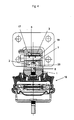
- Fig. 4 is a third embodiment of an assembly bearing 19 according to the invention shown with adapter according to the invention.
- the assembly bearing 19 differs from the assembly bearing 19 Fig. 3 in that the vertically arranged screw connection 20 has no vertically arranged internal thread which is connected to the screw 4 designed as the first fastening means 2 of the adapter, but a vertically arranged threaded bolt 25 which protrudes in the axial direction of the support bearing 21 in the direction of the adapter.
- the threaded bolt 25 penetrates the opening 6 of the adapter, wherein the adapter is connected by means of the second nut 26 and the threaded bolt 25 with the support bearing 21 of the unit bearing 19.
- the adapter itself is, with the exception of the first fastening device 2, according to the adapter Fig. 3 executed.
- the first nut 8 is rotatably disposed within the coupling part 1 by its polygonal profile, wherein the axes of the threaded bolt 25 and the second nut 26 are arranged perpendicular to each other.
- an adapter for a horizontal screw is attached to a core with depressed vertical screw. It must be created for the second nut 25 below the first nut 8 sufficient clearance around this mother, the tightening by a suitable key. The first nut 8 is adapted to this clearance and therefore made longer.
- the assembly bearings are formed by rubber-metal engine mount in the Fig. 1 and 2 without, in the Fig. 3 and 4 with hydraulic damping.
- the support bearings 21 of the respective assembly bearings each have a vertically arranged screw 20, wherein the assembly bearings 19 shown - are suitable and provided for mounting in a large series - each without the adapter.
- a specially designed engine, z. B. by other / additional ancillaries should, if possible, the same unit bearings are used, but this would often not be possible by the other / cramped Einbawerixie in the installation space without the use of the adapter.
- the assembly bearings shown are completed by the adapter.
- the support arms 9 shown can either be screwed to the engine, pushed over the coupling part 1 and then by means of the screw 5, which forms the second fastening means 3, or the support arm 9 is previously connected to the coupling part 1, and then the Motor bolted by the adapter that screws through the through holes 11, 12, 13, 14 are screwed.
- the coupling part 1 and the first nut 8 are made in the embodiments Fig. 1 to 4 each of metallic materials, as well as the support arm. 9
Landscapes
- Engineering & Computer Science (AREA)
- General Engineering & Computer Science (AREA)
- Mechanical Engineering (AREA)
- Connection Of Plates (AREA)
- Vibration Prevention Devices (AREA)
- Buildings Adapted To Withstand Abnormal External Influences (AREA)
- Pivots And Pivotal Connections (AREA)
Applications Claiming Priority (1)
| Application Number | Priority Date | Filing Date | Title |
|---|---|---|---|
| DE102011110490A DE102011110490A1 (de) | 2011-08-17 | 2011-08-17 | Adapter, dessen Verwendung und Aggregatelager mit Adapter |
Publications (3)
| Publication Number | Publication Date |
|---|---|
| EP2559910A2 true EP2559910A2 (fr) | 2013-02-20 |
| EP2559910A3 EP2559910A3 (fr) | 2015-04-01 |
| EP2559910B1 EP2559910B1 (fr) | 2018-11-14 |
Family
ID=46582511
Family Applications (1)
| Application Number | Title | Priority Date | Filing Date |
|---|---|---|---|
| EP12005189.1A Active EP2559910B1 (fr) | 2011-08-17 | 2012-07-13 | Adaptateur, son utilisation et palier d'agrégat avec adaptateur |
Country Status (3)
| Country | Link |
|---|---|
| EP (1) | EP2559910B1 (fr) |
| DE (1) | DE102011110490A1 (fr) |
| ES (1) | ES2706419T3 (fr) |
Family Cites Families (15)
| Publication number | Priority date | Publication date | Assignee | Title |
|---|---|---|---|---|
| DE1943618U (de) * | 1966-05-16 | 1966-08-04 | Baustahlgewebe Gmbh | Bauteilsatz zum aufbau eines zaunes, gelaenders od. dgl. |
| JPS57114032A (en) * | 1980-12-29 | 1982-07-15 | Hiroshi Teramachi | Torque transfer type bearing block |
| DE3437784A1 (de) * | 1984-10-16 | 1986-04-24 | Adam Opel AG, 6090 Rüsselsheim | Triebwerksaufhaengung |
| JP2760108B2 (ja) * | 1989-12-12 | 1998-05-28 | トヨタ自動車株式会社 | エンジン懸架装置 |
| DE4412879A1 (de) * | 1994-04-14 | 1995-10-19 | Freudenberg Carl Fa | Lageranordnung |
| DE29601355U1 (de) * | 1996-01-29 | 1997-06-05 | Frör, Werner, 91052 Erlangen | Verbindungsknoten für Baukonstruktionen |
| JP3613928B2 (ja) * | 1997-04-30 | 2005-01-26 | 日産自動車株式会社 | エンジンマウント装置 |
| DE19731128C2 (de) * | 1997-07-19 | 1999-09-23 | Volkswagen Ag | Pendelstütze für ein Aggregat in einem Kraftfahrzeug und elastisches Aggregatelager |
| US6105548A (en) * | 1998-11-03 | 2000-08-22 | Briggs & Stratton Corporation | Mounting apparatus for an engine and transmission |
| DE19915798C2 (de) * | 1999-02-24 | 2001-06-28 | Freudenberg Carl Fa | Schaltbares, hydraulisch dämpfendes Lager |
| KR20000060931A (ko) * | 1999-03-22 | 2000-10-16 | 정몽규 | 자동차의 파워 플랜트 마운트 |
| US6270051B1 (en) * | 1999-05-26 | 2001-08-07 | The Standard Products Company | Drive train mount adapter plate and pivot bracket |
| FR2809996B1 (fr) * | 2000-06-08 | 2002-10-11 | C F Gomma Barre Thomas | Support de suspension a debattement limite pour groupe motopropulseur et engin motorise muni d'un tel support |
| DE202005016961U1 (de) * | 2005-07-05 | 2006-11-16 | Eberhard, Michael | Bausatz |
| DE102008007137A1 (de) * | 2008-01-31 | 2009-08-06 | Carl Freudenberg Kg | Hydraulisch dämpfendes Aggregatelager |
-
2011
- 2011-08-17 DE DE102011110490A patent/DE102011110490A1/de not_active Ceased
-
2012
- 2012-07-13 ES ES12005189T patent/ES2706419T3/es active Active
- 2012-07-13 EP EP12005189.1A patent/EP2559910B1/fr active Active
Non-Patent Citations (1)
| Title |
|---|
| None |
Also Published As
| Publication number | Publication date |
|---|---|
| DE102011110490A1 (de) | 2013-02-21 |
| EP2559910A3 (fr) | 2015-04-01 |
| ES2706419T3 (es) | 2019-03-28 |
| EP2559910B1 (fr) | 2018-11-14 |
Similar Documents
| Publication | Publication Date | Title |
|---|---|---|
| DE102015016390B4 (de) | Aggregatelagerung für ein Fahrzeug-Antriebsaggregat | |
| EP0445591A1 (fr) | Dispositif d'accouplement pour une colonne de direction d'un véhicule automobile avec la queue de l'arbre d'un mécanisme de direction | |
| DE4302007C1 (de) | Einrichtung zum Verbinden eines Motorblocks mit einem Getriebeblock | |
| EP3063428A1 (fr) | Palier | |
| DE202007014325U1 (de) | Montageanordnung mit elastischem Ring | |
| DE102012011601A1 (de) | Verzwängungsfreies Befestigungssystem, insbesondere zur Befestigung von Lenkgetriebegehäusen | |
| DE20213362U1 (de) | Befestigungsanordnung für eine Heckleuchte | |
| DE69405925T2 (de) | Vorrichtung zur Kompensation eines Lagefehlers eines Antriebsystems auf einer Brennkraftmaschine | |
| DE102010024619B4 (de) | Vorgespanntes Differentialgetriebe ohne Zahnflankenwechsel | |
| DE102019206519B4 (de) | Aggregatelagerung in einem Fahrzeug | |
| EP0648928B1 (fr) | Machine à combustion interne avec un vilebrequin agencé par des chapeaux des paliers dans un bâtiment moteur | |
| EP2559910B1 (fr) | Adaptateur, son utilisation et palier d'agrégat avec adaptateur | |
| DE102005014217B4 (de) | Befestigungsvorrichtung für eine Dachreling | |
| DE102018109520A1 (de) | Vorrichtung | |
| DE102016112543B4 (de) | Rückenlehnentilger für Fahrzeugsitze, Fahrzeugsitz | |
| DE202018105205U1 (de) | Getriebe | |
| DE102012112362C5 (de) | Ventil mit einer Befestigungseinrichtung | |
| DE3442518A1 (de) | Elastisch nachgiebiges lenkergelenk, insbesondere fuer achslenker von nutzfahrzeugen | |
| DE102004044055A1 (de) | Toleranzausgleichsvorrichtung für zwei miteinander zu verschraubende Bauteile | |
| DE102011079617A1 (de) | Schraubverbindung | |
| DE102017214202A1 (de) | Dämpferlager und Verfahren zur Montage einer Kolbenstange mit Kabelabgang an einem solchen | |
| WO2002066848A1 (fr) | Entraineur a bride | |
| EP3190298B1 (fr) | Système de fixation amovible de composants | |
| DE8603445U1 (de) | Kopplungselement | |
| DE19724242C2 (de) | Mutter |
Legal Events
| Date | Code | Title | Description |
|---|---|---|---|
| PUAI | Public reference made under article 153(3) epc to a published international application that has entered the european phase |
Free format text: ORIGINAL CODE: 0009012 |
|
| AK | Designated contracting states |
Kind code of ref document: A2 Designated state(s): AL AT BE BG CH CY CZ DE DK EE ES FI FR GB GR HR HU IE IS IT LI LT LU LV MC MK MT NL NO PL PT RO RS SE SI SK SM TR |
|
| AX | Request for extension of the european patent |
Extension state: BA ME |
|
| PUAL | Search report despatched |
Free format text: ORIGINAL CODE: 0009013 |
|
| AK | Designated contracting states |
Kind code of ref document: A3 Designated state(s): AL AT BE BG CH CY CZ DE DK EE ES FI FR GB GR HR HU IE IS IT LI LT LU LV MC MK MT NL NO PL PT RO RS SE SI SK SM TR |
|
| AX | Request for extension of the european patent |
Extension state: BA ME |
|
| RIC1 | Information provided on ipc code assigned before grant |
Ipc: F16M 11/04 20060101ALI20150226BHEP Ipc: F16F 1/393 20060101ALI20150226BHEP Ipc: F16F 1/36 20060101AFI20150226BHEP |
|
| 17P | Request for examination filed |
Effective date: 20150528 |
|
| RBV | Designated contracting states (corrected) |
Designated state(s): AL AT BE BG CH CY CZ DE DK EE ES FI FR GB GR HR HU IE IS IT LI LT LU LV MC MK MT NL NO PL PT RO RS SE SI SK SM TR |
|
| RAP1 | Party data changed (applicant data changed or rights of an application transferred) |
Owner name: VIBRACOUSTIC GMBH |
|
| STAA | Information on the status of an ep patent application or granted ep patent |
Free format text: STATUS: EXAMINATION IS IN PROGRESS |
|
| 17Q | First examination report despatched |
Effective date: 20180202 |
|
| GRAP | Despatch of communication of intention to grant a patent |
Free format text: ORIGINAL CODE: EPIDOSNIGR1 |
|
| STAA | Information on the status of an ep patent application or granted ep patent |
Free format text: STATUS: GRANT OF PATENT IS INTENDED |
|
| INTG | Intention to grant announced |
Effective date: 20180726 |
|
| GRAS | Grant fee paid |
Free format text: ORIGINAL CODE: EPIDOSNIGR3 |
|
| GRAA | (expected) grant |
Free format text: ORIGINAL CODE: 0009210 |
|
| STAA | Information on the status of an ep patent application or granted ep patent |
Free format text: STATUS: THE PATENT HAS BEEN GRANTED |
|
| AK | Designated contracting states |
Kind code of ref document: B1 Designated state(s): AL AT BE BG CH CY CZ DE DK EE ES FI FR GB GR HR HU IE IS IT LI LT LU LV MC MK MT NL NO PL PT RO RS SE SI SK SM TR |
|
| REG | Reference to a national code |
Ref country code: GB Ref legal event code: FG4D Free format text: NOT ENGLISH |
|
| REG | Reference to a national code |
Ref country code: CH Ref legal event code: EP Ref country code: AT Ref legal event code: REF Ref document number: 1065204 Country of ref document: AT Kind code of ref document: T Effective date: 20181115 |
|
| REG | Reference to a national code |
Ref country code: DE Ref legal event code: R096 Ref document number: 502012013799 Country of ref document: DE |
|
| REG | Reference to a national code |
Ref country code: IE Ref legal event code: FG4D Free format text: LANGUAGE OF EP DOCUMENT: GERMAN |
|
| REG | Reference to a national code |
Ref country code: NL Ref legal event code: MP Effective date: 20181114 |
|
| REG | Reference to a national code |
Ref country code: LT Ref legal event code: MG4D |
|
| REG | Reference to a national code |
Ref country code: ES Ref legal event code: FG2A Ref document number: 2706419 Country of ref document: ES Kind code of ref document: T3 Effective date: 20190328 |
|
| PG25 | Lapsed in a contracting state [announced via postgrant information from national office to epo] |
Ref country code: IS Free format text: LAPSE BECAUSE OF FAILURE TO SUBMIT A TRANSLATION OF THE DESCRIPTION OR TO PAY THE FEE WITHIN THE PRESCRIBED TIME-LIMIT Effective date: 20190314 Ref country code: BG Free format text: LAPSE BECAUSE OF FAILURE TO SUBMIT A TRANSLATION OF THE DESCRIPTION OR TO PAY THE FEE WITHIN THE PRESCRIBED TIME-LIMIT Effective date: 20190214 Ref country code: HR Free format text: LAPSE BECAUSE OF FAILURE TO SUBMIT A TRANSLATION OF THE DESCRIPTION OR TO PAY THE FEE WITHIN THE PRESCRIBED TIME-LIMIT Effective date: 20181114 Ref country code: LT Free format text: LAPSE BECAUSE OF FAILURE TO SUBMIT A TRANSLATION OF THE DESCRIPTION OR TO PAY THE FEE WITHIN THE PRESCRIBED TIME-LIMIT Effective date: 20181114 Ref country code: NO Free format text: LAPSE BECAUSE OF FAILURE TO SUBMIT A TRANSLATION OF THE DESCRIPTION OR TO PAY THE FEE WITHIN THE PRESCRIBED TIME-LIMIT Effective date: 20190214 Ref country code: LV Free format text: LAPSE BECAUSE OF FAILURE TO SUBMIT A TRANSLATION OF THE DESCRIPTION OR TO PAY THE FEE WITHIN THE PRESCRIBED TIME-LIMIT Effective date: 20181114 Ref country code: FI Free format text: LAPSE BECAUSE OF FAILURE TO SUBMIT A TRANSLATION OF THE DESCRIPTION OR TO PAY THE FEE WITHIN THE PRESCRIBED TIME-LIMIT Effective date: 20181114 |
|
| PG25 | Lapsed in a contracting state [announced via postgrant information from national office to epo] |
Ref country code: SE Free format text: LAPSE BECAUSE OF FAILURE TO SUBMIT A TRANSLATION OF THE DESCRIPTION OR TO PAY THE FEE WITHIN THE PRESCRIBED TIME-LIMIT Effective date: 20181114 Ref country code: AL Free format text: LAPSE BECAUSE OF FAILURE TO SUBMIT A TRANSLATION OF THE DESCRIPTION OR TO PAY THE FEE WITHIN THE PRESCRIBED TIME-LIMIT Effective date: 20181114 Ref country code: PT Free format text: LAPSE BECAUSE OF FAILURE TO SUBMIT A TRANSLATION OF THE DESCRIPTION OR TO PAY THE FEE WITHIN THE PRESCRIBED TIME-LIMIT Effective date: 20190314 Ref country code: RS Free format text: LAPSE BECAUSE OF FAILURE TO SUBMIT A TRANSLATION OF THE DESCRIPTION OR TO PAY THE FEE WITHIN THE PRESCRIBED TIME-LIMIT Effective date: 20181114 Ref country code: GR Free format text: LAPSE BECAUSE OF FAILURE TO SUBMIT A TRANSLATION OF THE DESCRIPTION OR TO PAY THE FEE WITHIN THE PRESCRIBED TIME-LIMIT Effective date: 20190215 Ref country code: NL Free format text: LAPSE BECAUSE OF FAILURE TO SUBMIT A TRANSLATION OF THE DESCRIPTION OR TO PAY THE FEE WITHIN THE PRESCRIBED TIME-LIMIT Effective date: 20181114 |
|
| PG25 | Lapsed in a contracting state [announced via postgrant information from national office to epo] |
Ref country code: CZ Free format text: LAPSE BECAUSE OF FAILURE TO SUBMIT A TRANSLATION OF THE DESCRIPTION OR TO PAY THE FEE WITHIN THE PRESCRIBED TIME-LIMIT Effective date: 20181114 Ref country code: DK Free format text: LAPSE BECAUSE OF FAILURE TO SUBMIT A TRANSLATION OF THE DESCRIPTION OR TO PAY THE FEE WITHIN THE PRESCRIBED TIME-LIMIT Effective date: 20181114 Ref country code: IT Free format text: LAPSE BECAUSE OF FAILURE TO SUBMIT A TRANSLATION OF THE DESCRIPTION OR TO PAY THE FEE WITHIN THE PRESCRIBED TIME-LIMIT Effective date: 20181114 Ref country code: PL Free format text: LAPSE BECAUSE OF FAILURE TO SUBMIT A TRANSLATION OF THE DESCRIPTION OR TO PAY THE FEE WITHIN THE PRESCRIBED TIME-LIMIT Effective date: 20181114 |
|
| REG | Reference to a national code |
Ref country code: DE Ref legal event code: R097 Ref document number: 502012013799 Country of ref document: DE |
|
| PG25 | Lapsed in a contracting state [announced via postgrant information from national office to epo] |
Ref country code: SM Free format text: LAPSE BECAUSE OF FAILURE TO SUBMIT A TRANSLATION OF THE DESCRIPTION OR TO PAY THE FEE WITHIN THE PRESCRIBED TIME-LIMIT Effective date: 20181114 Ref country code: SK Free format text: LAPSE BECAUSE OF FAILURE TO SUBMIT A TRANSLATION OF THE DESCRIPTION OR TO PAY THE FEE WITHIN THE PRESCRIBED TIME-LIMIT Effective date: 20181114 Ref country code: RO Free format text: LAPSE BECAUSE OF FAILURE TO SUBMIT A TRANSLATION OF THE DESCRIPTION OR TO PAY THE FEE WITHIN THE PRESCRIBED TIME-LIMIT Effective date: 20181114 Ref country code: EE Free format text: LAPSE BECAUSE OF FAILURE TO SUBMIT A TRANSLATION OF THE DESCRIPTION OR TO PAY THE FEE WITHIN THE PRESCRIBED TIME-LIMIT Effective date: 20181114 |
|
| PLBE | No opposition filed within time limit |
Free format text: ORIGINAL CODE: 0009261 |
|
| STAA | Information on the status of an ep patent application or granted ep patent |
Free format text: STATUS: NO OPPOSITION FILED WITHIN TIME LIMIT |
|
| 26N | No opposition filed |
Effective date: 20190815 |
|
| PG25 | Lapsed in a contracting state [announced via postgrant information from national office to epo] |
Ref country code: SI Free format text: LAPSE BECAUSE OF FAILURE TO SUBMIT A TRANSLATION OF THE DESCRIPTION OR TO PAY THE FEE WITHIN THE PRESCRIBED TIME-LIMIT Effective date: 20181114 |
|
| PG25 | Lapsed in a contracting state [announced via postgrant information from national office to epo] |
Ref country code: MC Free format text: LAPSE BECAUSE OF FAILURE TO SUBMIT A TRANSLATION OF THE DESCRIPTION OR TO PAY THE FEE WITHIN THE PRESCRIBED TIME-LIMIT Effective date: 20181114 |
|
| REG | Reference to a national code |
Ref country code: CH Ref legal event code: PL |
|
| PG25 | Lapsed in a contracting state [announced via postgrant information from national office to epo] |
Ref country code: TR Free format text: LAPSE BECAUSE OF FAILURE TO SUBMIT A TRANSLATION OF THE DESCRIPTION OR TO PAY THE FEE WITHIN THE PRESCRIBED TIME-LIMIT Effective date: 20181114 |
|
| REG | Reference to a national code |
Ref country code: DE Ref legal event code: R082 Ref document number: 502012013799 Country of ref document: DE Representative=s name: PATENTANWAELTE OLBRICHT, BUCHHOLD, KEULERTZ PA, DE Ref country code: BE Ref legal event code: MM Effective date: 20190731 |
|
| PG25 | Lapsed in a contracting state [announced via postgrant information from national office to epo] |
Ref country code: BE Free format text: LAPSE BECAUSE OF NON-PAYMENT OF DUE FEES Effective date: 20190731 Ref country code: LU Free format text: LAPSE BECAUSE OF NON-PAYMENT OF DUE FEES Effective date: 20190713 Ref country code: LI Free format text: LAPSE BECAUSE OF NON-PAYMENT OF DUE FEES Effective date: 20190731 Ref country code: CH Free format text: LAPSE BECAUSE OF NON-PAYMENT OF DUE FEES Effective date: 20190731 |
|
| PG25 | Lapsed in a contracting state [announced via postgrant information from national office to epo] |
Ref country code: IE Free format text: LAPSE BECAUSE OF NON-PAYMENT OF DUE FEES Effective date: 20190713 |
|
| REG | Reference to a national code |
Ref country code: AT Ref legal event code: MM01 Ref document number: 1065204 Country of ref document: AT Kind code of ref document: T Effective date: 20190713 |
|
| PG25 | Lapsed in a contracting state [announced via postgrant information from national office to epo] |
Ref country code: AT Free format text: LAPSE BECAUSE OF NON-PAYMENT OF DUE FEES Effective date: 20190713 |
|
| PG25 | Lapsed in a contracting state [announced via postgrant information from national office to epo] |
Ref country code: CY Free format text: LAPSE BECAUSE OF FAILURE TO SUBMIT A TRANSLATION OF THE DESCRIPTION OR TO PAY THE FEE WITHIN THE PRESCRIBED TIME-LIMIT Effective date: 20181114 |
|
| PG25 | Lapsed in a contracting state [announced via postgrant information from national office to epo] |
Ref country code: MT Free format text: LAPSE BECAUSE OF FAILURE TO SUBMIT A TRANSLATION OF THE DESCRIPTION OR TO PAY THE FEE WITHIN THE PRESCRIBED TIME-LIMIT Effective date: 20181114 Ref country code: HU Free format text: LAPSE BECAUSE OF FAILURE TO SUBMIT A TRANSLATION OF THE DESCRIPTION OR TO PAY THE FEE WITHIN THE PRESCRIBED TIME-LIMIT; INVALID AB INITIO Effective date: 20120713 |
|
| REG | Reference to a national code |
Ref country code: DE Ref legal event code: R081 Ref document number: 502012013799 Country of ref document: DE Owner name: VIBRACOUSTIC SE, DE Free format text: FORMER OWNER: VIBRACOUSTIC GMBH, 64293 DARMSTADT, DE |
|
| REG | Reference to a national code |
Ref country code: ES Ref legal event code: PC2A Owner name: VIBRACOUSTIC SE Effective date: 20210823 |
|
| PGFP | Annual fee paid to national office [announced via postgrant information from national office to epo] |
Ref country code: ES Payment date: 20210927 Year of fee payment: 10 |
|
| PG25 | Lapsed in a contracting state [announced via postgrant information from national office to epo] |
Ref country code: MK Free format text: LAPSE BECAUSE OF FAILURE TO SUBMIT A TRANSLATION OF THE DESCRIPTION OR TO PAY THE FEE WITHIN THE PRESCRIBED TIME-LIMIT Effective date: 20181114 |
|
| PGFP | Annual fee paid to national office [announced via postgrant information from national office to epo] |
Ref country code: GB Payment date: 20220721 Year of fee payment: 11 |
|
| PGFP | Annual fee paid to national office [announced via postgrant information from national office to epo] |
Ref country code: FR Payment date: 20220720 Year of fee payment: 11 |
|
| REG | Reference to a national code |
Ref country code: ES Ref legal event code: FD2A Effective date: 20230901 |
|
| PG25 | Lapsed in a contracting state [announced via postgrant information from national office to epo] |
Ref country code: ES Free format text: LAPSE BECAUSE OF NON-PAYMENT OF DUE FEES Effective date: 20220714 |
|
| GBPC | Gb: european patent ceased through non-payment of renewal fee |
Effective date: 20230713 |
|
| PG25 | Lapsed in a contracting state [announced via postgrant information from national office to epo] |
Ref country code: GB Free format text: LAPSE BECAUSE OF NON-PAYMENT OF DUE FEES Effective date: 20230713 |
|
| PG25 | Lapsed in a contracting state [announced via postgrant information from national office to epo] |
Ref country code: FR Free format text: LAPSE BECAUSE OF NON-PAYMENT OF DUE FEES Effective date: 20230731 |
|
| PGFP | Annual fee paid to national office [announced via postgrant information from national office to epo] |
Ref country code: DE Payment date: 20250731 Year of fee payment: 14 |