EP2559929A1 - Traversée de conduite avec volume de contrôle - Google Patents
Traversée de conduite avec volume de contrôle Download PDFInfo
- Publication number
- EP2559929A1 EP2559929A1 EP11006718A EP11006718A EP2559929A1 EP 2559929 A1 EP2559929 A1 EP 2559929A1 EP 11006718 A EP11006718 A EP 11006718A EP 11006718 A EP11006718 A EP 11006718A EP 2559929 A1 EP2559929 A1 EP 2559929A1
- Authority
- EP
- European Patent Office
- Prior art keywords
- line
- elastomeric body
- test volume
- conduit
- wall
- Prior art date
- Legal status (The legal status is an assumption and is not a legal conclusion. Google has not performed a legal analysis and makes no representation as to the accuracy of the status listed.)
- Granted
Links
Images


Classifications
-
- F—MECHANICAL ENGINEERING; LIGHTING; HEATING; WEAPONS; BLASTING
- F16—ENGINEERING ELEMENTS AND UNITS; GENERAL MEASURES FOR PRODUCING AND MAINTAINING EFFECTIVE FUNCTIONING OF MACHINES OR INSTALLATIONS; THERMAL INSULATION IN GENERAL
- F16L—PIPES; JOINTS OR FITTINGS FOR PIPES; SUPPORTS FOR PIPES, CABLES OR PROTECTIVE TUBING; MEANS FOR THERMAL INSULATION IN GENERAL
- F16L5/00—Devices for use where pipes, cables or protective tubing pass through walls or partitions
- F16L5/02—Sealing
- F16L5/08—Sealing by means of axial screws compressing a ring or sleeve
-
- F—MECHANICAL ENGINEERING; LIGHTING; HEATING; WEAPONS; BLASTING
- F16—ENGINEERING ELEMENTS AND UNITS; GENERAL MEASURES FOR PRODUCING AND MAINTAINING EFFECTIVE FUNCTIONING OF MACHINES OR INSTALLATIONS; THERMAL INSULATION IN GENERAL
- F16L—PIPES; JOINTS OR FITTINGS FOR PIPES; SUPPORTS FOR PIPES, CABLES OR PROTECTIVE TUBING; MEANS FOR THERMAL INSULATION IN GENERAL
- F16L5/00—Devices for use where pipes, cables or protective tubing pass through walls or partitions
- F16L5/02—Sealing
- F16L5/14—Sealing for double-walled or multi-channel pipes
-
- H—ELECTRICITY
- H02—GENERATION; CONVERSION OR DISTRIBUTION OF ELECTRIC POWER
- H02G—INSTALLATION OF ELECTRIC CABLES OR LINES, OR OF COMBINED OPTICAL AND ELECTRIC CABLES OR LINES
- H02G3/00—Installations of electric cables or lines or protective tubing therefor in or on buildings, equivalent structures or vehicles
- H02G3/22—Installations of cables or lines through walls, floors or ceilings, e.g. into buildings
Definitions
- the present invention relates to a conduit bushing for sealingly passing a conduit through a wall with an elastomeric body and a tensioning device for tensioning the elastomeric body.
- Cable bushings are known from the prior art, in which an elastomeric body between two clamping plates in the direction of the line (line direction) is compressed and as a result expands perpendicular to the line direction and sealingly applies both to the line and the wall, ie to a Reveal of the wall opening.
- this is only one of several ways of assembling the elastomer body, which illustrate the field of application, but is not intended to limit the present invention in its generality.
- the present invention has for its object to provide a cable bushing with improved application security, which can be produced in an economically advantageous manner.
- this object solves a cable bushing with an elastomeric body and a clamping device for bracing the elastomer body, so that it applies sealingly due to the tensioning of the line, as well as with a spacer, which is designed to limit the tensioned elastomer body a test volume In its interior , which is pressurizable via a valve body.
- the test volume is in any case based on the line direction within the elastomer body and may also extend to the outside with respect to a distance to the center axis of the line and hereinafter referred to as the direction of distance direction, so bordering on a distance direction in the outer sealing surface of the elastomer body and so for example be provided for a leak test of this outer sealing surface.
- the direction of distance direction so bordering on a distance direction in the outer sealing surface of the elastomer body and so for example be provided for a leak test of this outer sealing surface.
- the test volume is advantageously arranged in the interior of the elastomer body in a cable bushing according to the invention, this is thus an integral part of the mounted cable bushing.
- the inventor has found that providing, thus sealing, such a test volume can entail considerable expense - in the case of the aforementioned cellar space, this would either have to be sealed and pressurized or It would temporarily be used a second line implementation, which is labor-intensive and can be problematic in terms of space requirements.
- the integrated according to the invention in the elastomer body test volume has the advantage that a leak test, for example, not only after the assembly can be made, but also in the subsequent is possible, for example in the context of regular maintenance.
- test volume arranged in the interior of the elastomer body could also be realized without an adjacent spacer according to the invention, for example by milling the test volume.
- the inventor has found that this can be time consuming and thus disadvantageous in terms of economical manufacture of the lead bushing.
- a spacer which holds the test volume free in the braced elastomer body is provided, which adjoins the elastomer body.
- the elastomeric body is divided into two parts and then the two elastomer body parts are spaced apart by the spacer in the direction of the line.
- the spacer may be, for example, firmly connected to one or both elastomer body parts, such as by a joint connection, in particular an adhesive bond, or even rest against the elastomer body parts.
- a corresponding test volume that can be produced by bringing the elastomeric body and the spacer into contact with each other is advantageous over a milled-in test volume, because correspondingly complicated milling steps, which are disadvantageous in particular in a mass production, are eliminated.
- a line feedthrough according to the invention can be produced by dividing an elastomeric body into a dividing surface oriented obliquely to the direction of conduction (preferably perpendicular thereto) (or by producing two corresponding tell) and then providing a spacer between the elastomeric body parts.
- the subject matter of the present invention is not limited thereto, so that the spacer could for example also be integrally formed with an elastomeric body part and would accordingly only adjoin the other elastomeric body part.
- elastomeric body "bordering" means so at this fitting, but not in the contact surface integrally formed with it - in the whole could be an elastomeric body according to the invention certainly integrally formed, such as in the case of an injection molded or generally produced in a molding process elastomer body whose Test volume between themselves enclosing elastomer body parts are connected by an example provided for injecting the elastomeric material channel with each other.
- the spacer In this example, it could be molded onto an elastomeric body region and after assembly, ie after a corresponding bending of the one-piece elastomeric body from the beginning, rest against the other elastomeric body region.
- the tight contact with a then passed line is achieved by the bracing of the elastomer body with the clamping device, wherein an actuation of the clamping device deformed relative to the line direction on both sides of the fürvolumens arranged areas of the elastomer body, so on both sides of the scholarvolumens a sealing contact of the elastomeric body to the line causes.
- the clamping device thus deforms both elastomer body parts.
- a tensioning device compressing the elastomer body in the spacing direction may be provided, or else a tensioning device which compresses the elastomeric body in the direction of the line and thus causes its expansion in the direction of spacing.
- the elastomer body for example, can also be clamped together with other elastomer bodies by a common clamping device.
- Such elastomeric bodies could have a rectangular outer shape as seen in the conduit direction, wherein the side surfaces of the plurality of elastomeric body could then abut each other or on the reveal of a wall opening.
- valve body for example, also distributed independently of the cable feedthrough and then only on their installation or be used.
- one is preferably provided as part of the cable feedthrough Valve body, such as in the context of the dependent claims even further explained, attachable to a clamping plate valve body.
- the elastomeric body is designed to be applied as a result of the bracing of a soffit of the wall opening so that the soffit of the wall opening limits the test volume.
- "Reveal” generally means a through opening in the spacing direction limiting, preferably circumferential surface and may for example also be formed by an inserted into the wall opening, screwed about with the wall, frame.
- the reveal corresponds to the inner circumferential surface of an inserted into the wall, for example, cast-in, casing or the wall of an introduced into the wall core hole.
- a region of the soffit then limits the sealing volume, preferably circumferentially, so that the test volume adjoins two sealing surfaces of the elastomeric body that are spaced apart from one another in the direction of the line and form a soffit. Accordingly, by pressurizing the test volume, the sealing contact of the elastomer body on the reveal of the wall opening, ie the correct formation of the outside in the distance direction on the elastomer body arranged, preferably circumferential sealing surfaces are checked.
- the soffit of the wall opening limits the test volume together with the line, so that advantageously by pressurizing a single, continuous test volume, the sealing contact of the elastomeric body can be checked on both the line and the soffit.
- the elastomeric body is constructed with respect to the conduit direction from at least two elastomeric body parts which are integral therewith and these are designed to define at least a region of the body between them To include the test volume.
- exactly two integral elastomer body parts are provided with respect to the line direction, ie it does not connect to an elastomer body part delimiting the test volume at the side opposite the test volume. The line feedthrough can thus be made compact in spite of the test volume provided inside with respect to the line direction.
- the one-piece structure of the elastomer body parts initially relates to the line direction, ie, for example, the same line contacting segments of an elastomer body part may well be separated from each other by parallel to the line direction separation surfaces;
- an elastomer body part is integrally formed as a whole, that is possibly also in spite of a parallel to the conduit direction separating surface in itself contiguous.
- a different material is provided than for the elastomeric body, for example a hard plastic material or a metallic material, such as an alloy.
- a different material is provided than for the elastomeric body, for example a hard plastic material or a metallic material, such as an alloy.
- a minimum width in the line direction is thus predetermined for the test volume, so that even in the case of a more strongly strained elastomer body, a test volume adjacent to the sealing surfaces to be tested is kept free.
- the spacer is designed as a transverse to the conduit direction, preferably perpendicular thereto, extending intermediate plate with a line taking into account passage opening.
- the intermediate plate may be designed substantially substantially a clamping plate, which helps reduce the number of different components and thus reduce the manufacturing cost can.
- Plate here means a body whose extension in the distance direction is greater than that in the direction of conduction.
- a parting line is provided which connects a region of the test volume bounded by the line under pressure fluid to a region thereof delimited by the reveal of the wall opening. More preferably, such a parting line is provided in the intermediate plate in conjunction with an elastomeric body in which a directionally oriented, preferably parallel, separating surface extends away from the conduit outwardly to an outer surface of the elastomeric body. A corresponding elastomeric body is then hinged to a direction oriented in the direction of the pivot axis, so it can be set to an already laid line.
- Corresponding joints can in the case of an elastomeric body provided for a plurality of lines at the same time (but also independent of the above-described Aufklapples) connect the areas of the test volume arranged around the respective lines, so that this can be pressurized in the ideal case with only one valve body.
- the spacer has a sleeve which is set on a clamping bolt passing through the elastomer body, which cooperates with a clamping plate for the purpose of bracing.
- the sleeve is preferably designed as an elongated body, that is to say has a length taken in the direction of the conduit which corresponds at least to its outer diameter (in the case of a non-circular cross-section to the mean of the smallest and largest dimensions), particularly preferably at least twice this.
- the sleeve is preferably designed as a tubular body, wherein for transmitting force to the elastomeric body ideally a contact surface is provided which is larger than the surface of the sleeve (usually an annular surface) in a direction perpendicular to the direction of line, based on the direction of line center cutting plane.
- the sleeve can thus be widened, for example, the end, so bear with a flange on the elastomer body.
- the sleeve to increase the contact surface adjacent to a contact plate, so that the combination of sleeve and contact plate keeps the test volume.
- the sleeve can also be attached to the clamping plate, so for example, inserted with a tapered end portion or screwed.
- FIG. 1 Another embodiment, which is also considered to be independent of the features of the main claim (but optionally in connection with other features of the overall disclosure) as an invention and is intended to be disclosed in this form, relates to a combination of clamping plate and valve body, wherein the valve body attachable to the clamping plate is and can be applied together with the clamping plate to the elastomer body.
- the clamping plate is adapted to compress the elastomeric body in the conduit direction, such as in the manner described above cooperating with another clamping plate and clamping bolt so that the elastomeric body due to the compression expands perpendicular to the conduit direction and sealingly against the line and preferably a soffit of the wall opening applies.
- an external thread can be provided on the valve body that can be fastened to the clamping plate, which can be screwed into a corresponding thread provided in a passage opening in the clamping plate.
- the valve body can also be attached solely by a plug connection to the clamping plate and, for example, locked or secured with a snap ring; one of the then adjacent to the elastomeric body side inserted valve body may for example also be secured alone with a flange on the clamping plate then by the pressure of the elastomeric body.
- this embodiment can offer, for example, the advantage that the line feedthrough can be distributed equally with the valve body as an integral part thereof. Since a stiff material is typically provided for the clamping plate, such as a metallic material, a valve body, also rigid and typically also made of a metallic material, may also be well secured thereto or securely held in position.
- clamping plate and valve body can be applied together to the elastomeric body
- the subject invention should also be realized when first the clamping plate attached to the elastomeric body and then the valve body is attached to the clamping plate; It is crucial that the valve body is in any case not exclusively attached to the clamping plate on the elastomeric body, but valve body and clamping plate are attached to each other fitting.
- a fastened to the clamping plate or attachable valve body need not necessarily what could otherwise be provided for mounting purposes, in the direction of conduct into the elastomeric body extend into, but can be made compact based on the line direction. Therefore, a valve body which extends in the elastomer body over at most 50%, in this order increasingly preferably at most 40%, 30%, 20%, 10%, of the distance between the clamping plate and the test volume is preferred; Particularly preferably, the valve body does not extend into the elastomeric body, but at most is attached to it.
- the invention also relates to a method for producing a cable bushing, wherein an elastomeric body provided and a spacer is attached to this; the attachment of the spacer can be done before, after or simultaneously with the preparation of the clamping device.
- spacers and elastomeric bodies adjoin one another at the time of manufacture, but can subsequently also be joined to form a one-piece body, for example by a first, elastomeric body spacer spacers still adjacent to the elastomeric body are formed integrally with the elastomeric body by vulcanizing the interface.
- the invention is also directed to the use of a corresponding cable bushing for sealing a power, gas, water, heat, telecommunications, signal or data line in a building wall, ship wall or housing wall.
- the installation of the cable bushing, so the insertion and bracing, preferably from only one side of the wall and the pressurization is carried out from the same side of the wall.
- the other side of the wall must therefore advantageously not necessarily be accessible, but can remain covered with soil, for example.
- the cable feedthrough can be placed on the conduit, for example, on one side of the wall and pushed into the through opening from the same Rare wall, clamped and tested for leaks by pressurization.
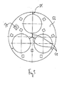
- the elastomeric body 4 expands due to the compression in the direction of line 2 perpendicular to it, ie in the direction of spacing 8, and places so tightly against a soffit 9 of the opening in the wall 3 and a line 10 at.
- the line 10 is a multipolar cable in this case.
- the elastomeric body 4 is designed in two parts, wherein the two integral elastomer body parts 4a, b are spaced apart by an intermediate plate 11.
- the intermediate plate 11 does not extend as far as the reveal 9 of the wall opening, as far as the line 10, so that between the elastomer body parts 4a, b a test volume 12 limited by a reveal 9 and a line 10 is kept free.
- the intermediate plate 11 is provided as well as clamping plates 5 and clamping bolt 6 made of metal and spaced from the elastomer body parts 4a, b adjacent to each other.
- the test volume 12 thus borders, on the one hand, on an outside circumferential Dirht character 13 of the elastomeric body 4 to the soffit 9 of the wall opening and on the other hand to a sealing surface 14 of the elastomer body to the line 10 Belde Dichtftumbleen 13, 14 are divided into two parts relative to the line direction 2, that is interrupted by the test volume 12.
- the test volume 12 is adjacent both to the annulus 9 and to the line 10 at each of two sealing surfaces 13a, b and 14a, b, which are each formed by an elastomeric body part 4a, b.
- the test volume 12 is thus arranged with respect to the conduit direction 2 within the elastomer body 4.
- the test volume 12 can be pressurized via a valve body 15 seated in the clamping plate 5b, so that the sealing surfaces 13a, b and 14a, b can be checked for leaks.
- the valve body 15 may be in the simplest case, a screwed into the clamping plate 5b car valve and the leak test then be made with an air pump with pressure gauge.
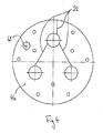
- the cable bushing 1 is in FIG. 2 in the direction of line 2 looking in a plan view.
- two more lines 10b, c can be seen.
- the clamping plate 5b is designed divided by joints 21, so can together with the divided by joints 22 elastomeric body 4 (see FIGS. 4 and 6 ) and so also be placed on already laid lines 10a, b, c.
- the parting lines 21 correspond to the separating surfaces 22, in that each one clamping plate part with a by the separating surface or surfaces 22 from the remaining elastomeric body part 4a, b separated, but still with the remaining elastomeric body part 4a, b related area of the elastomer body part 4a, b moves can be. In the assembled state, however, the parting lines 21 do not coincide with the separating surfaces 22, but the separating surfaces 22 are as far as possible covered by a continuous chipboard part.
- FIGS. 3 to 7 show individual components of the line bushing 1 according to the FIGS. 1 and 2 , based on FIG. 1 in a sequence from left to right, that is accordingly in FIG. 3 starting with the clamping plate 5b.
- a further passage opening 31 is provided, in which the valve body 15 is retracted in a manner known for passenger car valves manner.
- FIG. 4 shows a first, with assembled cable entry 1 then adjacent to the clamping plate 5b elastomeric body part 4b.
- a further through-opening 41 can be seen, which then connects the test volume 12 to the valve body 31 under pressure-fluid pressure.
- the test volume 12 is determined by the in FIG. 5 shown, provided between the elastomeric body parts 4a, b intermediate plate 11 is provided.
- the intermediate plate 11 is analogous to the clamping plates 5a, b divided by parting lines 51 in intermediate plate. Furthermore, through openings for the lines 10a, b, c and the clamping bolts 6 are likewise provided.
- a passage opening 52 is additionally introduced, specifically where the passage opening 41 provided in the elastomer body part 4b opens.
- the passage opening 52 is in the assembled line bushing 1, that is, at both sides of the intermediate plate 11 adjacent elastomer body parts 4a, b, then connected via a gap 53 druckfludisch with an arranged at the line 10b annular region of the test volume.
- This annular region is furthermore connected via the parting lines 51 to annular regions of the test volume 12 arranged around the lines 10 a, c.
- these three arranged at the lines 10a, b, c areas with a likewise annular, but limited by the reveal 9 of the wall opening, ie outside circulating region of the test volume 12 pressure fluidly connected, and also via the joints 51.
- the joints 51 serve on the one hand the Aufklappiere the line bushing 1 and on the other hand advantageously connect different areas of the test volume 12 pressure fluidly with each other, so that the individual areas can be pressurized via only a single valve body 15.
- elastomer body part 4a corresponds to the elastomer body part 4b, apart from the non-existent through hole 41.
- FIG. 7 Illustrated clamping plate 5a of the not introduced here Through opening 31 apart from those FIG. 3 ,
- the clamping plates 5a, b and also the intermediate plate 11 are thus largely constructed analogously to small adjustments, which is advantageous in manufacturing view.
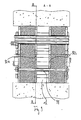
- FIG. 9 shows a line bushing 1, in which the test volume 12 is increased by set on the clamping bolt 6 sleeves 91; the bearing plates 92 correspond to a countersink for receiving a complementary, opposite the other sleeve thin-walled end-side sleeve portion apart from the clamping plates 5a, b or the intermediate plate 11.
- Ferner is in the spacer plate 92 a the valve body 15 pressure fluidly connected to the test volume 12 through hole provided, which the basis of FIG. 4 explained passage opening 41 in the elastomeric body part 4b extended.
- the abutment plate 92 a of the basis of FIG. 5 explained intermediate plate 11 are made starting, which also in FIG. 10 shown section through the spacer plate 92 a with perpendicular to the direction of line 2 lying sectional plane illustrated.
- the spacer plate 92b can be produced starting from a clamping plate 5a, b, for which purpose the passage openings provided for the clamping bolts 6 for receiving the sleeves 91 are to be raised. It can therefore be advantageously realized by some basic bodies by possibly minor adjustments a plurality of different cable bushings 1, such as cable bushings 1 with only formed by an intermediate plate 11 test volumes 12 as well as cable bushings 1, the test volumes 12 are enlarged by sleeves 91.
Landscapes
- Engineering & Computer Science (AREA)
- General Engineering & Computer Science (AREA)
- Architecture (AREA)
- Civil Engineering (AREA)
- Structural Engineering (AREA)
- Mechanical Engineering (AREA)
- Installation Of Indoor Wiring (AREA)
Priority Applications (2)
| Application Number | Priority Date | Filing Date | Title |
|---|---|---|---|
| EP11006718.8A EP2559929B1 (fr) | 2011-08-17 | 2011-08-17 | Traversée de conduite avec volume de contrôle |
| PL11006718T PL2559929T3 (pl) | 2011-08-17 | 2011-08-17 | Przepust przewodowy z objętością kontrolną |
Applications Claiming Priority (1)
| Application Number | Priority Date | Filing Date | Title |
|---|---|---|---|
| EP11006718.8A EP2559929B1 (fr) | 2011-08-17 | 2011-08-17 | Traversée de conduite avec volume de contrôle |
Publications (2)
| Publication Number | Publication Date |
|---|---|
| EP2559929A1 true EP2559929A1 (fr) | 2013-02-20 |
| EP2559929B1 EP2559929B1 (fr) | 2014-05-28 |
Family
ID=44587609
Family Applications (1)
| Application Number | Title | Priority Date | Filing Date |
|---|---|---|---|
| EP11006718.8A Active EP2559929B1 (fr) | 2011-08-17 | 2011-08-17 | Traversée de conduite avec volume de contrôle |
Country Status (2)
| Country | Link |
|---|---|
| EP (1) | EP2559929B1 (fr) |
| PL (1) | PL2559929T3 (fr) |
Cited By (2)
| Publication number | Priority date | Publication date | Assignee | Title |
|---|---|---|---|---|
| SE2251185A1 (en) * | 2022-10-10 | 2024-04-11 | Roxtec Ab | A transit system and method for retaining cables |
| WO2025133236A1 (fr) * | 2023-12-20 | 2025-06-26 | Hauff-Technik Gmbh & Co. Kg | Dispositif d'obturation pour un élément de paroi ou de plancher |
Citations (4)
| Publication number | Priority date | Publication date | Assignee | Title |
|---|---|---|---|---|
| US5235138A (en) * | 1991-06-24 | 1993-08-10 | Shah Jagdish H | Penetration plug for pressure vessels |
| DE10150075A1 (de) * | 2001-10-10 | 2003-04-17 | Roxtec Ingenieur Gmbh | Modulare Schottung zur dichten Durchführung von Kabeln und Rohrleitungen durch Bauteile aller Art (mit nachweisbarer Dichte) |
| WO2005059421A1 (fr) * | 2003-12-17 | 2005-06-30 | Structural Science Limited | Joint de tuyau |
| EP1843071A1 (fr) * | 2006-04-03 | 2007-10-10 | Hauff-Technik GmbH & Co. KG | Bourrage d'étanchéité pour l'utilisation dans un mur |
-
2011
- 2011-08-17 PL PL11006718T patent/PL2559929T3/pl unknown
- 2011-08-17 EP EP11006718.8A patent/EP2559929B1/fr active Active
Patent Citations (4)
| Publication number | Priority date | Publication date | Assignee | Title |
|---|---|---|---|---|
| US5235138A (en) * | 1991-06-24 | 1993-08-10 | Shah Jagdish H | Penetration plug for pressure vessels |
| DE10150075A1 (de) * | 2001-10-10 | 2003-04-17 | Roxtec Ingenieur Gmbh | Modulare Schottung zur dichten Durchführung von Kabeln und Rohrleitungen durch Bauteile aller Art (mit nachweisbarer Dichte) |
| WO2005059421A1 (fr) * | 2003-12-17 | 2005-06-30 | Structural Science Limited | Joint de tuyau |
| EP1843071A1 (fr) * | 2006-04-03 | 2007-10-10 | Hauff-Technik GmbH & Co. KG | Bourrage d'étanchéité pour l'utilisation dans un mur |
Cited By (3)
| Publication number | Priority date | Publication date | Assignee | Title |
|---|---|---|---|---|
| SE2251185A1 (en) * | 2022-10-10 | 2024-04-11 | Roxtec Ab | A transit system and method for retaining cables |
| SE546136C2 (en) * | 2022-10-10 | 2024-06-04 | Roxtec Ab | A transit system and method for retaining cables |
| WO2025133236A1 (fr) * | 2023-12-20 | 2025-06-26 | Hauff-Technik Gmbh & Co. Kg | Dispositif d'obturation pour un élément de paroi ou de plancher |
Also Published As
| Publication number | Publication date |
|---|---|
| PL2559929T3 (pl) | 2014-11-28 |
| EP2559929B1 (fr) | 2014-05-28 |
Similar Documents
| Publication | Publication Date | Title |
|---|---|---|
| EP3008370B1 (fr) | Collier de serrage ou d'attache | |
| DE102016114577A1 (de) | Vorrichtung und Verfahren zur Kabeldurchführung durch einen Wanddurchbruch | |
| DE112008003080B4 (de) | Schlauchleitungsverbinder sowie Leitungssatz | |
| DE102007042589A1 (de) | Einrichtung zur kraftstoffdichten Durchführung von elektrischen Kontaktelementen durch eine Wandung, sowie derartiges Kontaktelement | |
| DE102017212009A1 (de) | Zugentlastungstülle | |
| DE102004044917A1 (de) | Lösbare Steckverbindung für Rohrleitungen od. dgl. | |
| EP2648294B1 (fr) | Dispositif d'étanchéification ultérieure d'un boîtier d'isolation rempli de gaz isolant dans la technologie haute tension | |
| EP3329500B1 (fr) | Dispositif antidéflagrant pour traversée de boulon et son procédé de fabrication | |
| DE3838935A1 (de) | Kupplungsstueck | |
| DE60037237T2 (de) | Verbindungssystem zwischen Mittel- oder Hochspannungszellen | |
| EP3012933A2 (fr) | Joint de passage de cable pour une gaine de cable, kit pour un joint de passage de cable et procede de montage d'un joint de passage de cable pour une gaine de cable | |
| DE202011104521U1 (de) | Leitungsdurchführung mit Prüfvolumen | |
| EP1076172A2 (fr) | Dispositif de distribution de combustible pour système d'injection de combustible de moteurs à combustion interne | |
| EP3413414B1 (fr) | Manchon d'étanchéité pour un faisceau de tubes | |
| DE102011001985A1 (de) | Durchführungsanordnung mit hoher Sicherheit | |
| EP2184822B1 (fr) | Moteur submersible | |
| EP2003757A1 (fr) | Traversée de paroi pour fil de terre | |
| EP2559929B1 (fr) | Traversée de conduite avec volume de contrôle | |
| EP2518849B1 (fr) | Passage de boîtier (vissage de câble) | |
| EP2565898B1 (fr) | Dispositif de commutation électrique | |
| DE60216087T2 (de) | Vorrichtung zum durchführen einer leitung oder dergleichen durch ein bauelement | |
| DE3920953C2 (fr) | ||
| WO2015010822A1 (fr) | Dispositif d'étanchéité par pression et corps formant presse | |
| WO1996035526A1 (fr) | Procede et outils de compression servant a relier des elements tubulaires | |
| DE202016101845U1 (de) | Profil |
Legal Events
| Date | Code | Title | Description |
|---|---|---|---|
| PUAI | Public reference made under article 153(3) epc to a published international application that has entered the european phase |
Free format text: ORIGINAL CODE: 0009012 |
|
| 17P | Request for examination filed |
Effective date: 20121016 |
|
| AK | Designated contracting states |
Kind code of ref document: A1 Designated state(s): AL AT BE BG CH CY CZ DE DK EE ES FI FR GB GR HR HU IE IS IT LI LT LU LV MC MK MT NL NO PL PT RO RS SE SI SK SM TR |
|
| AX | Request for extension of the european patent |
Extension state: BA ME |
|
| 17Q | First examination report despatched |
Effective date: 20130513 |
|
| RBV | Designated contracting states (corrected) |
Designated state(s): AL AT BE BG CH CY CZ DE DK EE ES FI FR GB GR HR HU IE IS IT LI LT LU LV MC MK MT NL NO PL PT RO RS SE SI SK SM TR |
|
| GRAP | Despatch of communication of intention to grant a patent |
Free format text: ORIGINAL CODE: EPIDOSNIGR1 |
|
| RIC1 | Information provided on ipc code assigned before grant |
Ipc: F16L 5/14 20060101ALI20131119BHEP Ipc: F16L 5/08 20060101AFI20131119BHEP Ipc: H02G 3/22 20060101ALI20131119BHEP |
|
| INTG | Intention to grant announced |
Effective date: 20131206 |
|
| GRAS | Grant fee paid |
Free format text: ORIGINAL CODE: EPIDOSNIGR3 |
|
| GRAA | (expected) grant |
Free format text: ORIGINAL CODE: 0009210 |
|
| AK | Designated contracting states |
Kind code of ref document: B1 Designated state(s): AL AT BE BG CH CY CZ DE DK EE ES FI FR GB GR HR HU IE IS IT LI LT LU LV MC MK MT NL NO PL PT RO RS SE SI SK SM TR |
|
| REG | Reference to a national code |
Ref country code: GB Ref legal event code: FG4D Free format text: NOT ENGLISH |
|
| REG | Reference to a national code |
Ref country code: CH Ref legal event code: EP |
|
| REG | Reference to a national code |
Ref country code: CH Ref legal event code: NV Representative=s name: BOVARD AG, CH |
|
| REG | Reference to a national code |
Ref country code: AT Ref legal event code: REF Ref document number: 670365 Country of ref document: AT Kind code of ref document: T Effective date: 20140615 |
|
| REG | Reference to a national code |
Ref country code: IE Ref legal event code: FG4D Free format text: LANGUAGE OF EP DOCUMENT: GERMAN |
|
| REG | Reference to a national code |
Ref country code: DE Ref legal event code: R096 Ref document number: 502011003226 Country of ref document: DE Effective date: 20140710 |
|
| RAP2 | Party data changed (patent owner data changed or rights of a patent transferred) |
Owner name: HAUFF-TECHNIK GMBH & CO. KG |
|
| REG | Reference to a national code |
Ref country code: NL Ref legal event code: T3 |
|
| REG | Reference to a national code |
Ref country code: LT Ref legal event code: MG4D |
|
| PG25 | Lapsed in a contracting state [announced via postgrant information from national office to epo] |
Ref country code: CY Free format text: LAPSE BECAUSE OF FAILURE TO SUBMIT A TRANSLATION OF THE DESCRIPTION OR TO PAY THE FEE WITHIN THE PRESCRIBED TIME-LIMIT Effective date: 20140528 Ref country code: GR Free format text: LAPSE BECAUSE OF FAILURE TO SUBMIT A TRANSLATION OF THE DESCRIPTION OR TO PAY THE FEE WITHIN THE PRESCRIBED TIME-LIMIT Effective date: 20140829 Ref country code: IS Free format text: LAPSE BECAUSE OF FAILURE TO SUBMIT A TRANSLATION OF THE DESCRIPTION OR TO PAY THE FEE WITHIN THE PRESCRIBED TIME-LIMIT Effective date: 20140928 Ref country code: LT Free format text: LAPSE BECAUSE OF FAILURE TO SUBMIT A TRANSLATION OF THE DESCRIPTION OR TO PAY THE FEE WITHIN THE PRESCRIBED TIME-LIMIT Effective date: 20140528 Ref country code: NO Free format text: LAPSE BECAUSE OF FAILURE TO SUBMIT A TRANSLATION OF THE DESCRIPTION OR TO PAY THE FEE WITHIN THE PRESCRIBED TIME-LIMIT Effective date: 20140828 Ref country code: FI Free format text: LAPSE BECAUSE OF FAILURE TO SUBMIT A TRANSLATION OF THE DESCRIPTION OR TO PAY THE FEE WITHIN THE PRESCRIBED TIME-LIMIT Effective date: 20140528 |
|
| PG25 | Lapsed in a contracting state [announced via postgrant information from national office to epo] |
Ref country code: HR Free format text: LAPSE BECAUSE OF FAILURE TO SUBMIT A TRANSLATION OF THE DESCRIPTION OR TO PAY THE FEE WITHIN THE PRESCRIBED TIME-LIMIT Effective date: 20140528 Ref country code: SE Free format text: LAPSE BECAUSE OF FAILURE TO SUBMIT A TRANSLATION OF THE DESCRIPTION OR TO PAY THE FEE WITHIN THE PRESCRIBED TIME-LIMIT Effective date: 20140528 Ref country code: RS Free format text: LAPSE BECAUSE OF FAILURE TO SUBMIT A TRANSLATION OF THE DESCRIPTION OR TO PAY THE FEE WITHIN THE PRESCRIBED TIME-LIMIT Effective date: 20140528 Ref country code: LV Free format text: LAPSE BECAUSE OF FAILURE TO SUBMIT A TRANSLATION OF THE DESCRIPTION OR TO PAY THE FEE WITHIN THE PRESCRIBED TIME-LIMIT Effective date: 20140528 |
|
| REG | Reference to a national code |
Ref country code: PL Ref legal event code: T3 |
|
| PG25 | Lapsed in a contracting state [announced via postgrant information from national office to epo] |
Ref country code: PT Free format text: LAPSE BECAUSE OF FAILURE TO SUBMIT A TRANSLATION OF THE DESCRIPTION OR TO PAY THE FEE WITHIN THE PRESCRIBED TIME-LIMIT Effective date: 20140929 |
|
| PG25 | Lapsed in a contracting state [announced via postgrant information from national office to epo] |
Ref country code: EE Free format text: LAPSE BECAUSE OF FAILURE TO SUBMIT A TRANSLATION OF THE DESCRIPTION OR TO PAY THE FEE WITHIN THE PRESCRIBED TIME-LIMIT Effective date: 20140528 Ref country code: DK Free format text: LAPSE BECAUSE OF FAILURE TO SUBMIT A TRANSLATION OF THE DESCRIPTION OR TO PAY THE FEE WITHIN THE PRESCRIBED TIME-LIMIT Effective date: 20140528 Ref country code: SK Free format text: LAPSE BECAUSE OF FAILURE TO SUBMIT A TRANSLATION OF THE DESCRIPTION OR TO PAY THE FEE WITHIN THE PRESCRIBED TIME-LIMIT Effective date: 20140528 Ref country code: ES Free format text: LAPSE BECAUSE OF FAILURE TO SUBMIT A TRANSLATION OF THE DESCRIPTION OR TO PAY THE FEE WITHIN THE PRESCRIBED TIME-LIMIT Effective date: 20140528 Ref country code: RO Free format text: LAPSE BECAUSE OF FAILURE TO SUBMIT A TRANSLATION OF THE DESCRIPTION OR TO PAY THE FEE WITHIN THE PRESCRIBED TIME-LIMIT Effective date: 20140528 |
|
| REG | Reference to a national code |
Ref country code: DE Ref legal event code: R097 Ref document number: 502011003226 Country of ref document: DE |
|
| PG25 | Lapsed in a contracting state [announced via postgrant information from national office to epo] |
Ref country code: MC Free format text: LAPSE BECAUSE OF FAILURE TO SUBMIT A TRANSLATION OF THE DESCRIPTION OR TO PAY THE FEE WITHIN THE PRESCRIBED TIME-LIMIT Effective date: 20140528 |
|
| PLBE | No opposition filed within time limit |
Free format text: ORIGINAL CODE: 0009261 |
|
| STAA | Information on the status of an ep patent application or granted ep patent |
Free format text: STATUS: NO OPPOSITION FILED WITHIN TIME LIMIT |
|
| PG25 | Lapsed in a contracting state [announced via postgrant information from national office to epo] |
Ref country code: BE Free format text: LAPSE BECAUSE OF NON-PAYMENT OF DUE FEES Effective date: 20140831 |
|
| REG | Reference to a national code |
Ref country code: DE Ref legal event code: R082 Ref document number: 502011003226 Country of ref document: DE Representative=s name: KOENIG SZYNKA TILMANN VON RENESSE PATENTANWAEL, DE |
|
| 26N | No opposition filed |
Effective date: 20150303 |
|
| REG | Reference to a national code |
Ref country code: IE Ref legal event code: MM4A |
|
| REG | Reference to a national code |
Ref country code: DE Ref legal event code: R097 Ref document number: 502011003226 Country of ref document: DE Effective date: 20150303 Ref country code: DE Ref legal event code: R082 Ref document number: 502011003226 Country of ref document: DE Representative=s name: KOENIG SZYNKA TILMANN VON RENESSE PATENTANWAEL, DE Effective date: 20150430 Ref country code: DE Ref legal event code: R081 Ref document number: 502011003226 Country of ref document: DE Owner name: HAUFF-TECHNIK GMBH & CO. KG, DE Free format text: FORMER OWNER: HAUFF-TECHNIK GMBH & CO. KG, 89542 HERBRECHTINGEN, DE Effective date: 20150430 |
|
| PG25 | Lapsed in a contracting state [announced via postgrant information from national office to epo] |
Ref country code: SI Free format text: LAPSE BECAUSE OF FAILURE TO SUBMIT A TRANSLATION OF THE DESCRIPTION OR TO PAY THE FEE WITHIN THE PRESCRIBED TIME-LIMIT Effective date: 20140528 |
|
| PG25 | Lapsed in a contracting state [announced via postgrant information from national office to epo] |
Ref country code: IE Free format text: LAPSE BECAUSE OF NON-PAYMENT OF DUE FEES Effective date: 20140817 |
|
| GBPC | Gb: european patent ceased through non-payment of renewal fee |
Effective date: 20150817 |
|
| PG25 | Lapsed in a contracting state [announced via postgrant information from national office to epo] |
Ref country code: SM Free format text: LAPSE BECAUSE OF FAILURE TO SUBMIT A TRANSLATION OF THE DESCRIPTION OR TO PAY THE FEE WITHIN THE PRESCRIBED TIME-LIMIT Effective date: 20140528 |
|
| PG25 | Lapsed in a contracting state [announced via postgrant information from national office to epo] |
Ref country code: BG Free format text: LAPSE BECAUSE OF FAILURE TO SUBMIT A TRANSLATION OF THE DESCRIPTION OR TO PAY THE FEE WITHIN THE PRESCRIBED TIME-LIMIT Effective date: 20140528 Ref country code: MT Free format text: LAPSE BECAUSE OF FAILURE TO SUBMIT A TRANSLATION OF THE DESCRIPTION OR TO PAY THE FEE WITHIN THE PRESCRIBED TIME-LIMIT Effective date: 20140528 |
|
| PG25 | Lapsed in a contracting state [announced via postgrant information from national office to epo] |
Ref country code: GB Free format text: LAPSE BECAUSE OF NON-PAYMENT OF DUE FEES Effective date: 20150817 Ref country code: HU Free format text: LAPSE BECAUSE OF FAILURE TO SUBMIT A TRANSLATION OF THE DESCRIPTION OR TO PAY THE FEE WITHIN THE PRESCRIBED TIME-LIMIT; INVALID AB INITIO Effective date: 20110817 Ref country code: TR Free format text: LAPSE BECAUSE OF FAILURE TO SUBMIT A TRANSLATION OF THE DESCRIPTION OR TO PAY THE FEE WITHIN THE PRESCRIBED TIME-LIMIT Effective date: 20140528 |
|
| REG | Reference to a national code |
Ref country code: FR Ref legal event code: PLFP Year of fee payment: 6 |
|
| REG | Reference to a national code |
Ref country code: FR Ref legal event code: PLFP Year of fee payment: 7 |
|
| PG25 | Lapsed in a contracting state [announced via postgrant information from national office to epo] |
Ref country code: MK Free format text: LAPSE BECAUSE OF FAILURE TO SUBMIT A TRANSLATION OF THE DESCRIPTION OR TO PAY THE FEE WITHIN THE PRESCRIBED TIME-LIMIT Effective date: 20140528 |
|
| REG | Reference to a national code |
Ref country code: FR Ref legal event code: PLFP Year of fee payment: 8 |
|
| PG25 | Lapsed in a contracting state [announced via postgrant information from national office to epo] |
Ref country code: AL Free format text: LAPSE BECAUSE OF FAILURE TO SUBMIT A TRANSLATION OF THE DESCRIPTION OR TO PAY THE FEE WITHIN THE PRESCRIBED TIME-LIMIT Effective date: 20140528 |
|
| PGFP | Annual fee paid to national office [announced via postgrant information from national office to epo] |
Ref country code: FR Payment date: 20200820 Year of fee payment: 10 |
|
| PGFP | Annual fee paid to national office [announced via postgrant information from national office to epo] |
Ref country code: IT Payment date: 20200831 Year of fee payment: 10 |
|
| PGFP | Annual fee paid to national office [announced via postgrant information from national office to epo] |
Ref country code: NL Payment date: 20210823 Year of fee payment: 11 Ref country code: LU Payment date: 20210823 Year of fee payment: 11 |
|
| PGFP | Annual fee paid to national office [announced via postgrant information from national office to epo] |
Ref country code: CZ Payment date: 20210805 Year of fee payment: 11 |
|
| PGFP | Annual fee paid to national office [announced via postgrant information from national office to epo] |
Ref country code: PL Payment date: 20210806 Year of fee payment: 11 |
|
| PG25 | Lapsed in a contracting state [announced via postgrant information from national office to epo] |
Ref country code: IT Free format text: LAPSE BECAUSE OF NON-PAYMENT OF DUE FEES Effective date: 20210817 Ref country code: FR Free format text: LAPSE BECAUSE OF NON-PAYMENT OF DUE FEES Effective date: 20210831 |
|
| REG | Reference to a national code |
Ref country code: NL Ref legal event code: MM Effective date: 20220901 |
|
| PG25 | Lapsed in a contracting state [announced via postgrant information from national office to epo] |
Ref country code: LU Free format text: LAPSE BECAUSE OF NON-PAYMENT OF DUE FEES Effective date: 20220817 Ref country code: CZ Free format text: LAPSE BECAUSE OF NON-PAYMENT OF DUE FEES Effective date: 20220817 |
|
| P01 | Opt-out of the competence of the unified patent court (upc) registered |
Effective date: 20230505 |
|
| PG25 | Lapsed in a contracting state [announced via postgrant information from national office to epo] |
Ref country code: NL Free format text: LAPSE BECAUSE OF NON-PAYMENT OF DUE FEES Effective date: 20220901 |
|
| PG25 | Lapsed in a contracting state [announced via postgrant information from national office to epo] |
Ref country code: PL Free format text: LAPSE BECAUSE OF NON-PAYMENT OF DUE FEES Effective date: 20220817 |
|
| PGFP | Annual fee paid to national office [announced via postgrant information from national office to epo] |
Ref country code: CH Payment date: 20240901 Year of fee payment: 14 |
|
| PGFP | Annual fee paid to national office [announced via postgrant information from national office to epo] |
Ref country code: AT Payment date: 20240819 Year of fee payment: 14 |
|
| REG | Reference to a national code |
Ref country code: DE Ref legal event code: R082 Ref document number: 502011003226 Country of ref document: DE Representative=s name: SZYNKA SMORODIN PATENTANWAELTE PARTNERSCHAFT M, DE |
|
| PGFP | Annual fee paid to national office [announced via postgrant information from national office to epo] |
Ref country code: DE Payment date: 20250819 Year of fee payment: 15 |
|
| REG | Reference to a national code |
Ref country code: CH Ref legal event code: H13 Free format text: ST27 STATUS EVENT CODE: U-0-0-H10-H13 (AS PROVIDED BY THE NATIONAL OFFICE) Effective date: 20260324 |
|
| PG25 | Lapsed in a contracting state [announced via postgrant information from national office to epo] |
Ref country code: AT Free format text: LAPSE BECAUSE OF NON-PAYMENT OF DUE FEES Effective date: 20250817 |
|
| REG | Reference to a national code |
Ref country code: AT Ref legal event code: MM01 Ref document number: 670365 Country of ref document: AT Kind code of ref document: T Effective date: 20250817 |
|
| PG25 | Lapsed in a contracting state [announced via postgrant information from national office to epo] |
Ref country code: CH Free format text: LAPSE BECAUSE OF NON-PAYMENT OF DUE FEES Effective date: 20250831 |