EP2559934A1 - Moyen d'éclairage, lampe de véhicule automobile et procédé de production d'une fonction d'éclairage - Google Patents
Moyen d'éclairage, lampe de véhicule automobile et procédé de production d'une fonction d'éclairage Download PDFInfo
- Publication number
- EP2559934A1 EP2559934A1 EP11177700A EP11177700A EP2559934A1 EP 2559934 A1 EP2559934 A1 EP 2559934A1 EP 11177700 A EP11177700 A EP 11177700A EP 11177700 A EP11177700 A EP 11177700A EP 2559934 A1 EP2559934 A1 EP 2559934A1
- Authority
- EP
- European Patent Office
- Prior art keywords
- light
- motor vehicle
- signal function
- function element
- light source
- Prior art date
- Legal status (The legal status is an assumption and is not a legal conclusion. Google has not performed a legal analysis and makes no representation as to the accuracy of the status listed.)
- Withdrawn
Links
- 238000000034 method Methods 0.000 title claims abstract description 11
- 238000005286 illumination Methods 0.000 title 1
- 230000009131 signaling function Effects 0.000 claims abstract description 63
- 238000003384 imaging method Methods 0.000 claims abstract description 23
- 230000005855 radiation Effects 0.000 claims abstract description 21
- 230000006870 function Effects 0.000 claims description 78
- 239000012780 transparent material Substances 0.000 claims description 10
- 239000000463 material Substances 0.000 claims description 4
- 238000009792 diffusion process Methods 0.000 abstract 1
- 230000003287 optical effect Effects 0.000 description 28
- 235000019557 luminance Nutrition 0.000 description 26
- 238000009826 distribution Methods 0.000 description 9
- 229920003229 poly(methyl methacrylate) Polymers 0.000 description 6
- 239000004926 polymethyl methacrylate Substances 0.000 description 6
- 230000008878 coupling Effects 0.000 description 4
- 238000010168 coupling process Methods 0.000 description 4
- 238000005859 coupling reaction Methods 0.000 description 4
- 230000011514 reflex Effects 0.000 description 4
- 230000000007 visual effect Effects 0.000 description 4
- 230000000694 effects Effects 0.000 description 3
- 239000013307 optical fiber Substances 0.000 description 3
- 230000008447 perception Effects 0.000 description 3
- 239000003550 marker Substances 0.000 description 2
- 239000004033 plastic Substances 0.000 description 2
- 229920003023 plastic Polymers 0.000 description 2
- 230000007704 transition Effects 0.000 description 2
- 230000009471 action Effects 0.000 description 1
- 230000000712 assembly Effects 0.000 description 1
- 238000000429 assembly Methods 0.000 description 1
- 239000011248 coating agent Substances 0.000 description 1
- 238000000576 coating method Methods 0.000 description 1
- 239000004020 conductor Substances 0.000 description 1
- 230000006866 deterioration Effects 0.000 description 1
- 238000005265 energy consumption Methods 0.000 description 1
- 239000000446 fuel Substances 0.000 description 1
- 239000011521 glass Substances 0.000 description 1
- 230000006872 improvement Effects 0.000 description 1
- 238000002347 injection Methods 0.000 description 1
- 239000007924 injection Substances 0.000 description 1
- 238000001746 injection moulding Methods 0.000 description 1
- 238000009434 installation Methods 0.000 description 1
- 230000001795 light effect Effects 0.000 description 1
- 238000004519 manufacturing process Methods 0.000 description 1
- 230000000873 masking effect Effects 0.000 description 1
- 230000008569 process Effects 0.000 description 1
- 239000004065 semiconductor Substances 0.000 description 1
- 238000007740 vapor deposition Methods 0.000 description 1
- 230000008016 vaporization Effects 0.000 description 1
- 238000009834 vaporization Methods 0.000 description 1
Images
Classifications
-
- F—MECHANICAL ENGINEERING; LIGHTING; HEATING; WEAPONS; BLASTING
- F21—LIGHTING
- F21S—NON-PORTABLE LIGHTING DEVICES; SYSTEMS THEREOF; VEHICLE LIGHTING DEVICES SPECIALLY ADAPTED FOR VEHICLE EXTERIORS
- F21S43/00—Signalling devices specially adapted for vehicle exteriors, e.g. brake lamps, direction indicator lights or reversing lights
- F21S43/30—Signalling devices specially adapted for vehicle exteriors, e.g. brake lamps, direction indicator lights or reversing lights characterised by reflectors
-
- F—MECHANICAL ENGINEERING; LIGHTING; HEATING; WEAPONS; BLASTING
- F21—LIGHTING
- F21S—NON-PORTABLE LIGHTING DEVICES; SYSTEMS THEREOF; VEHICLE LIGHTING DEVICES SPECIALLY ADAPTED FOR VEHICLE EXTERIORS
- F21S43/00—Signalling devices specially adapted for vehicle exteriors, e.g. brake lamps, direction indicator lights or reversing lights
- F21S43/20—Signalling devices specially adapted for vehicle exteriors, e.g. brake lamps, direction indicator lights or reversing lights characterised by refractors, transparent cover plates, light guides or filters
- F21S43/235—Light guides
Definitions
- the invention relates to a lamp which can be used, for example, for a motor vehicle light, in particular for a motor vehicle tail lamp, according to the preamble of claim 1, a motor vehicle lamp preferably designed as a motor vehicle tail lamp according to the preamble of claim 11, and a method for generating a light function or one by one or more light functions formed signal function preferably a motor vehicle lamp according to the preamble of claim 14th
- a motor vehicle lamp essentially comprises a lamp housing enclosed by a lamp housing and a lens, and at least one lamp housed therein for at least one light function of the motor vehicle lamp.
- the luminaire interior can be subdivided into one or more luminaire chambers of the same or different lighting functions.
- At least one reflector arranged behind at least one light source of the at least one luminous means can be accommodated in the luminaire interior.
- the reflector can be formed at least in part by a separate component and / or by at least one part of the luminaire housing itself, for example by means of an at least partially reflective coating.
- a lighting means for example at least one light source of the lighting means, may comprise one or more optical elements, such as at least one lens, at least one groove concentrator, e.g. at least one parabolic trough (CPC) or the like for forming a defined emission characteristic. It is also conceivable that one or more optical elements are part of a luminous means or are covered by this.
- optical elements such as at least one lens, at least one groove concentrator, e.g. at least one parabolic trough (CPC) or the like for forming a defined emission characteristic. It is also conceivable that one or more optical elements are part of a luminous means or are covered by this.
- the defined emission characteristic serves to fulfill a prescribed light distribution, for example, by legal requirements for a light function in one or more preferred directions and luminance in this one or more preferred directions.
- each light function light distributions in one or more preferred directions and luminance in this one or more preferred directions to be observed radiation characteristics of one or more light functions of one or more on a motor vehicle integrated motor vehicle lights together or one or more light functions of each motor vehicle light alone and separately are defined by fixed by the motor vehicle visual axes, such as the motor vehicle longitudinal axis or the motor vehicle transverse axis.
- the lens is formed by a transparent cover, which protects the interior of the lamp and the components housed by this against the weather.
- At least one optical disk can be arranged in the beam path between at least one light source of the luminous means and the light disk, which can have a specific structure and / or masking, for example, with a clear lens, for example a light effect for a viewer, the luminous means and / or its at least one light source to conceal.
- the luminaire housing or the interior of the luminaire can be subdivided into a plurality of chambers, each with its own light sources and / or illuminants, possibly reflectors and / or optical elements and / or optical disks, as well as optionally light disks, of which several chambers can fulfill the same or each chamber a different light functions.
- a light function is a function of the motor vehicle light intended to fulfill a task.
- Each motor vehicle light fulfills one or more tasks or functions depending on the design.
- a light function of the motor vehicle light is provided.
- Lighting functions for example, in one embodiment as a headlamp a function illuminating the road, or in a configuration as a signal light a signal function, such as a Wiederholblinklichtfunktion to turn signal or a brake light function to display a braking action, or eg a limiting light function, such as a tail light function also called taillight function and / or a side marker light function to ensure visibility of the vehicle during the day and / or night, such as in one embodiment as a tail light or daytime running light.
- motor vehicle lights are thesselbug, on the vehicle flanks and / or on the side mirrors and arranged at the rear of vehicle rear lights, exit lights, for example, ambient lighting, marker lights, brake lights, fog lamps, reversing lights, and typically high set third brake lights, so-called Central, High-Mounted Braking lights, daytime running lights, headlamps and fog lights used as turning or cornering lights, as well as combinations thereof.
- Tail lights Motor vehicle lights provided for arrangement in the region of the rear of the vehicle are generally referred to as tail lights or as motor vehicle tail lights.
- a luminous means for at least one light function comprises at least at least one light source, for example at least one incandescent lamp or at least one gas discharge lamp or at least one light-emitting diode and optionally combinations thereof.
- LEDs come as light sources of lamps for automotive lighting, inter alia, because of their low power consumption LEDs increasingly used. These consist of at least one light-emitting diode semiconductor chip, short LED chip, as well as at least one, for example, molded by injection molding, the at least one LED chip completely or partially enveloping primary optics. Also, automotive lights are known in which pure LED chips are used without molded primary optics. In the following, therefore, for the sake of simplicity, no distinction is made between light-emitting diode and LED chip and, instead, the term LED is used uniformly for both embodiments, unless explicitly stated otherwise. Outstanding properties of LEDs compared to other, conventional light sources of bulbs are a much longer life and a significantly higher light output with the same power consumption. As a result, and among other things also because of their more compact dimensions can be realized by using LEDs as a light source of light bulbs particularly compact automotive lights, which can be adapted to almost every imaginable installation situation.
- a light source one or more light guides, in the light of at least one light source on at least one Lichteinkoppel requirements and is decoupled at least one of the Lichteinkoppel reaction different light outcoupling surface again, and one or more, the light emitted by them at least partially in the at least comprise a light guide einkoppelnde light sources.
- An optical waveguide of such a luminous means can serve, for example, as a primary optic of one or more LEDs or be designed as such a primary optic.
- the light guide can be housed as a separate component in the interior of the lamp.
- the optical waveguide can be configured, for example, in the form of a bar as a so-called bar light guide and / or as a so-called planar light guide, with a light output surface arranged on its front side oriented, for example, normal to the main emission direction of a motor vehicle light.
- one or more light guides may be provided to provide a desired light distribution, e.g. across the lens of the light emitted by one or more light sources.
- the optical fiber contributes alone or in combination with an optical element mentioned at the beginning of compliance with a previously defined radiation characteristic.
- each optical element arranged in the beam path between the illuminant and the lens and to each optical disk arranged between the illuminant and the lens in the beam path, thereby contributing to deterioration rather than improving the visibility and perceptibility of the signal function, and moreover due to the diffuse radiation of the scattered light of a higher radiated light output of the light provided for fulfilling a light source require to ensure compliance with the defined radiation characteristic of a light function.
- This is associated with an unnecessarily high energy consumption of the bulb along with a higher load on the electrical system when the light source and a higher fuel consumption and lower range of the motor vehicle equipped with a corresponding motor vehicle light.
- the invention is based on the object to develop a light source, a motor vehicle light and a method for generating a light function, which with respect to the prior art sustainably improved visibility and perceptibility of the light function or a signal function formed by one or more active light functions at the same time with respect to the prior art reduced, to comply with a defined radiation characteristic of a light function necessary radiated light output of the light intended to fulfill the light function bulbs come up.
- a first subject of the invention accordingly relates to a luminous means for fulfilling a light function with at least one light source and at least one signal function element assigned to at least one light source, from the light emitted by at least one light source of the luminous means simultaneously while maintaining a radiation characteristic defined, for example, by legal requirements or regulations Fulfillment of one or more for the light function, for example, by the aforementioned statutory requirements or regulations prescribed light distributions in one or more preferred directions and Luminances directed in this one or more preferred directions and differs diffused scattered differs from the defined emission characteristics.
- the light-emitting means further comprises at least one imaging means for the selective generation of a visible image when viewed from the direction of one or more preferential directions image differs from the defined radiation characteristic diffused scattered from the signal function element light.
- the imaging means comprises at least one optical element which generates the image of the diffusely scattered light emerging from the signal functional element when viewed from at least one preferred direction.
- the imaging means may comprise at least one planar plate and / or one mirror surface and / or one lens arrangement consisting of one or more optical lenses.
- plane plates for example curved and / or curved geometries for an optical element of the imaging means are conceivable.
- At least one such flat plate arrangement may comprise one or more plane plates of a material which is transparent at least in the wavelength range visible to the human eye, for example of a plastic, such as PMMA (polymethyl methacrylate).
- a plastic such as PMMA (polymethyl methacrylate).
- the at least one plane plate can be mirrored on its front side facing the signal functional element or on its rear side facing away from the signal functional element, for example by a metallic vapor deposition, whereby the plane plate arrangement can comprise a mirror surface arrangement and vice versa.
- one or more plane plates with total reflecting properties. This can be done using a transparent material with a suitable refractive index, for example by means of an arrangement at a specific angle with respect to one or more preferred directions, from which an image diffusely scattered out of the signal function element emerging light should be visible.
- One or more plane plates with total reflecting properties can additionally be mirrored on its back facing away from the signal functional element.
- Two or more plane plates and / or mirror surfaces of a plane plate and / or mirror surface arrangement may be arranged in a cross-section, for example, L, V or W-shaped. Combinations are also conceivable in which two plane plates of transparent material are arranged lying parallel to one another behind one another, or in which a mirror surface is arranged behind one or more parallel plane plates of transparent material.
- the at least one signal functional element may comprise at least one light exit region of at least one light source and / or at least one light guide associated with at least one light source and / or at least one primary optic of at least one light source of the light source.
- one or more first light sources can be associated with compliance with the defined emission characteristic, whereas one or more second light sources different from the at least one first light source serve to diffusely diffuse from the defined emission characteristic diffused light from the signal function element.
- the signal functional element is an optical waveguide, then it can be configured as a bar light guide with, for example, a circular cross section.
- a second object of the invention relates to a motor vehicle lamp designed preferably as a motor vehicle tail lamp with a lamp housing enclosed by a lamp housing and a preferably clear lens.
- a motor vehicle lamp designed preferably as a motor vehicle tail lamp with a lamp housing enclosed by a lamp housing and a preferably clear lens.
- the lamp interior which is subdivided, for example, into one or more lamp chambers, at least one illuminating means previously described for carrying out at least one light function of the motor vehicle tail lamp is arranged.
- the luminous means comprises at least one light source and at least one signal function element assigned to at least one light source.
- the signal function element is used to comply with the defined by legal requirements radiation characteristic of the light function of the vehicle tail lamp by fulfilling one or more for the light function prescribed light distributions in one or more preferred directions and luminance in this one or more preferred directions of the radiated from at least one light source of the light source.
- the at least one signal function element is arranged in the interior of the lamp so that light emitted from the signal function element of at least one light source of the light emitted by compliance with a defined by legal requirements for one or more light functions of a motor vehicle emission characteristic by fulfilling one or more prescribed for the corresponding light function of the vehicle light Light distributions in one or more preferred directions and luminance directed in this one or more preferred directions and at the same time diffused scattered differs from the defined radiation characteristic emerges.
- the signal function element can comprise, for example, at least one light exit region of at least one light source and / or at least one light guide associated with at least one light source and / or at least one primary optic of at least one light source of the light source provided to fulfill at least one light function of the motor vehicle light.
- the illuminant comprises at least one imaging means which is likewise accommodated in the interior of the luminaire for selectively generating a visible image when viewed from the direction of one or more preferred directions of the corresponding light function of the motor vehicle luminaire diffused diffusely from the defined emission characteristic diffused from the signal function element.
- the light source, its signal function element and its imaging means can be designed individually or in any combination as previously described for the light source.
- a third object of the invention relates to a method for generating a light function of a light source or a signal function formed by the function or activity of one or more light functions of a particular formed as a motor vehicle tail lamp, previously described motor vehicle light with at least one lamp described above comprising at least one Light source and at least one at least the light source associated signal function element.
- the method provides in a first method step, that in addition to a directed by observing a defined radiation characteristic by fulfilling one or more for the light function prescribed by statutory requirements light distributions in one or more preferred directions and luminance in this one or more preferred directions from the signal function element Main luminance image of at least one light source radiated light, at the same time a sub-luminance image differs from the defined emission diffusely diffused diffuse out of the signal function element.
- the secondary luminance image initially not acting in a preferred direction of the light function is imaged such that it is visible when viewed from at least one preferred direction or from an observer standing at a distance in a preferred direction.
- the process can thus be divided into two process steps.
- the secondary luminance image to be imaged is thus already present in addition to the actual luminance image of the light function, which is mentioned in the main luminance image and satisfies the legal requirements, on the signal function element generating the light function, such as, for example, FIG. in a round light conductor, which can radiate mainly forward, but also up, down and sideways.
- At least one signal function element for example a light in at least one of the at least one preferred direction radiating light exit region of a light guide and / or optionally with an additional light source, a sub-luminance image that does not initially act in a preferred direction of the light function, and then, however by means of the imaging means, which for example comprises an additional optical element, such as a plane plate and / or mirror and / or lens arrangement consisting of one or more optical lenses, is imaged such that it is visible from the at least one preferred direction in which the main luminance image is effective.
- the imaging means which for example comprises an additional optical element, such as a plane plate and / or mirror and / or lens arrangement consisting of one or more optical lenses, is imaged such that it is visible from the at least one preferred direction in which the main luminance image is effective.
- an optical or lighting arrangement luminance image for a light function of a light source or one by the function or activity of one or more light functions formed signal function, for example, designed as a motor vehicle tail lamp motor vehicle is perceived visually against the vehicle direction in a legally prescribed angle range and corresponds in terms of luminous area and luminous intensity values to legal values.
- these arrangements also provide luminance images in the non-statutory range, such as a round-head light emanating forward and also up and down, these additional luminance images of the same light function are re-imaged one or more times by additional optical elements included in an imaging means in that they can likewise be perceived by the eye of an observer in a direction of observation for the light function directed, for example, against a preferential direction onto a light source.
- the human eye Due to its physiological nature, the human eye covers a visual angle range within an observation direction, so that it simultaneously registers these different images, namely that responsible for maintaining the defined emission characteristic of the light function and that generated for the additional perception. These images, which arise at different locations, can be visually merged with each other through the eye, as the human eye accommodates on a viewing plane, so that a certain spatial impression for the then composed of the main and secondary luminance image luminance image of this light function arises , Especially if the light function itself has a flat character.
- the invention provides a multiple perception of a light function by a targeted generation of a visible from the direction of one or more preferred directions of a light function image diffusely emitted scattered light provided to fulfill the light function light source.
- the invention achieves to merge the perception of different images by the human eye.
- a motor vehicle light designed preferably as a motor vehicle tail lamp illuminant 01 essentially comprises at least one signal function element 02 and at least one imaging means 03rd
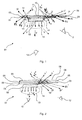
- light emitted by at least one light source of the luminous means 01 emits light to fulfill a light function while observing a defined emission characteristic in at least one of arrows V in Fig. 1, Fig. 2 . Fig. 5 and Fig. 7 directed preferred direction.
- light emitted by at least one light source of the illuminant 01 differs diffusely from the defined emission characteristic from the signal function element 02.
- the emission characteristic is defined, for example, by legal requirements or regulations for a light function to be performed by the light source.
- the luminous means fulfills one or more light distributions prescribed for the light function, for example by the aforementioned legal requirements or regulations, in at least one preferred direction and luminance in this at least one preferred direction by light emitted by at least one light source of the illuminant 01 in prescribed luminance distribution in the at least one prescribed preferred direction V exits the signal functional element.
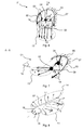
- the imaging means 03 is used for a targeted generation of a Fig. 6 and Fig. 7 shown in view from at least one preferred direction V visible image 04 differs from the defined radiation characteristic diffused scattered from the signal function element 02 light exiting.
- the imaging means 03 comprises at least one optical element 05 which generates the image 04 of the diffusely scattered light emerging from the signal function element 02 when viewed from the direction of at least one preferred direction V.
- the optical element 05 can be formed by a plane plate arrangement 06 and / or by a mirror plate arrangement 07. Alternatively or additionally, the optical element 05 may comprise a lens arrangement consisting of one or more optical lenses.
- the imaging means 03 may comprise at least one flat plate arrangement 06 and / or a mirror surface arrangement 07.
- a planar plate arrangement 06 may comprise one or more plane plates 08 of a material which is transparent at least in the wavelength range visible to the human eye, for example of a plastic, such as PMMA (polymethyl methacrylate).
- a plastic such as PMMA (polymethyl methacrylate).
- the at least one plane plate 08 may be mirrored on its front side facing the signal functional element 02 10 or on its rear side facing away from the signal function element 02, for example, by a Metallisches vaporization and thus be provided with a mirror surface 09, whereby the flat plate assembly 06 to the mirror surface assembly 07 or simultaneously properties a mirror surface arrangement 07 has.
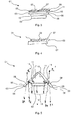
- an elliptical mirror surface 09 is provided as part of a mirror surface arrangement 07 for the imaging means 03.
- One or more plane plates 08 can, as in Fig. 1, Fig. 2 and Fig. 5 have shown total reflective properties. This can be realized using a transparent material with a suitable refractive index for the plane plate 08 or plane plates 08.
- the one or more plane plates 08 may be arranged in an angle given by the optical material properties of the transparent material and of the surrounding medium, typically air, and thus by the ratio of the refractive indices relative to one or more preferred directions V. which is desired to see a Figure 04 diffused scattered from the signal function element 02 emerging light.
- One or more plane plates 08 with total reflecting properties may additionally be mirrored on their rear side 11 facing away from the signal function element 02.
- the image 04 diffused diffusely from the emission characteristic diffused light from the signal function element 02 is thereby as based on the Fig. 1, Fig. 2 Fig. 5 . Fig. 6 and Fig. 7 explained generated.
- a main luminance image 13 which emerges in compliance with a defined radiation characteristic of a light function in at least one preferred direction V emitted from a signal function element 02 of the light source 01, and a sub-luminance image 14, the deviating from the diffused scattering characteristic of the light function emerges diffused from the signal function element 02.
- the secondary luminance image 14, which initially does not act in a preferred direction V, is imaged such that it is visible when viewed from the direction of at least one preferred direction V.
- Fig. 2 and Fig. 5 illustrated bulbs 01 with Planplatten 08 with total reflective properties comprehensive flat plate assemblies 06 are hereinafter differs as Figure 04 differs from the radiation pattern diffused from the signal function element 02 emerging light S1, S2 of the sub-luminance image 14 two reflection images R1, R2 generates.
- the transparent material for the plane plates 08 is thereby for example PMMA.
- the reflection image R1 is reflected rays on the front side 10 of the plane-parallel plate 8, at which a refraction at the transition of the surrounding medium air to the transparent material PMMA or glass of the plane plate 08 for the remaining, non-reflected part of the light S1, S2 he follows.
- the light which has penetrated into the plane plate 08 is then reflected on the rear side 11 1 of the plane plate 08 during the transition PMMA-air, whereby the reflexbile R2 is formed as a so-called backreflection image of the plane plate 08, in contrast to a reflection formed by the reflection image R1 at the entrance surface on the front side 10 of the plane plate 08 resulting front reflex image.
- the pixel P12 'in Fig. 1 arises by virtue of virtual beam combination of the reflection images R3 and R4 generated by multiple total reflection with the exit of a respective part of the light S3, S4 totally reflected in the plane plate 08.
- the pixel P21 'in Fig. 1 arises by virtue of the virtual beam combination of the reflection images R1 and R2 generated on the back 11 of the plane plate 08 by reflection of light S1, S2 diffused into the plane plate 08 and scattered diffusely by the emission characteristic 02.
- the pixel P11 "in Fig. 2 arises after multiple total reflection in the front plane plate 08 from the beam combination of R1 'and R2', which are formed by the proportions of the two object beams that pass the front of the two parallel plane plates 08 according to the law of refraction and then on the back 11 of the plane plate 08th be reflected. Then they go through again plan plate 08, to then be virtually united by the eye 12. The intensity of this pixel P1 "is then weaker than the pixel P11 '.
- the pixels P1 'and P2' in Fig. 5 arise in accordance with the pixel P21 'in Fig. 1 by virtue of the virtual beam combination of the light images S1, S2, which have diffused diffused by the reflection of planing plates 08 and diffused diffuse from the emission characteristic 02, on the rear side 11 of the plane plates 08.
- the reflection images R1, R2, R1 ', R2' individually perceived or form a unit with the Main luminance image 13.
- Two or more plane plates 08 and / or mirror surfaces 09 of a flat plate arrangement 06 and / or a mirror arrangement 07 can, as in FIG Fig. 5 shown in a cross section, for example, be arranged V-shaped. Other arrangements are possible. Also are in Fig. 2 and Fig. 3 illustrated combinations conceivable in which two flat plates 08 are arranged in transparent material lying parallel to each other in succession ( Fig. 2 ), or in which a mirror surface 09 is provided behind one or more parallel plane plates 08 made of transparent material ( Fig. 3 ).
- mirror surfaces 09 as imaging means 03 is as in the Fig. 4 .
- Fig. 6 and Fig. 7 shown possible.
- pixels F1 ' are formed by reflection at the mirror surface 09.
- the at least one signal function element 02 may comprise at least one light exit region of at least one light source and / or at least one light guide 15 associated with at least one light source and / or at least one primary optic of at least one light source of the light source 01.
- a signal functional element 02 embodied as a light exit region of a light guide 15 or comprising a light guide 15 can, as in FIG Fig. 8 represented as a so-called round light guide in the form of a bar light guide designed for example with a circular cross-section.
- the light exit region may comprise one or more light outcoupling surfaces 17 that are different from a light coupling surface 16 of the light guide 15.
- the coupling out of the light guide 15 may be provided in all radial directions, such as by the light guide having a rough surface.
- the light outcoupling surface encompassed by the light exit region takes up the entire circular cylindrical surface of the lamp Optical fiber 15 a.
- the light coupling can be provided on one or both sides, for example on opposite end faces 18 of the optical waveguide 15 designed as a bar light guide.
- the illuminant described is particularly suitable for use in a motor vehicle lamp designed preferably as a motor vehicle tail lamp with a lamp housing enclosed by a lamp housing and a preferably clear lens.
- a motor vehicle lamp designed preferably as a motor vehicle tail lamp with a lamp housing enclosed by a lamp housing and a preferably clear lens.
- the lamp interior which is subdivided, for example, into one or more lamp chambers, at least one illuminating means previously described for carrying out at least one light function of the motor vehicle tail lamp is arranged.
- the invention is industrially applicable in particular in the field of the production of motor vehicle lights as well as bulbs.
Landscapes
- Engineering & Computer Science (AREA)
- General Engineering & Computer Science (AREA)
- Non-Portable Lighting Devices Or Systems Thereof (AREA)
Priority Applications (1)
| Application Number | Priority Date | Filing Date | Title |
|---|---|---|---|
| EP11177700A EP2559934A1 (fr) | 2011-08-16 | 2011-08-16 | Moyen d'éclairage, lampe de véhicule automobile et procédé de production d'une fonction d'éclairage |
Applications Claiming Priority (1)
| Application Number | Priority Date | Filing Date | Title |
|---|---|---|---|
| EP11177700A EP2559934A1 (fr) | 2011-08-16 | 2011-08-16 | Moyen d'éclairage, lampe de véhicule automobile et procédé de production d'une fonction d'éclairage |
Publications (1)
| Publication Number | Publication Date |
|---|---|
| EP2559934A1 true EP2559934A1 (fr) | 2013-02-20 |
Family
ID=44677503
Family Applications (1)
| Application Number | Title | Priority Date | Filing Date |
|---|---|---|---|
| EP11177700A Withdrawn EP2559934A1 (fr) | 2011-08-16 | 2011-08-16 | Moyen d'éclairage, lampe de véhicule automobile et procédé de production d'une fonction d'éclairage |
Country Status (1)
| Country | Link |
|---|---|
| EP (1) | EP2559934A1 (fr) |
Citations (7)
| Publication number | Priority date | Publication date | Assignee | Title |
|---|---|---|---|---|
| US20040184286A1 (en) * | 2003-01-30 | 2004-09-23 | Antoine De Lamberterie | Light guide equipped with reflectors |
| US6953271B2 (en) * | 2002-10-28 | 2005-10-11 | Valeo Vision | Indicator lamp comprising an optical device for recovering and distributing the light flux towards an annular reflector |
| EP1657111A2 (fr) * | 2004-11-15 | 2006-05-17 | FER Fahrzeugelektrik GmbH | Feu latéral clignotant |
| EP1953451A2 (fr) * | 2007-01-31 | 2008-08-06 | Stanley Electric Co., Ltd. | Unité d'éclairage à DEL et lampe de véhicule |
| DE102007005779A1 (de) * | 2007-02-06 | 2008-08-07 | Automotive Lighting Reutlingen Gmbh | Beleuchtungseinrichtung für ein Fahrzeug und Scheinwerfer mit einer solchen Beleuchtungseinrichtung |
| FR2934353A1 (fr) * | 2008-07-25 | 2010-01-29 | Valeo Vision Sas | Systeme optique avec fonction d'eclairage a large surface d'emission pour vehicule automobile |
| DE102008038668A1 (de) * | 2008-08-12 | 2010-02-18 | Hella Kgaa Hueck & Co. | Signalleuchte für Fahrzeuge |
-
2011
- 2011-08-16 EP EP11177700A patent/EP2559934A1/fr not_active Withdrawn
Patent Citations (7)
| Publication number | Priority date | Publication date | Assignee | Title |
|---|---|---|---|---|
| US6953271B2 (en) * | 2002-10-28 | 2005-10-11 | Valeo Vision | Indicator lamp comprising an optical device for recovering and distributing the light flux towards an annular reflector |
| US20040184286A1 (en) * | 2003-01-30 | 2004-09-23 | Antoine De Lamberterie | Light guide equipped with reflectors |
| EP1657111A2 (fr) * | 2004-11-15 | 2006-05-17 | FER Fahrzeugelektrik GmbH | Feu latéral clignotant |
| EP1953451A2 (fr) * | 2007-01-31 | 2008-08-06 | Stanley Electric Co., Ltd. | Unité d'éclairage à DEL et lampe de véhicule |
| DE102007005779A1 (de) * | 2007-02-06 | 2008-08-07 | Automotive Lighting Reutlingen Gmbh | Beleuchtungseinrichtung für ein Fahrzeug und Scheinwerfer mit einer solchen Beleuchtungseinrichtung |
| FR2934353A1 (fr) * | 2008-07-25 | 2010-01-29 | Valeo Vision Sas | Systeme optique avec fonction d'eclairage a large surface d'emission pour vehicule automobile |
| DE102008038668A1 (de) * | 2008-08-12 | 2010-02-18 | Hella Kgaa Hueck & Co. | Signalleuchte für Fahrzeuge |
Similar Documents
| Publication | Publication Date | Title |
|---|---|---|
| EP2587120B1 (fr) | Conduit de lumière et vèhicule automobile muni d'un tel conduit de lumière | |
| DE102009022726B4 (de) | Von der Rückseite anzubringendes Leuchtdioden-Modul für Kombinationsrücklichter an Kraftfahrzeugen | |
| DE102012221389B4 (de) | Kraftfahrzeugleuchte mit einem Lichtleiter und einer durch den Lichtleiter hindurch sichtbaren Blende | |
| DE102014205994B4 (de) | Lichtmodul mit Halbleiterlichtquelle und Vorsatzoptik und Kraftfahrzeugscheinwerfer mit einem solchen Lichtmodul | |
| DE102012202508B4 (de) | Lichtleitervorrichtung für eine Kraftfahrzeugleuchte | |
| DE102012112075A1 (de) | Beleuchtungsvorrichtung für Fahrzeuge | |
| AT517394B1 (de) | Beleuchtungseinrichtung für ein Kraftfahrzeug mit lumineszierenden Elementen | |
| EP2770247B1 (fr) | Phare de véhicule automobile ayant une apparence lumineuse claire homogène | |
| DE102011000022A1 (de) | Leuchteinheit für Fahrzeuge | |
| DE202021103908U1 (de) | Leuchte für ein Fahrzeug | |
| EP2384934A1 (fr) | Lampe de véhicule automobile avec plusieurs fonctions d'éclairage | |
| DE102017127663A1 (de) | Leuchtvorrichtung, insbesondere eine Signalleuchte für Kraftfahrzeuge | |
| DE102005040100B4 (de) | Fahrzeugleuchte mit einem ersten Leuchtenfunktionsbereich und wenigstens einem weiteren Leuchtenfunktionsbereich in Trennbereichen zwischen durchleuchtbaren, lichtstreuende Mittel aufweisenden Leuchtkörpern für den ersten Leuchtenfunktionsbereich | |
| EP2543540A1 (fr) | Conducteur lumineux, moyen d'éclairage et éclairage de véhicule automobile | |
| DE102014116983B4 (de) | Laseroptisches system für einen fahrzeug-frontscheinwerfer, bei dem eine einen laserstrahl fokussierende strahllinse in unmittelbarem kontakt mit einem vom laserstrahl angeregten leuchtkörper ist | |
| DE102013007856A1 (de) | Lichtleitkörper und Leuchtvorrichtung mit dem Lichtleitkörper | |
| EP4113001A1 (fr) | Module d'éclairage pour dispositif d'éclairage d'un véhicule et procédé de réduction d'une désaturation de la couleur dans un module d'éclairage pour un dispositif d'éclairage d'un véhicule | |
| DE102012103368A1 (de) | Beleuchtungsvorrichtung für Fahrzeuge | |
| DE102013210257A1 (de) | Vorsatzoptik für eine Lichtquelle | |
| EP2589859A1 (fr) | Lampe de véhicule automobile | |
| DE102013110344B4 (de) | Beleuchtungsvorrichtung für Fahrzeuge zur Erzeugung von Schlusslicht- und Nebelschlusslichtfunktionen | |
| EP2743565B1 (fr) | Dispositif d'éclairage avec un élément conducteur de lumière en forme de doigt et un réflecteur comportant deux facettes | |
| DE102010055332A1 (de) | Leuchteinrichtung für ein Fahrzeug | |
| EP4370364A1 (fr) | Dispositif d'éclairage holographique | |
| EP3839328A1 (fr) | Moyen d'éclairage pourvu de combinaison de fonction d'éclairage et de rétroréflecteur ainsi que lampe pour véhicule équipée d'un tel moyen d'éclairage |
Legal Events
| Date | Code | Title | Description |
|---|---|---|---|
| PUAI | Public reference made under article 153(3) epc to a published international application that has entered the european phase |
Free format text: ORIGINAL CODE: 0009012 |
|
| AK | Designated contracting states |
Kind code of ref document: A1 Designated state(s): AL AT BE BG CH CY CZ DE DK EE ES FI FR GB GR HR HU IE IS IT LI LT LU LV MC MK MT NL NO PL PT RO RS SE SI SK SM TR |
|
| AX | Request for extension of the european patent |
Extension state: BA ME |
|
| STAA | Information on the status of an ep patent application or granted ep patent |
Free format text: STATUS: THE APPLICATION IS DEEMED TO BE WITHDRAWN |
|
| 18D | Application deemed to be withdrawn |
Effective date: 20130821 |