EP2559947B1 - Mikromischerhitzeschild - Google Patents
Mikromischerhitzeschild Download PDFInfo
- Publication number
- EP2559947B1 EP2559947B1 EP12179888.8A EP12179888A EP2559947B1 EP 2559947 B1 EP2559947 B1 EP 2559947B1 EP 12179888 A EP12179888 A EP 12179888A EP 2559947 B1 EP2559947 B1 EP 2559947B1
- Authority
- EP
- European Patent Office
- Prior art keywords
- fuel
- accordance
- fuel nozzle
- outer sleeve
- baffle plate
- Prior art date
- Legal status (The legal status is an assumption and is not a legal conclusion. Google has not performed a legal analysis and makes no representation as to the accuracy of the status listed.)
- Not-in-force
Links
- 239000000446 fuel Substances 0.000 claims description 91
- 238000002156 mixing Methods 0.000 claims description 32
- 238000002347 injection Methods 0.000 claims description 21
- 239000007924 injection Substances 0.000 claims description 21
- 238000002485 combustion reaction Methods 0.000 claims description 16
- 238000011144 upstream manufacturing Methods 0.000 claims description 14
- 238000000034 method Methods 0.000 claims description 11
- 230000005465 channeling Effects 0.000 claims description 6
- 239000003570 air Substances 0.000 description 20
- 239000000203 mixture Substances 0.000 description 7
- 238000001816 cooling Methods 0.000 description 5
- 230000006870 function Effects 0.000 description 5
- 230000008646 thermal stress Effects 0.000 description 4
- 239000000567 combustion gas Substances 0.000 description 3
- 239000012080 ambient air Substances 0.000 description 2
- 230000000712 assembly Effects 0.000 description 1
- 238000000429 assembly Methods 0.000 description 1
- 239000000919 ceramic Substances 0.000 description 1
- 230000007717 exclusion Effects 0.000 description 1
- 239000000284 extract Substances 0.000 description 1
- 239000007789 gas Substances 0.000 description 1
- 239000000463 material Substances 0.000 description 1
- 230000002028 premature Effects 0.000 description 1
- 239000012720 thermal barrier coating Substances 0.000 description 1
Images

Classifications
-
- F—MECHANICAL ENGINEERING; LIGHTING; HEATING; WEAPONS; BLASTING
- F23—COMBUSTION APPARATUS; COMBUSTION PROCESSES
- F23R—GENERATING COMBUSTION PRODUCTS OF HIGH PRESSURE OR HIGH VELOCITY, e.g. GAS-TURBINE COMBUSTION CHAMBERS
- F23R3/00—Continuous combustion chambers using liquid or gaseous fuel
- F23R3/28—Continuous combustion chambers using liquid or gaseous fuel characterised by the fuel supply
- F23R3/286—Continuous combustion chambers using liquid or gaseous fuel characterised by the fuel supply having fuel-air premixing devices
-
- F—MECHANICAL ENGINEERING; LIGHTING; HEATING; WEAPONS; BLASTING
- F23—COMBUSTION APPARATUS; COMBUSTION PROCESSES
- F23R—GENERATING COMBUSTION PRODUCTS OF HIGH PRESSURE OR HIGH VELOCITY, e.g. GAS-TURBINE COMBUSTION CHAMBERS
- F23R2900/00—Special features of, or arrangements for continuous combustion chambers; Combustion processes therefor
- F23R2900/00002—Gas turbine combustors adapted for fuels having low heating value [LHV]
-
- F—MECHANICAL ENGINEERING; LIGHTING; HEATING; WEAPONS; BLASTING
- F23—COMBUSTION APPARATUS; COMBUSTION PROCESSES
- F23R—GENERATING COMBUSTION PRODUCTS OF HIGH PRESSURE OR HIGH VELOCITY, e.g. GAS-TURBINE COMBUSTION CHAMBERS
- F23R3/00—Continuous combustion chambers using liquid or gaseous fuel
- F23R3/42—Continuous combustion chambers using liquid or gaseous fuel characterised by the arrangement or form of the flame tubes or combustion chambers
- F23R3/46—Combustion chambers comprising an annular arrangement of several essentially tubular flame tubes within a common annular casing or within individual casings
- F23R3/48—Flame tube interconnectors, e.g. cross-over tubes
Definitions
- the present disclosure relates generally to a turbine system and more particularly to a micromixer fuel nozzle that may be used with a turbine system.
- Some known turbine systems include at least one combustor assembly that mixes compressed air with fuel and ignites the fuel-air mixture to generate combustion gases within a combustion zone defined in the combustor assembly. More specifically, at least some known combustor assemblies use a micromixer that includes an outer sleeve that is oriented to channel air and/or fuel towards the combustion zone and an aft face that is positioned adjacent to the combustion zone. As a result, the aft face is exposed to the relatively high temperatures generated within the combustion zone.
- At least some known micromixers channel air and/or fuel towards the combustion zone at a relatively high velocity. Channeling the air and/or fuel at such a velocity ensures that energy losses within the air and/or fuel are minimized, but results in a forced convective cooling of the outer sleeve. As such, thermal gradients and/or thermal stresses may develop within at least some known micromixers. Over cycles, such thermal gradients and/or thermal stresses may limit the useful life of portions of the micromixer and/or may lead to a premature failure of such components.
- US 2011/0073684 discloses a fuel nozzle with internal baffling.
- the invention provides, a method for preparing a turbine engine for operation.
- the method includes channeling fuel between a baffle plate and an aft face of a fuel nozzle.
- the baffle plate is between a forward face and the aft face of the fuel nozzle.
- the fuel is channeled toward a heat shield and between a plurality of mixing tubes extending between the forward face and the aft face.
- the fuel is channeled through an injection opening defined in a sidewall forming at least one of the plurality of mixing tubes.
- the invention provides a fuel nozzle comprising: a forward face; an aft face downstream from said forward face; a plurality of mixing tubes extending between said forward face and said aft face, wherein at least one of said plurality of mixing tubes comprises a sidewall that includes an injection opening defined therethrough; an outer sleeve positioned radially outward of said plurality of mixing tubes; and a baffle plate between said forward face and said aft face, wherein said baffle plate is oriented to channel fuel between said plurality of mixing tubes and between said baffle plate and said aft face prior to the fuel being channeled through the injection opening; characterized by: a heat shield positioned radially inward of said outer sleeve and extending along an inner surface of said outer sleeve.
- the invention further provides a combustor.
- the combustor includes a combustor wall defining a combustion zone and a fuel nozzle as described above, wherein the aft face is adjacent to the combustion zone.
- a fuel nozzle includes a forward face, an aft face downstream from the forward face, a plurality of mixing tubes that extend between the forward and aft faces, an outer sleeve positioned radially outward of the plurality of mixing tubes, a heat shield positioned radially inward of the outer sleeve, and a baffle plate positioned between the forward and aft faces.
- the fuel nozzle channels fuel downstream through a center supply tube towards a space defined between the baffle plate and the aft face.
- the fuel is channeled radially outward through the space defined between the baffle plate and the aft face, and then the fuel is channeled upstream towards an injection opening defined in a mixing tube.
- the fuel is channeled through the injection opening, and then the fuel is mixed with air channeled through the mixing tube.
- the air-fuel mixture is channeled through the mixing tube towards a combustion zone defined in a combustor.
- the baffle plate and/or the heat shield regulate fuel and/or air flow within the fuel nozzle to facilitate reducing thermal stresses that may be generated within the fuel nozzle.
- axial and axially refer to directions and orientations extending substantially parallel to a longitudinal axis of a combustor.
- radial and radially refer to directions and orientations extending substantially perpendicular to the longitudinal axis of the combustor.
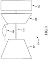
- FIG. 1 is a schematic illustration of an exemplary turbine system 100.
- turbine system 100 includes, coupled in a serial flow arrangement, a compressor 104, a combustor assembly 106, and a turbine 108 that is rotatably coupled to compressor 104 via a rotor shaft 110.
- turbine system 100 is a GE 7FB gas turbine commercially available from General Electric Company headquartered in Schenectady, New York.
- ambient air is channeled through an air inlet (not shown) towards compressor 104.
- the ambient air is compressed by compressor 104 prior to being channeled towards combustor assembly.
- compressed air within combustor assembly 106 is mixed with fuel, and the resulting fuel-air mixture is ignited within combustor assembly 106 or, more specifically, a combustion zone (not shown in FIG. 1 ) to generate combustion gases that are channeled towards turbine 108.
- turbine 108 extracts rotational energy from the combustion gases and rotates rotor shaft 110 to drive compressor 104.
- turbine system 100 drives a load 112, such as a generator, coupled to rotor shaft 110.
- load 112 is downstream of turbine system 100.
- load 112 may be positioned upstream of turbine system 100.
- FIG. 2 is a perspective view of a portion of a micromixer or, more broadly, a fuel nozzle 200 that may be used with combustor assembly 106 to mix compressed air with fuel to create a combustible air-fuel mixture.
- fuel nozzle 200 is positioned upstream from a combustion zone 210 defined within combustor assembly 106 to enable the air-fuel mixture to be channeled through fuel nozzle 200 and ignited within combustion zone 210.
- fuel nozzle 200 includes a forward face 220, an aft face 230 that is positioned axially downstream from forward face 220, and an outer sleeve 240 that extends between forward and aft faces 220 and 230 such that a cavity 250 is defined therein.
- fuel nozzle 200 includes a heat shield 260 that is positioned radially inward of outer sleeve 240 and extends along an inner surface of outer sleeve 240 to facilitate reducing a convection cooling of outer sleeve 240.
- Heat shield 260 may be fabricated from any material such as, without limitation, a ceramic that enables heat shield 260 to function as described herein.
- heat shield 260 defines an annular gap 270 therebetween.
- gap 270 facilitates further reducing a heat transfer between outer sleeve 240 and the fuel and/or air channeled through fuel nozzle 200.
- gap 270 insulates outer sleeve 240 from fuel and/or air being channeled through fuel nozzle 200.
- heat shield 260 may be any structure, feature, and/or element that enables fuel nozzle 200 to function as described herein.
- heat shield 260 may be a thermal barrier coating applied to an inner surface of outer sleeve 240. Any insulating mechanism may be positioned and/or disposed between heat shield 260 and outer sleeve 240 that enables heat shield 260 to function as described herein.
- a center supply tube 280 extends through forward face 220.
- Tube 280 is oriented to channel fuel downstream towards aft face 230.
- center supply tube 280 extends generally axially through cavity 250 between forward and aft faces 220 and 230. More specifically, in the exemplary embodiment, center supply tube 280 is aligned substantially coaxially with fuel nozzle 200 and extends substantially along a longitudinal axis 290 of fuel nozzle 200.
- a baffle plate 300 is positioned between forward and aft faces 220 and 230. More specifically, in the exemplary embodiment, baffle plate 300 extends generally radially outward from a downstream end 310 of center supply tube 280. Baffle plate 300 is oriented to channel fuel from center supply tube 280 and radially outward through a space 305 defined between baffle plate 300 and aft face 230. More specifically, in the exemplary embodiment, fuel is channeled radially outward through space 305 between adjacent mixing tubes 320 towards heat shield 260 and outer sleeve 240.
- each mixing tube 320 extends generally axially through cavity 250 between forward face 220 and aft face 230. More specifically, in the exemplary embodiment, each mixing tube 320 includes an upstream opening 330 that is defined in forward face 220 and a downstream opening 340 that is defined in aft face 230. Tubes 320 are oriented to channel air and/or fuel axially towards combustion zone 210. Moreover, in the exemplary embodiment, each mixing tube 320 extends through baffle plate 300 such that mixing tubes 320 extend a distance upstream and downstream from baffle plate 300.
- baffle plate 300 Downstream from baffle plate 300, fuel is channeled radially outward from tube 280 towards heat shield 260 and/or outer sleeve 240, and upstream of baffle plate 300, fuel is channeled radially inward towards mixing tubes 320.
- each mixing tube 320 includes a sidewall 350 that includes an injection opening 360 defined therein.
- sidewall 350 includes a plurality of injection openings 360 defined therein.
- Sidewall 350 may have any number of injection openings 360 defined therein that enables fuel nozzle 200 to function as described herein.
- Each opening 360 is oriented to inject fuel from cavity 250 into mixing tube 320.
- the fuel injected through injection opening 360 mixes with air channeled through a respective mixing tube 320 from upstream opening 330.
- each injection opening 360 divides a respective mixing tube 320 into an upstream portion 370 in which air is channeled therethrough and a downstream portion 380 in which an air-fuel mixture is channeled therethrough.
- fuel is channeled downstream through center supply tube 280 prior to being channeled radially outward through space 305.
- the fuel flow facilitates convectively cooling aft face 230.
- the fuel is then channeled radially outward through space 305. More specifically, in the exemplary embodiment, the fuel is channeled radially outward towards heat shield 260 and/or outer sleeve 240 between adjacent mixing tubes 320.
- fuel is channeled upstream through cavity 250 towards those portions of mixing tubes 320 that are upstream from baffle plate 300.
- the fuel is then channeled through injection openings 360 and into each mixing tube 320, wherein the fuel is mixed with the air channeled through a respective upstream portion 370.
- the resulting air-fuel mixture is then channeled through downstream portions 380 and discharged into combustion zone 210.
- the exemplary methods and systems described herein enable fuel and/or air to be channeled through a fuel nozzle to regulate a temperature of the fuel nozzle.
- a fuel nozzle By channeling fuel and/or air downstream through a center supply tube, radially outward between a baffle plate and aft face, and upstream towards an injection opening radially inward of a heat shield, convection cooling of the outer sleeve is reduced, thereby reducing a thermal gradient between the outer sleeve and the aft face.
- the cooling of the aft face reduces thermal stresses within the fuel nozzle, thereby increasing durability and/or robustness of the fuel nozzle.
- exemplary systems and methods are not limited to the specific embodiments described herein, but rather, components of each system and/or steps of each method may be utilized independently and separately from other components and/or method steps described herein. Each component and each method step may also be used in combination with other components and/or method steps.
Landscapes
- Engineering & Computer Science (AREA)
- Chemical & Material Sciences (AREA)
- Combustion & Propulsion (AREA)
- Mechanical Engineering (AREA)
- General Engineering & Computer Science (AREA)
- Spray-Type Burners (AREA)
- Gas Burners (AREA)
Claims (15)
- Kraftstoffdüse (200) umfassend:eine vordere Fläche (220);eine hintere Fläche (230) stromabwärts von der vorderen Fläche;eine Vielzahl von Mischrohren (320), die sich zwischen der vorderen Fläche und der hinteren Fläche erstrecken, wobei mindestens eines von der Vielzahl von Mischrohren eine Seitenwand (350) umfasst, die eine dort hindurch definierte Einspritzöffnung (310) aufweist;eine äußere Hülle (240), die radial außerhalb der Vielzahl von Mischrohren positioniert ist; undeine Leitwandplatte (300) zwischen der vorderen Fläche und der hinteren Fläche, wobei die Leitwandplatte so ausgerichtet ist, dass sie Kraftstoff zwischen der Vielzahl von Mischrohren und zwischen der Leitwandplatte und der hinteren Fläche leitet, bevor der Kraftstoff durch die Einspritzöffnung geleitet wird; gekennzeichnet durch:eine Hitzeabschirmung (260), die radial innerhalb der äußeren Hülle positioniert ist und sich entlang einer Innenfläche der äußeren Hülle erstreckt.
- Kraftstoffdüse nach Anspruch 1, weiter umfassend ein Zuführungsrohr (280), das so ausgerichtet ist, dass es den Kraftstoff stromabwärts zu der Leitwandplatte leitet, wobei das Zuführungsrohr im Wesentlichen innerhalb der Kraftstoffdüse zentriert ist.
- Kraftstoffdüse nach Anspruch 1 oder Anspruch 2, wobei ein ringförmiger Spalt (270) zwischen der äußeren Hülle und der Hitzeabschirmung definiert ist.
- Kraftstoffdüse nach einem vorstehenden Anspruch, wobei ein Isoliermechanismus radial innerhalb der äußeren Hülle positioniert ist.
- Kraftstoffdüse nach einem vorstehenden Anspruch, wobei mindestens eine von der äußeren Hülle und der Hitzeabschirmung so ausgerichtet ist, dass sie den Kraftstoff zu der Einspritzöffnung leitet.
- Kraftstoffdüse nach einem vorstehenden Anspruch, wobei sich die Einspritzöffnung stromaufwärts der Leitwandplatte befindet.
- Kraftstoffdüse nach einem vorstehenden Anspruch, wobei die Einspritzöffnung so ausgerichtet ist, dass sie den Kraftstoff stromabwärts durch mindestens eines der Vielzahl von Mischrohren leitet.
- Brennkammer (106) umfassend:eine Brennkammerwand, die eine Verbrennungszone (210) definiert; undeine Kraftstoffdüse (200) nach Anspruch 1, wobei die hintere Fläche (230) benachbart zu der Verbrennungszone ist.
- Brennkammer nach Anspruch 8, wobei die Kraftstoffdüse weiter ein zentrales Zuführungsrohr (280) umfasst, das so ausgerichtet ist, dass es den Kraftstoff stromabwärts zu der Leitwandplatte leitet, wobei das Zuführungsrohr im Wesentlichen innerhalb der Kraftstoffdüse zentriert ist.
- Brennkammer nach Anspruch 8 oder Anspruch 9, wobei ein ringförmiger Spalt (270) zwischen der äußeren Hülle und der Hitzeabschirmung definiert ist.
- Brennkammer nach einem der Ansprüche 8 bis 10, wobei ein Isoliermechanismus radial innerhalb der äußeren Hülle positioniert ist.
- Brennkammer nach einem der Ansprüche 8 bis 11, wobei mindestens eine von der äußeren Hülle und der Hitzeabschirmung so ausgerichtet ist, dass sie den Kraftstoff zu der Einspritzöffnung leitet.
- Brennkammer nach einem der Ansprüche 8 bis 12, wobei sich die Einspritzöffnung stromaufwärts von der Leitwandplatte befindet.
- Brennkammer nach einem der Ansprüche 8 bis 13, wobei die Einspritzöffnung so ausgerichtet ist, dass sie den Kraftstoff stromabwärts durch mindestens eines der Vielzahl von Mischrohren zu der Verbrennungszone leitet.
- Verfahren zum Vorbereiten eines Turbinentriebwerks für einen Betrieb, wobei das Turbinentriebwerk eine Brennkammer nach einem der Ansprüche 8-14 umfasst, wobei das Verfahren umfasst:Leiten von Kraftstoff zwischen der Leitwandplatte und der hinteren Fläche der Kraftstoffdüse,wobei sich die Leitwandplatte zwischen der vorderen Fläche und der hinteren Fläche der Kraftstoffdüse befindet;Leiten des Kraftstoffs zu der Hitzeabschirmung und zwischen die Vielzahl von Mischrohren, die sich zwischen der vorderen Fläche und der hinteren Fläche erstrecken; undLeiten des Kraftstoffs durch die Einspritzöffnung, die in der Seitenwand definiert ist, die mindestens eines der Vielzahl von Mischrohren bildet.
Applications Claiming Priority (1)
| Application Number | Priority Date | Filing Date | Title |
|---|---|---|---|
| US13/210,478 US8955327B2 (en) | 2011-08-16 | 2011-08-16 | Micromixer heat shield |
Publications (3)
| Publication Number | Publication Date |
|---|---|
| EP2559947A2 EP2559947A2 (de) | 2013-02-20 |
| EP2559947A3 EP2559947A3 (de) | 2017-02-01 |
| EP2559947B1 true EP2559947B1 (de) | 2019-06-05 |
Family
ID=46829630
Family Applications (1)
| Application Number | Title | Priority Date | Filing Date |
|---|---|---|---|
| EP12179888.8A Not-in-force EP2559947B1 (de) | 2011-08-16 | 2012-08-09 | Mikromischerhitzeschild |
Country Status (3)
| Country | Link |
|---|---|
| US (1) | US8955327B2 (de) |
| EP (1) | EP2559947B1 (de) |
| CN (1) | CN102954493B (de) |
Families Citing this family (23)
| Publication number | Priority date | Publication date | Assignee | Title |
|---|---|---|---|---|
| US9423135B2 (en) * | 2013-11-21 | 2016-08-23 | General Electric Company | Combustor having mixing tube bundle with baffle arrangement for directing fuel |
| US10101032B2 (en) | 2015-04-01 | 2018-10-16 | General Electric Company | Micromixer system for a turbine system and an associated method thereof |
| US10087844B2 (en) * | 2015-11-18 | 2018-10-02 | General Electric Company | Bundled tube fuel nozzle assembly with liquid fuel capability |
| US10393382B2 (en) | 2016-11-04 | 2019-08-27 | General Electric Company | Multi-point injection mini mixing fuel nozzle assembly |
| US10352569B2 (en) | 2016-11-04 | 2019-07-16 | General Electric Company | Multi-point centerbody injector mini mixing fuel nozzle assembly |
| US10295190B2 (en) | 2016-11-04 | 2019-05-21 | General Electric Company | Centerbody injector mini mixer fuel nozzle assembly |
| US10465909B2 (en) | 2016-11-04 | 2019-11-05 | General Electric Company | Mini mixing fuel nozzle assembly with mixing sleeve |
| US10724740B2 (en) | 2016-11-04 | 2020-07-28 | General Electric Company | Fuel nozzle assembly with impingement purge |
| US10634353B2 (en) | 2017-01-12 | 2020-04-28 | General Electric Company | Fuel nozzle assembly with micro channel cooling |
| JP6822894B2 (ja) | 2017-04-28 | 2021-01-27 | 三菱パワー株式会社 | 燃料噴射器及びガスタービン |
| JP6979343B2 (ja) | 2017-11-30 | 2021-12-15 | 三菱パワー株式会社 | 燃料噴射器、燃焼器、及びガスタービン |
| US10890329B2 (en) | 2018-03-01 | 2021-01-12 | General Electric Company | Fuel injector assembly for gas turbine engine |
| US11143406B2 (en) * | 2018-04-10 | 2021-10-12 | Delavan Inc. | Fuel injectors having air sealing structures |
| US11112117B2 (en) | 2018-07-17 | 2021-09-07 | General Electric Company | Fuel nozzle cooling structure |
| US10935245B2 (en) | 2018-11-20 | 2021-03-02 | General Electric Company | Annular concentric fuel nozzle assembly with annular depression and radial inlet ports |
| US11286884B2 (en) | 2018-12-12 | 2022-03-29 | General Electric Company | Combustion section and fuel injector assembly for a heat engine |
| US11073114B2 (en) | 2018-12-12 | 2021-07-27 | General Electric Company | Fuel injector assembly for a heat engine |
| US11156360B2 (en) | 2019-02-18 | 2021-10-26 | General Electric Company | Fuel nozzle assembly |
| KR102460001B1 (ko) * | 2021-02-17 | 2022-10-26 | 두산에너빌리티 주식회사 | 마이크로 믹서모듈 및 이를 포함하는 연소기 |
| WO2022249938A1 (ja) * | 2021-05-28 | 2022-12-01 | 川崎重工業株式会社 | ガスタービン燃焼器 |
| US12454909B2 (en) | 2021-12-03 | 2025-10-28 | General Electric Company | Combustor size rating for a gas turbine engine using hydrogen fuel |
| US12331932B2 (en) | 2022-01-31 | 2025-06-17 | General Electric Company | Turbine engine fuel mixer |
| US12215866B2 (en) | 2022-02-18 | 2025-02-04 | General Electric Company | Combustor for a turbine engine having a fuel-air mixer including a set of mixing passages |
Family Cites Families (15)
| Publication number | Priority date | Publication date | Assignee | Title |
|---|---|---|---|---|
| US4100733A (en) * | 1976-10-04 | 1978-07-18 | United Technologies Corporation | Premix combustor |
| US4313400A (en) | 1979-06-08 | 1982-02-02 | Amtrol Inc. | Lined metal tank with heat shield, indirect fired water heater and method of making same |
| US4351392A (en) | 1980-12-22 | 1982-09-28 | Combustion Engineering, Inc. | Heat exchange tube with heat absorptive shield |
| US5492168A (en) | 1994-07-18 | 1996-02-20 | Indugas, Inc. | High convective heat transfer immersion heater/cooler |
| US7509808B2 (en) * | 2005-03-25 | 2009-03-31 | General Electric Company | Apparatus having thermally isolated venturi tube joints |
| GB2451665B (en) * | 2007-08-08 | 2012-09-26 | Cilag Gmbh Int | Injection device |
| US8388308B2 (en) | 2007-10-30 | 2013-03-05 | General Electric Company | Asymmetric flow extraction system |
| US8112999B2 (en) * | 2008-08-05 | 2012-02-14 | General Electric Company | Turbomachine injection nozzle including a coolant delivery system |
| US9140454B2 (en) * | 2009-01-23 | 2015-09-22 | General Electric Company | Bundled multi-tube nozzle for a turbomachine |
| US8539773B2 (en) * | 2009-02-04 | 2013-09-24 | General Electric Company | Premixed direct injection nozzle for highly reactive fuels |
| US8424311B2 (en) * | 2009-02-27 | 2013-04-23 | General Electric Company | Premixed direct injection disk |
| US8157189B2 (en) * | 2009-04-03 | 2012-04-17 | General Electric Company | Premixing direct injector |
| US8181891B2 (en) * | 2009-09-08 | 2012-05-22 | General Electric Company | Monolithic fuel injector and related manufacturing method |
| US8794545B2 (en) * | 2009-09-25 | 2014-08-05 | General Electric Company | Internal baffling for fuel injector |
| US8276385B2 (en) * | 2009-10-08 | 2012-10-02 | General Electric Company | Staged multi-tube premixing injector |
-
2011
- 2011-08-16 US US13/210,478 patent/US8955327B2/en not_active Expired - Fee Related
-
2012
- 2012-08-09 EP EP12179888.8A patent/EP2559947B1/de not_active Not-in-force
- 2012-08-16 CN CN201210291871.4A patent/CN102954493B/zh not_active Expired - Fee Related
Non-Patent Citations (1)
| Title |
|---|
| None * |
Also Published As
| Publication number | Publication date |
|---|---|
| US8955327B2 (en) | 2015-02-17 |
| US20130042625A1 (en) | 2013-02-21 |
| EP2559947A3 (de) | 2017-02-01 |
| CN102954493A (zh) | 2013-03-06 |
| CN102954493B (zh) | 2015-11-25 |
| EP2559947A2 (de) | 2013-02-20 |
Similar Documents
| Publication | Publication Date | Title |
|---|---|---|
| US8955327B2 (en) | Micromixer heat shield | |
| US11274829B2 (en) | Shell and tiled liner arrangement for a combustor | |
| EP3055537B1 (de) | Brennkammerwand mit konischem kühlhohlraum | |
| US8438851B1 (en) | Combustor assembly for use in a turbine engine and methods of assembling same | |
| EP2925983B1 (de) | Gekühlte brennkammerdichtung | |
| US9140454B2 (en) | Bundled multi-tube nozzle for a turbomachine | |
| EP2481983B1 (de) | Turbulenz erzeugende Hinterkantenverkleidungsanordnung und Kühlungsverfahren für Gasturbinenbrennkammer | |
| US10041676B2 (en) | Sealed conical-flat dome for flight engine combustors | |
| US10317078B2 (en) | Cooling a multi-walled structure of a turbine engine | |
| CN101105293B (zh) | 有助于减少涡轮发动机中nox排放物的方法和装置 | |
| EP3220047B1 (de) | Gasturbinenstromhülsenhalterung | |
| EP2489937B1 (de) | Brennkammeranordnung zur Verwendung in einem Gasturbinenmotor und Herstellungsverfahren dafür | |
| CN103185354B (zh) | 用于冷却过渡喷嘴的方法和系统 | |
| US20120031099A1 (en) | Combustor assembly for use in a turbine engine and methods of assembling same | |
| US8813501B2 (en) | Combustor assemblies for use in turbine engines and methods of assembling same | |
| CN106989416A (zh) | 用于在燃烧器组件中使用的燃烧室衬套及制造方法 | |
| EP3077726B1 (de) | Kühlung eines brennkammerhitzeschilds in der nähe einer löschöffnung | |
| CN109416180B (zh) | 用于涡轮发动机中的燃烧器组件及其装配方法 | |
| EP4715264A1 (de) | Kühlung der abdeckung eines gasturbinenmotorbrennstoffzerstäubers |
Legal Events
| Date | Code | Title | Description |
|---|---|---|---|
| PUAI | Public reference made under article 153(3) epc to a published international application that has entered the european phase |
Free format text: ORIGINAL CODE: 0009012 |
|
| AK | Designated contracting states |
Kind code of ref document: A2 Designated state(s): AL AT BE BG CH CY CZ DE DK EE ES FI FR GB GR HR HU IE IS IT LI LT LU LV MC MK MT NL NO PL PT RO RS SE SI SK SM TR |
|
| AX | Request for extension of the european patent |
Extension state: BA ME |
|
| PUAL | Search report despatched |
Free format text: ORIGINAL CODE: 0009013 |
|
| AK | Designated contracting states |
Kind code of ref document: A3 Designated state(s): AL AT BE BG CH CY CZ DE DK EE ES FI FR GB GR HR HU IE IS IT LI LT LU LV MC MK MT NL NO PL PT RO RS SE SI SK SM TR |
|
| AX | Request for extension of the european patent |
Extension state: BA ME |
|
| RIC1 | Information provided on ipc code assigned before grant |
Ipc: F23R 3/28 20060101AFI20161223BHEP |
|
| STAA | Information on the status of an ep patent application or granted ep patent |
Free format text: STATUS: REQUEST FOR EXAMINATION WAS MADE |
|
| 17P | Request for examination filed |
Effective date: 20170801 |
|
| RBV | Designated contracting states (corrected) |
Designated state(s): AL AT BE BG CH CY CZ DE DK EE ES FI FR GB GR HR HU IE IS IT LI LT LU LV MC MK MT NL NO PL PT RO RS SE SI SK SM TR |
|
| STAA | Information on the status of an ep patent application or granted ep patent |
Free format text: STATUS: EXAMINATION IS IN PROGRESS |
|
| 17Q | First examination report despatched |
Effective date: 20180611 |
|
| GRAP | Despatch of communication of intention to grant a patent |
Free format text: ORIGINAL CODE: EPIDOSNIGR1 |
|
| STAA | Information on the status of an ep patent application or granted ep patent |
Free format text: STATUS: GRANT OF PATENT IS INTENDED |
|
| INTG | Intention to grant announced |
Effective date: 20190129 |
|
| GRAS | Grant fee paid |
Free format text: ORIGINAL CODE: EPIDOSNIGR3 |
|
| GRAA | (expected) grant |
Free format text: ORIGINAL CODE: 0009210 |
|
| STAA | Information on the status of an ep patent application or granted ep patent |
Free format text: STATUS: THE PATENT HAS BEEN GRANTED |
|
| AK | Designated contracting states |
Kind code of ref document: B1 Designated state(s): AL AT BE BG CH CY CZ DE DK EE ES FI FR GB GR HR HU IE IS IT LI LT LU LV MC MK MT NL NO PL PT RO RS SE SI SK SM TR |
|
| REG | Reference to a national code |
Ref country code: GB Ref legal event code: FG4D |
|
| REG | Reference to a national code |
Ref country code: CH Ref legal event code: EP |
|
| REG | Reference to a national code |
Ref country code: AT Ref legal event code: REF Ref document number: 1140390 Country of ref document: AT Kind code of ref document: T Effective date: 20190615 |
|
| REG | Reference to a national code |
Ref country code: IE Ref legal event code: FG4D |
|
| REG | Reference to a national code |
Ref country code: DE Ref legal event code: R096 Ref document number: 602012060668 Country of ref document: DE |
|
| REG | Reference to a national code |
Ref country code: NL Ref legal event code: MP Effective date: 20190605 |
|
| REG | Reference to a national code |
Ref country code: LT Ref legal event code: MG4D |
|
| PG25 | Lapsed in a contracting state [announced via postgrant information from national office to epo] |
Ref country code: ES Free format text: LAPSE BECAUSE OF FAILURE TO SUBMIT A TRANSLATION OF THE DESCRIPTION OR TO PAY THE FEE WITHIN THE PRESCRIBED TIME-LIMIT Effective date: 20190605 Ref country code: HR Free format text: LAPSE BECAUSE OF FAILURE TO SUBMIT A TRANSLATION OF THE DESCRIPTION OR TO PAY THE FEE WITHIN THE PRESCRIBED TIME-LIMIT Effective date: 20190605 Ref country code: AL Free format text: LAPSE BECAUSE OF FAILURE TO SUBMIT A TRANSLATION OF THE DESCRIPTION OR TO PAY THE FEE WITHIN THE PRESCRIBED TIME-LIMIT Effective date: 20190605 Ref country code: SE Free format text: LAPSE BECAUSE OF FAILURE TO SUBMIT A TRANSLATION OF THE DESCRIPTION OR TO PAY THE FEE WITHIN THE PRESCRIBED TIME-LIMIT Effective date: 20190605 Ref country code: NO Free format text: LAPSE BECAUSE OF FAILURE TO SUBMIT A TRANSLATION OF THE DESCRIPTION OR TO PAY THE FEE WITHIN THE PRESCRIBED TIME-LIMIT Effective date: 20190905 Ref country code: FI Free format text: LAPSE BECAUSE OF FAILURE TO SUBMIT A TRANSLATION OF THE DESCRIPTION OR TO PAY THE FEE WITHIN THE PRESCRIBED TIME-LIMIT Effective date: 20190605 Ref country code: LT Free format text: LAPSE BECAUSE OF FAILURE TO SUBMIT A TRANSLATION OF THE DESCRIPTION OR TO PAY THE FEE WITHIN THE PRESCRIBED TIME-LIMIT Effective date: 20190605 |
|
| PG25 | Lapsed in a contracting state [announced via postgrant information from national office to epo] |
Ref country code: RS Free format text: LAPSE BECAUSE OF FAILURE TO SUBMIT A TRANSLATION OF THE DESCRIPTION OR TO PAY THE FEE WITHIN THE PRESCRIBED TIME-LIMIT Effective date: 20190605 Ref country code: LV Free format text: LAPSE BECAUSE OF FAILURE TO SUBMIT A TRANSLATION OF THE DESCRIPTION OR TO PAY THE FEE WITHIN THE PRESCRIBED TIME-LIMIT Effective date: 20190605 Ref country code: BG Free format text: LAPSE BECAUSE OF FAILURE TO SUBMIT A TRANSLATION OF THE DESCRIPTION OR TO PAY THE FEE WITHIN THE PRESCRIBED TIME-LIMIT Effective date: 20190905 Ref country code: GR Free format text: LAPSE BECAUSE OF FAILURE TO SUBMIT A TRANSLATION OF THE DESCRIPTION OR TO PAY THE FEE WITHIN THE PRESCRIBED TIME-LIMIT Effective date: 20190906 |
|
| REG | Reference to a national code |
Ref country code: AT Ref legal event code: MK05 Ref document number: 1140390 Country of ref document: AT Kind code of ref document: T Effective date: 20190605 |
|
| PG25 | Lapsed in a contracting state [announced via postgrant information from national office to epo] |
Ref country code: PT Free format text: LAPSE BECAUSE OF FAILURE TO SUBMIT A TRANSLATION OF THE DESCRIPTION OR TO PAY THE FEE WITHIN THE PRESCRIBED TIME-LIMIT Effective date: 20191007 Ref country code: AT Free format text: LAPSE BECAUSE OF FAILURE TO SUBMIT A TRANSLATION OF THE DESCRIPTION OR TO PAY THE FEE WITHIN THE PRESCRIBED TIME-LIMIT Effective date: 20190605 Ref country code: EE Free format text: LAPSE BECAUSE OF FAILURE TO SUBMIT A TRANSLATION OF THE DESCRIPTION OR TO PAY THE FEE WITHIN THE PRESCRIBED TIME-LIMIT Effective date: 20190605 Ref country code: SK Free format text: LAPSE BECAUSE OF FAILURE TO SUBMIT A TRANSLATION OF THE DESCRIPTION OR TO PAY THE FEE WITHIN THE PRESCRIBED TIME-LIMIT Effective date: 20190605 Ref country code: RO Free format text: LAPSE BECAUSE OF FAILURE TO SUBMIT A TRANSLATION OF THE DESCRIPTION OR TO PAY THE FEE WITHIN THE PRESCRIBED TIME-LIMIT Effective date: 20190605 Ref country code: CZ Free format text: LAPSE BECAUSE OF FAILURE TO SUBMIT A TRANSLATION OF THE DESCRIPTION OR TO PAY THE FEE WITHIN THE PRESCRIBED TIME-LIMIT Effective date: 20190605 Ref country code: NL Free format text: LAPSE BECAUSE OF FAILURE TO SUBMIT A TRANSLATION OF THE DESCRIPTION OR TO PAY THE FEE WITHIN THE PRESCRIBED TIME-LIMIT Effective date: 20190605 |
|
| PG25 | Lapsed in a contracting state [announced via postgrant information from national office to epo] |
Ref country code: IT Free format text: LAPSE BECAUSE OF FAILURE TO SUBMIT A TRANSLATION OF THE DESCRIPTION OR TO PAY THE FEE WITHIN THE PRESCRIBED TIME-LIMIT Effective date: 20190605 Ref country code: SM Free format text: LAPSE BECAUSE OF FAILURE TO SUBMIT A TRANSLATION OF THE DESCRIPTION OR TO PAY THE FEE WITHIN THE PRESCRIBED TIME-LIMIT Effective date: 20190605 Ref country code: IS Free format text: LAPSE BECAUSE OF FAILURE TO SUBMIT A TRANSLATION OF THE DESCRIPTION OR TO PAY THE FEE WITHIN THE PRESCRIBED TIME-LIMIT Effective date: 20191005 |
|
| REG | Reference to a national code |
Ref country code: DE Ref legal event code: R097 Ref document number: 602012060668 Country of ref document: DE |
|
| PG25 | Lapsed in a contracting state [announced via postgrant information from national office to epo] |
Ref country code: TR Free format text: LAPSE BECAUSE OF FAILURE TO SUBMIT A TRANSLATION OF THE DESCRIPTION OR TO PAY THE FEE WITHIN THE PRESCRIBED TIME-LIMIT Effective date: 20190605 |
|
| PLBE | No opposition filed within time limit |
Free format text: ORIGINAL CODE: 0009261 |
|
| STAA | Information on the status of an ep patent application or granted ep patent |
Free format text: STATUS: NO OPPOSITION FILED WITHIN TIME LIMIT |
|
| PG25 | Lapsed in a contracting state [announced via postgrant information from national office to epo] |
Ref country code: PL Free format text: LAPSE BECAUSE OF FAILURE TO SUBMIT A TRANSLATION OF THE DESCRIPTION OR TO PAY THE FEE WITHIN THE PRESCRIBED TIME-LIMIT Effective date: 20190605 Ref country code: DK Free format text: LAPSE BECAUSE OF FAILURE TO SUBMIT A TRANSLATION OF THE DESCRIPTION OR TO PAY THE FEE WITHIN THE PRESCRIBED TIME-LIMIT Effective date: 20190605 |
|
| 26N | No opposition filed |
Effective date: 20200306 |
|
| PG25 | Lapsed in a contracting state [announced via postgrant information from national office to epo] |
Ref country code: LU Free format text: LAPSE BECAUSE OF NON-PAYMENT OF DUE FEES Effective date: 20190809 Ref country code: SI Free format text: LAPSE BECAUSE OF FAILURE TO SUBMIT A TRANSLATION OF THE DESCRIPTION OR TO PAY THE FEE WITHIN THE PRESCRIBED TIME-LIMIT Effective date: 20190605 Ref country code: CH Free format text: LAPSE BECAUSE OF NON-PAYMENT OF DUE FEES Effective date: 20190831 Ref country code: LI Free format text: LAPSE BECAUSE OF NON-PAYMENT OF DUE FEES Effective date: 20190831 Ref country code: MC Free format text: LAPSE BECAUSE OF FAILURE TO SUBMIT A TRANSLATION OF THE DESCRIPTION OR TO PAY THE FEE WITHIN THE PRESCRIBED TIME-LIMIT Effective date: 20190605 |
|
| REG | Reference to a national code |
Ref country code: BE Ref legal event code: MM Effective date: 20190831 |
|
| PG25 | Lapsed in a contracting state [announced via postgrant information from national office to epo] |
Ref country code: IE Free format text: LAPSE BECAUSE OF NON-PAYMENT OF DUE FEES Effective date: 20190809 Ref country code: FR Free format text: LAPSE BECAUSE OF NON-PAYMENT OF DUE FEES Effective date: 20190831 |
|
| PG25 | Lapsed in a contracting state [announced via postgrant information from national office to epo] |
Ref country code: BE Free format text: LAPSE BECAUSE OF NON-PAYMENT OF DUE FEES Effective date: 20190831 |
|
| GBPC | Gb: european patent ceased through non-payment of renewal fee |
Effective date: 20190905 |
|
| PG25 | Lapsed in a contracting state [announced via postgrant information from national office to epo] |
Ref country code: GB Free format text: LAPSE BECAUSE OF NON-PAYMENT OF DUE FEES Effective date: 20190905 |
|
| PG25 | Lapsed in a contracting state [announced via postgrant information from national office to epo] |
Ref country code: CY Free format text: LAPSE BECAUSE OF FAILURE TO SUBMIT A TRANSLATION OF THE DESCRIPTION OR TO PAY THE FEE WITHIN THE PRESCRIBED TIME-LIMIT Effective date: 20190605 |
|
| PG25 | Lapsed in a contracting state [announced via postgrant information from national office to epo] |
Ref country code: HU Free format text: LAPSE BECAUSE OF FAILURE TO SUBMIT A TRANSLATION OF THE DESCRIPTION OR TO PAY THE FEE WITHIN THE PRESCRIBED TIME-LIMIT; INVALID AB INITIO Effective date: 20120809 Ref country code: MT Free format text: LAPSE BECAUSE OF FAILURE TO SUBMIT A TRANSLATION OF THE DESCRIPTION OR TO PAY THE FEE WITHIN THE PRESCRIBED TIME-LIMIT Effective date: 20190605 |
|
| PGFP | Annual fee paid to national office [announced via postgrant information from national office to epo] |
Ref country code: DE Payment date: 20210720 Year of fee payment: 10 |
|
| PG25 | Lapsed in a contracting state [announced via postgrant information from national office to epo] |
Ref country code: MK Free format text: LAPSE BECAUSE OF FAILURE TO SUBMIT A TRANSLATION OF THE DESCRIPTION OR TO PAY THE FEE WITHIN THE PRESCRIBED TIME-LIMIT Effective date: 20190605 |
|
| REG | Reference to a national code |
Ref country code: DE Ref legal event code: R119 Ref document number: 602012060668 Country of ref document: DE |
|
| PG25 | Lapsed in a contracting state [announced via postgrant information from national office to epo] |
Ref country code: DE Free format text: LAPSE BECAUSE OF NON-PAYMENT OF DUE FEES Effective date: 20230301 |