EP2559960B1 - Kühlschrank und Steuerungsverfahren dafür - Google Patents
Kühlschrank und Steuerungsverfahren dafür Download PDFInfo
- Publication number
- EP2559960B1 EP2559960B1 EP12180410.8A EP12180410A EP2559960B1 EP 2559960 B1 EP2559960 B1 EP 2559960B1 EP 12180410 A EP12180410 A EP 12180410A EP 2559960 B1 EP2559960 B1 EP 2559960B1
- Authority
- EP
- European Patent Office
- Prior art keywords
- temperature
- cold air
- flow path
- refrigerator
- compartment
- Prior art date
- Legal status (The legal status is an assumption and is not a legal conclusion. Google has not performed a legal analysis and makes no representation as to the accuracy of the status listed.)
- Not-in-force
Links
Images


Classifications
-
- F—MECHANICAL ENGINEERING; LIGHTING; HEATING; WEAPONS; BLASTING
- F25—REFRIGERATION OR COOLING; COMBINED HEATING AND REFRIGERATION SYSTEMS; HEAT PUMP SYSTEMS; MANUFACTURE OR STORAGE OF ICE; LIQUEFACTION SOLIDIFICATION OF GASES
- F25D—REFRIGERATORS; COLD ROOMS; ICE-BOXES; COOLING OR FREEZING APPARATUS NOT OTHERWISE PROVIDED FOR
- F25D23/00—General constructional features
- F25D23/12—Arrangements of compartments additional to cooling compartments; Combinations of refrigerators with other equipment, e.g. stove
-
- F—MECHANICAL ENGINEERING; LIGHTING; HEATING; WEAPONS; BLASTING
- F25—REFRIGERATION OR COOLING; COMBINED HEATING AND REFRIGERATION SYSTEMS; HEAT PUMP SYSTEMS; MANUFACTURE OR STORAGE OF ICE; LIQUEFACTION SOLIDIFICATION OF GASES
- F25D—REFRIGERATORS; COLD ROOMS; ICE-BOXES; COOLING OR FREEZING APPARATUS NOT OTHERWISE PROVIDED FOR
- F25D17/00—Arrangements for circulating cooling fluids; Arrangements for circulating gas, e.g. air, within refrigerated spaces
- F25D17/04—Arrangements for circulating cooling fluids; Arrangements for circulating gas, e.g. air, within refrigerated spaces for circulating air, e.g. by convection
- F25D17/06—Arrangements for circulating cooling fluids; Arrangements for circulating gas, e.g. air, within refrigerated spaces for circulating air, e.g. by convection by forced circulation
- F25D17/062—Arrangements for circulating cooling fluids; Arrangements for circulating gas, e.g. air, within refrigerated spaces for circulating air, e.g. by convection by forced circulation in household refrigerators
- F25D17/065—Arrangements for circulating cooling fluids; Arrangements for circulating gas, e.g. air, within refrigerated spaces for circulating air, e.g. by convection by forced circulation in household refrigerators with compartments at different temperatures
-
- F—MECHANICAL ENGINEERING; LIGHTING; HEATING; WEAPONS; BLASTING
- F25—REFRIGERATION OR COOLING; COMBINED HEATING AND REFRIGERATION SYSTEMS; HEAT PUMP SYSTEMS; MANUFACTURE OR STORAGE OF ICE; LIQUEFACTION SOLIDIFICATION OF GASES
- F25D—REFRIGERATORS; COLD ROOMS; ICE-BOXES; COOLING OR FREEZING APPARATUS NOT OTHERWISE PROVIDED FOR
- F25D17/00—Arrangements for circulating cooling fluids; Arrangements for circulating gas, e.g. air, within refrigerated spaces
- F25D17/04—Arrangements for circulating cooling fluids; Arrangements for circulating gas, e.g. air, within refrigerated spaces for circulating air, e.g. by convection
- F25D17/06—Arrangements for circulating cooling fluids; Arrangements for circulating gas, e.g. air, within refrigerated spaces for circulating air, e.g. by convection by forced circulation
- F25D17/08—Arrangements for circulating cooling fluids; Arrangements for circulating gas, e.g. air, within refrigerated spaces for circulating air, e.g. by convection by forced circulation using ducts
-
- F—MECHANICAL ENGINEERING; LIGHTING; HEATING; WEAPONS; BLASTING
- F25—REFRIGERATION OR COOLING; COMBINED HEATING AND REFRIGERATION SYSTEMS; HEAT PUMP SYSTEMS; MANUFACTURE OR STORAGE OF ICE; LIQUEFACTION SOLIDIFICATION OF GASES
- F25D—REFRIGERATORS; COLD ROOMS; ICE-BOXES; COOLING OR FREEZING APPARATUS NOT OTHERWISE PROVIDED FOR
- F25D2317/00—Details or arrangements for circulating cooling fluids; Details or arrangements for circulating gas, e.g. air, within refrigerated spaces, not provided for in other groups of this subclass
- F25D2317/06—Details or arrangements for circulating cooling fluids; Details or arrangements for circulating gas, e.g. air, within refrigerated spaces, not provided for in other groups of this subclass with forced air circulation
- F25D2317/067—Details or arrangements for circulating cooling fluids; Details or arrangements for circulating gas, e.g. air, within refrigerated spaces, not provided for in other groups of this subclass with forced air circulation characterised by air ducts
-
- F—MECHANICAL ENGINEERING; LIGHTING; HEATING; WEAPONS; BLASTING
- F25—REFRIGERATION OR COOLING; COMBINED HEATING AND REFRIGERATION SYSTEMS; HEAT PUMP SYSTEMS; MANUFACTURE OR STORAGE OF ICE; LIQUEFACTION SOLIDIFICATION OF GASES
- F25D—REFRIGERATORS; COLD ROOMS; ICE-BOXES; COOLING OR FREEZING APPARATUS NOT OTHERWISE PROVIDED FOR
- F25D2317/00—Details or arrangements for circulating cooling fluids; Details or arrangements for circulating gas, e.g. air, within refrigerated spaces, not provided for in other groups of this subclass
- F25D2317/06—Details or arrangements for circulating cooling fluids; Details or arrangements for circulating gas, e.g. air, within refrigerated spaces, not provided for in other groups of this subclass with forced air circulation
- F25D2317/068—Details or arrangements for circulating cooling fluids; Details or arrangements for circulating gas, e.g. air, within refrigerated spaces, not provided for in other groups of this subclass with forced air circulation characterised by the fans
- F25D2317/0683—Details or arrangements for circulating cooling fluids; Details or arrangements for circulating gas, e.g. air, within refrigerated spaces, not provided for in other groups of this subclass with forced air circulation characterised by the fans the fans not of the axial type
-
- F—MECHANICAL ENGINEERING; LIGHTING; HEATING; WEAPONS; BLASTING
- F25—REFRIGERATION OR COOLING; COMBINED HEATING AND REFRIGERATION SYSTEMS; HEAT PUMP SYSTEMS; MANUFACTURE OR STORAGE OF ICE; LIQUEFACTION SOLIDIFICATION OF GASES
- F25D—REFRIGERATORS; COLD ROOMS; ICE-BOXES; COOLING OR FREEZING APPARATUS NOT OTHERWISE PROVIDED FOR
- F25D2400/00—General features of, or devices for refrigerators, cold rooms, ice-boxes, or for cooling or freezing apparatus not covered by any other subclass
- F25D2400/16—Convertible refrigerators
-
- F—MECHANICAL ENGINEERING; LIGHTING; HEATING; WEAPONS; BLASTING
- F25—REFRIGERATION OR COOLING; COMBINED HEATING AND REFRIGERATION SYSTEMS; HEAT PUMP SYSTEMS; MANUFACTURE OR STORAGE OF ICE; LIQUEFACTION SOLIDIFICATION OF GASES
- F25D—REFRIGERATORS; COLD ROOMS; ICE-BOXES; COOLING OR FREEZING APPARATUS NOT OTHERWISE PROVIDED FOR
- F25D2700/00—Means for sensing or measuring; Sensors therefor
- F25D2700/12—Sensors measuring the inside temperature
- F25D2700/121—Sensors measuring the inside temperature of particular compartments
-
- F—MECHANICAL ENGINEERING; LIGHTING; HEATING; WEAPONS; BLASTING
- F25—REFRIGERATION OR COOLING; COMBINED HEATING AND REFRIGERATION SYSTEMS; HEAT PUMP SYSTEMS; MANUFACTURE OR STORAGE OF ICE; LIQUEFACTION SOLIDIFICATION OF GASES
- F25D—REFRIGERATORS; COLD ROOMS; ICE-BOXES; COOLING OR FREEZING APPARATUS NOT OTHERWISE PROVIDED FOR
- F25D29/00—Arrangement or mounting of control or safety devices
Definitions
- the following description relates to a refrigerator having a storage compartment configured for a converted use as a freezing compartment or a refrigerating compartment.
- a refrigerator is an apparatus configured for keeping food fresh by using a cold air flow generated from a cooling cycle.
- a storage compartment of the refrigerator is divided into a refrigerating compartment configured to keep food refrigerated by maintaining the temperature at approximately 3° C, and a freezing compartment configured to keep food frozen by maintaining the temperature at approximately -20° C,
- the amount of the food stored in the refrigerating compartment is generally more than the amount of the food stored in the freezing compartment, and therefore, the refrigerating compartment is configured to be provided with a larger size than the freezing compartment. Also, because the refrigerating compartment is more frequently accessed, the refrigerating compartment is provided at a lower portion of the refrigerator while the freezing compartment is provided at an upper portion of the refrigerator.
- a cold air flow supply system of such refrigerator may be composed of in various methods. For example, a method to control the temperature of the freezing compartment at below 0° C and the temperature of the refrigerating compartment above 0° C by installing a damper apparatus at a cold air flow supply path for the refrigerating compartment and by adequately opening/closing the damper apparatus, while supplying the cold air flow generated from a single evaporating apparatus, is used.
- a refrigerator having the freezing compartment converted to the refrigerating compartment or the freezing compartment turned off for a use may be considered, and an example of such a refrigerator has been suggested in Korean patent publication No. 10-2010-0076089 .
- a refrigerator is provided with the damper apparatus configured to control the supply of the cold air flow to the freezing compartment and a means for heating the freezing compartment.
- This refrigerator is configured to limit the cold air flow supply to the freezing compartment by the use of the damper apparatus in order to convert the freezing compartment to the refrigerating compartment, and at the same time, to heat up the freezing compartment.
- this method consumes additional energy, thereby increasing costs.
- the invention provides a refrigerator according to one of the claims 1 to 14.
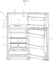
- FIG. 1 is a front view showing an inside structure of a refrigerator in accordance with an embodiment of the present disclosure
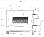
- FIG. 2 is a front view showing a structure of a converting compartment having a duct unit of a refrigerator of FIG. 1 separated in accordance with the embodiment of the present disclosure
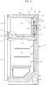
- FIG. 3 is a schematic side sectional view of the refrigerator of FIG. 1 .
- a refrigerator 1 includes a converting compartment 13 which is normally used for a freezing purpose.
- the converting compartment 13 is configured to also have a variable use for a refrigerating purpose or a turned off purpose
- the refrigerator 1 also includes a body 10 having a refrigerating compartment 14 formed at a lower side of the converting compartment 13.
- Each of the converting compartment 13 and the refrigerating compartment 14 is formed in a shape of having an open front surface, and the open front surface may be opened or closed by a converting compartment door 17 and a refrigerator door 18 that are hinge-coupled to the body 10.
- the converting compartment 13 and the refrigerating compartment 14 are divided by a mid wall 16, and an insulator is foamed at an inside of the mid wall 16, thereby a heat exchange is prevented between the converting compartment 13 and the refrigerating compartment 14.
- the converting compartment 13 is provided to have a smaller size than the refrigerating compartment 14, where a shelf 19 may be installed at an inside.
- a temperature sensor (not shown) is provided at an inside of each of the converting compartment 13 and the refrigerating compartment 14.
- the body 10 is composed of an inner case 11 configured to form the converting compartment 13 and the refrigerating compartment 14, an outer case 12 coupled to an outer side of the inner case 11 and configured to form an exterior of the refrigerator 1, and an insulation wall 25 formed while the insulator is foamed between the inner case 11 and the outer case 12.
- the converting compartment 13 is normally used for the freezing purpose, and therefore, having a thicker insulation wall 25 is preferred when compared to that of the refrigerating compartment 14.
- a cold air flow supplying apparatus 26 having a compressor 41, a condenser (not shown), an evaporator 40, and a refrigerating pipe (not shown) is provided in order to supply a cold air flow to such converting compartment 13 and refrigerating compartment 14.
- the compressor 41 is installed in a machinery room 43 provided at a lower portion of the body 10, and configured to compress the refrigerant with high pressure and high temperature using the rotary power of an electric motor, etc. by receiving supplied electric energy.
- the refrigerant compressed with the high temperature and high pressure is condensed while passing through the condenser (not shown) provided at the rear of the body 10, and becomes a liquid state having a low pressure and a low temperature while passing though an expanding valve (not shown).
- the evaporator 40 evaporates the liquid refrigerant having a low pressure and a low temperature passed through the expanding valve (not shown), and generates a cold air flow by cooling the surrounding air.
- the refrigerant that is completely evaporated is supplied to the compressor again for a cooling cycle to circulate.
- the evaporator 40 may be provided with a heating apparatus for a defrosting purpose (not shown).
- FIG. 2 illustrates a state that a duct unit 30, which is to be described later, is separated from the converting compartment 13, as illustrated on FIG. 2 , a settling unit 20 which is concaved toward a rear is formed at the rear inner case 11 of the converting compartment 13 in order for the evaporator 40 to be installed, thereby enabling the evaporator 40 being installed at the settling unit 20.
- the evaporator 40 is installed in a way of leaning toward one side direction from the settling unit 20 so that a rear flow path 72, which is to be described later, may be disposed at another side direction 15 of the settling unit 20.
- the evaporator 40 may be disposed at approximately one fourth below the converting compartment 13 in order for the cold air flow generated from the evaporator 40 to be directly fluidized to the refrigerating compartment 14 without passing through the duct unit 30.
- the cold air flow may be directly fluidized from the evaporator 40 to the refrigerating compartment 14, and thereby the temperature control is possible and the temperature of the refrigerating compartment 14 may be at the refrigerating temperature at a faster rate.
- the compressor 41 by compressing the refrigerant, pushes the refrigerant toward the condenser (not shown), and operates a cooling cycle which consists of a compression, a condensation, an expansion, and an evaporation. Therefore, when the compressor 41 is operated, the cold air flow generated at the evaporator 40 is supplied at the converting compartment 13 and the refrigerating compartment 14.
- the reference value of the operating time of the compressor 41 may be determined depending on the use of the converting compartment 13.
- the operating time of the compressor 41 is determined on the basis of the temperature of the converting compartment 13 as a reference value, and in a case that the converting compartment 13 is for refrigerating or turned off, the operating time of the compressor 41 is determined on the basis of the temperature of the refrigerating compartment 14 as a reference value.
- the compressor 41 is operated depending on whether the temperature of the converting compartment 13 is at the freezing temperature.
- the compressor 41 is operated depending on whether the temperature of the refrigerating compartment 14 is at the refrigerating temperature.
- the refrigerating temperature is approximately 3°C and the freezing temperature is approximately -20°C.
- the converting compartment 13 is for refrigerating or turned off, by having the temperature of the refrigerating compartment 14 as the reference for the operating time of the compressor 41, the supply of the cold air flow to the converting compartment 13 through the converting compartment damper apparatus 80, which is to be described later, and therefore, the cold air flow is continued to be supplied until the temperature of the refrigerating compartment 14 reaches the refrigerating temperature.
- the cold air flow supplying apparatus 26 further includes a distributing flow path 60 configured to distribute the cold air flow generated at the evaporator 40 to the converting compartment 13 and the refrigerating compartment 14, a converting compartment discharging flow path 70 configured to guide the cold air flow to the converting compartment 13, a refrigerating compartment discharging flow path 71 configured to guide the cold air flow to the refrigerating compartment, and an inlet flow path 74 to which the discharged cold air flow returns.
- the cold air flow supplying apparatus 26 further includes the duct unit 30 configured to divide the converting compartment 13 into a storage space 51 at the front and a cold air flow generating compartment 50 at the rear.
- the duct unit 30 forms the distributing flow path 60 at the inside while dividing the converting compartment 13.
- the structure of the duct unit 30, the distributing flow path 60, and the converting compartment discharging flow path 70 will be explained hereafter.
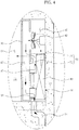
- FIG. 4 is an enlarged view illustrating a duct unit of the refrigerator of FIG. 3
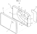
- FIG. 5 is an exploded perspective view illustrating a duct unit of a refrigerator in accordance with the embodiment of the present disclosure
- FIG. 6 is an exploded perspective view of the duct unit of FIG. 5 from a rear
- FIG. 7 is a front view illustrating a separating panel of the duct unit of FIG. 5 .
- the duct unit is composed of a separating panel 31, a front surface cover 32 coupled to the front of the separating panel 31, and a rear surface cover 33 coupled to the rear surface of the separating panel 31.
- the separating panel 31 and the front surface cover 32 form the distributing flow path 60 having the shape of a scroll in between the separating panel 31 and the front surface cover 32.
- An entry 61, a first exit 62, and a second exit 63 of the distributing flow path 60 are provided to penetrate through the separating panel 31.
- a draft fan 42 is installed at the entry 61 of the distributing flow path 60 to enforce the fluidity of the cold air flow.
- a radial flow fan which is capable of discharging the cold air flow toward the circumferential direction in order for the cold air flow taken in from the cold air flow generating compartment 50 to be supplied to a first scroll unit 64 and a second scroll unit 65, is preferred to be the draft fan 42.
- the first scroll unit 64 and the second scroll unit 65 are divaricated at a point 66 which is provided at a prescribed interval from the entry 61 of the cold air flow generating compartment 50.
- the cold air flow blown in through the entry 61 of the cold air flow generating compartment 50 is either discharged through the first exit 62 after moving along the first scroll unit 64 while having the point 66 as the reference, or is discharged through the second exit 63 after moving along the second scroll unit 65.
- the cold air flow discharged through the second exit 63 is guided to the refrigerating compartment 14 by the refrigerating compartment discharging flow path 71, and is discharged to the inside of the refrigerating compartment 14 through the discharging hole 23.
- the cold air flow discharged through the first exit 62 is guided to the storage space 51 of the converting compartment 13 by the converting compartment discharging flow path 70, and the converting compartment discharging flow path 70 is composed of the rear flow path 71 and the penetrating flow path 73.
- An opening 67 other than the entry 61 of the distributing flow path 60, and the first exit 62 is formed at the separating panel 31, and the opening 67, together with the discharging hole 21 formed at the front cover 32, forms the penetrating flow path 73 which penetrates the duct unit 30.
- a flow path generating unit 34 is configured to protrude at the rear surface portion of the separating panel 31 in order for the rear flow path 71, which funnels the first exit 62 of the distributing flow path 60 with the opening 67, to be formed.
- the flow path generating unit 34 includes the rear flow path 72 of the upper side from the center and a compartment unit 35 configured to divide the refrigerating compartment discharging flow path 71 of the lower side from the center.
- the flow path generating unit 34 is provided having the rear surface open, and the rear surface cover 33 is coupled to the rear surface of the flow path generating unit 34 to close the rear surface of the flow path generating unit 34.
- the penetrating flow path 73 configured to funnel the first exit 62 of the distributing flow path 30 with the opening 67 may be formed.
- the second exit 63 of the distributing flow path 30 is funneled to the refrigerating compartment discharging flow path 71 of the lower side.
- a converting compartment damper apparatus 80 may be installed at the rear flow path 72.
- the converting compartment damper apparatus 80 is configured to control the amount of the flow while being installed on the flow path, and is composed of a housing 82 having a cold air flow passing hole 85, an open/close panel 83 rotatably installed at the housing 82 to open/close the cold air flow passing hole 85, and an operating motor unit 84 configured to provide a rotating force to the open/close panel 83.
- the flow amount of the cold air flow passing through the rear flow path 72 may be controlled.
- the converting compartment damper apparatus 80 may be positioned at one side surface of the rear evaporator 40 of the duct unit 30, and therefore, the storage space 51 of the converting compartment 13 may be maximized.
- the converting compartment damper apparatus 80 may be inserted at the inside of the front surface cover 32 and fixed to the separating panel 31 by using a fastening member such as a screw or adhesive, for example. By then coupling the rear surface cover 33 at the separating panel 31, the converting compartment damper apparatus 80 may be easily installed at the inside of the penetrating flow path 73.
- a refrigerating compartment damper apparatus 81 configured to control the flow amount of the refrigerating compartment discharging flow path 71 as well is composed of a same structure, and may be installed at the refrigerating compartment discharging flow path 71 by using the same method. The explanation for such will be omitted.
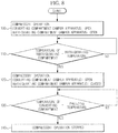
- FIG. 8 is a view illustrating a control method in a case that a converting compartment of a refrigerator is used for a freezing purpose in accordance with the embodiment of the present disclosure
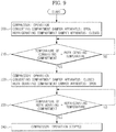
- FIG. 9 is a view illustrating a control method in a case that a converting compartment of a refrigerator is used for a refrigerating purpose in accordance with the embodiment of the present disclosure
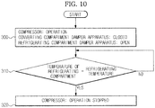
- FIG. 10 is a view illustrating a control method in a case that a converting compartment of a refrigerator is used for an off purpose in accordance with the embodiment of the present disclosure.
- FIGS. 1 to 10 a control method of the refrigerator in accordance with the embodiment of the present disclosure will be explained.
- the cooling of the converting compartment 13 and the refrigerating compartment 14 is started (100) by opening the converting compartment damper apparatus 80 and the refrigerating compartment damper apparatus 81, and by operating the compressor 41.
- the refrigerator 1 determines (110) whether the temperature of the refrigerating compartment 14 is at the refrigerating temperature, and when the temperature of the refrigerating compartment 14 is at the refrigerating temperature, the supply of the cold air flow to the refrigerating compartment 14 is shut off (120) by closing the refrigerating compartment damper apparatus 81.
- the refrigerator 1 determines whether the temperature of the converting compartment 13 is at the freezing temperature, and the cooling is stopped (140) by discontinuing the operation of the compressor 41 when the temperature of the converting compartment 13 is at the freezing temperature.
- the converting compartment 13 may be used for the freezing purpose, and the refrigerating compartment 14 may be used for the refrigerating purpose.
- the cooling of the converting compartment 13 and the refrigerating compartment 14 is started (200) by opening the converting compartment damper apparatus 80 and the refrigerating compartment damper apparatus 81, and by operating the compressor 41.
- the converting compartment 13 since the converting compartment 13 is provided with a larger and thicker insulation wall 25 than the refrigerating compartment 14, the converting compartment 13 reaches the refrigerating temperature before the refrigerating compartment 14.
- the refrigerator 1 first determines (210) whether the temperature of the converting compartment 13 is at the refrigerating temperature, and when the temperature of the converting compartment 13 is at the refrigerating temperature, the supply of the cold air flow to the converting compartment 13 is shut off (220) by closing the converting compartment damper apparatus 81.
- the refrigerator 1 determines (230) during the cooling process whether the temperature of the refrigerating compartment 14 is at the refrigerating temperature, and when the temperature of the refrigerating compartment 14 is at the refrigerating temperature, the operation of the compressor 41 is stopped (240).
- the converting compartment 13 and the refrigerating compartment 14 may be used for the refrigerating purpose.
- frost may form at the converting compartment discharging flow path 70 due to the temperature difference.
- the cold air flow is circulated to the converting compartment discharging flow path 70 by intermittently opening the converting compartment damper apparatus 80 even in a case that the temperature of the converting compartment 13 is already at the refrigerating temperature.
- the cooling of the refrigerating compartment 14 is started (300) by operating the compressor 41 in a state that the converting compartment damper apparatus 80 is closed and the refrigerating compartment damper apparatus 81 is open.
- the refrigerator 1 determines (310) during the cooling process whether the temperature of the refrigerating compartment 14 is at the refrigerating temperature, and when the temperature of the refrigerating compartment 14 is at the refrigerating temperature, the operation of the compressor 41 is stopped (320).
- the converting compartment 13 is turned off, and the refrigerating compartment 14 may only be used.
- frost is prevented from forming at the converting compartment discharging flow path 70, while the converting compartment damper apparatus 80 is closed and the compressor 41 continues to operate to cool the refrigerating compartment 14, by circulating the cold air flow to the converting compartment discharging flow path 70 by intermittently opening the converting compartment damper apparatus 80, as previously explained.
- the defrost heat is contained at the inside of the distributing flow path 60 in a state that the defrost heat is unable to spread outside.
- the refrigerant maintains at a state of a high pressure as the evaporator 14 is maintained at a high temperature, and thereby a defect due to an overload may occur when the compressor 41 is operated.
- the evaporator 14 is cooled by opening the refrigerating compartment damper apparatus 81 and operating the draft fan 42 prior to operating the compressor 41 again after or at the time of the defrost process.
- frost may form at the converting compartment discharging flow path 70 due to the temperature difference, and therefore, the refrigerating compartment damper apparatus 81 is opened.
Landscapes
- Engineering & Computer Science (AREA)
- Chemical & Material Sciences (AREA)
- Combustion & Propulsion (AREA)
- Physics & Mathematics (AREA)
- Mechanical Engineering (AREA)
- Thermal Sciences (AREA)
- General Engineering & Computer Science (AREA)
- Cold Air Circulating Systems And Constructional Details In Refrigerators (AREA)
- Devices That Are Associated With Refrigeration Equipment (AREA)
Claims (14)
- Kühlschrank, welcher aufweist:einen Körper (10);einen ersten Speicherraum (13) und einen zweiten Speicherraum (14), voneinander abgeteilt vorgesehen, in einem Inneren des Körpers;einen Kompressor (41), einen Kondensor und einen Verdampfer (40), ausgebildet zur Bildung eines Kühlzyklus;einen ersten Fließweg (70) und einen zweiten Fließweg (71), ausgebildet zur Führung eines Kaltluftstroms erzeugt durch den Verdampfer zum ersten Speicherraum und entsprechend zum zweiten Speicherraum;einen Gebläselüfter (42), ausgebildet zur Zirkulation des Kaltluftstroms erzeugt durch den Verdampfer;ein erstes Kaltluftstromsteuergerät (80) und ein zweites Kaltluftstromsteuergerät (81), installiert entsprechend am ersten Fließweg und am zweiten Fließweg und ausgebildet zur Steuerung der Zufuhr des Kaltluftstroms; undeinen ersten Temperatursensor und einen zweiten Temperatursensor, jeweils ausgebildet zur Messung der Temperatur des ersten Speicherraums und der Temperatur des zweiten Speicherraums, wobei ein Modus etabliert werden kann von einem ersten Modus, ausgebildet zur Verwendung des ersten Speicherraums und des zweiten Speicherraums jeweils zum Gefrieren und Kühlen, einem zweiten Modus, jeweils zum Kühlen in beiden Fällen, und einem dritten Modus zum Ausschalten und Kühlen,dadurch gekennzeichnet, dassim Falle des Verwendens des ersten Modus die Tätigkeit des Kompressors festgelegt wird basierend auf der Temperatur des ersten Speicherraums und im Falle des zweiten Modus oder dritten Modus, die Tätigkeit des Kompressors festgelegt wird basierend auf der Temperatur des zweiten Speicherraums.
- Kühlschrank nach Anspruch 1, wobei im Falle des ersten Modus, der Kompressor (41) betätigt wird, bis die Temperatur des ersten Speicherraums (13) eine Gefriertemperatur erreicht, und angehalten wird, wenn die Temperatur des ersten Speicherraums eine Gefriertemperatur erreicht.
- Kühlschrank nach Anspruch 1, wobei im Falle des zweiten Modus oder des dritten Modus, der Kompressor (41) betätigt wird, bis die Temperatur des zweiten Speicherraums (14) eine Kühltemperatur erreicht, und angehalten wird, wenn die Temperatur des zweiten Speicherraums eine Kühltemperatur erreicht hat.
- Kühlschrank nach Anspruch 1, wobei im Falle des ersten Modus das zweite Kaltluftstromsteuergerät (81) die Zufuhr des Kaltluftstroms zum zweiten Speicherraum (14) unterbricht, wenn die Temperatur des zweiten Speicherraums die Kühltemperatur erreicht hat.
- Kühlschrank nach Anspruch 1, wobei im Falle des zweiten Modus das erste Kaltluftstromsteuergerät (80) die Zufuhr des Kaltluftstroms zum ersten Speicherraum (13) unterbricht, wenn die Temperatur des ersten Speicherraums die Kühltemperatur erreicht hat.
- Kühlschrank nach Anspruch 1, wobei im Falle des dritten Modus das erste Kaltluftstromsteuergerät (80) die Zufuhr des Kaltluftstroms zum ersten Speicherraum (13) unterbricht.
- Kühlschrank nach Anspruch 1, wobei im Falle des zweiten Modus oder des dritten Modus der Kaltluftstrom intermittierend im ersten Strömungsweg (70) zirkuliert, um Reifbildung im ersten Strömungsweg zu verhindern.
- Kühlschrank nach Anspruch 1, wobei im Falle des zweiten Modus oder des dritten Modus ein Kaltluftstrom in wenigstens einem von entweder erstem Strömungsweg (70) oder zweitem Strömungsweg (41) zirkuliert, um die Wärme des Verdampfers (40) während oder nach einem Entfrosten des Verdampfers zu reduzieren.
- Kühlschrank nach Anspruch 1, wobei der Gebläselüfter (42) ein Radiallüfter ist.
- Kühlschrank nach Anspruch 1, welcher weiterhin aufweist:
eine Führungseinheit (30), ausgebildet zur Teilung des Abteils in einen Speicherraum (51) vorne und das Kaltluftstromerzeugungsabteil (50) hinten. - Kühlschrank nach Anspruch 10, wobei ein Verteilungsströmungsweg (60) im Inneren der Führungseinheit (30) gebildet ist, welcher ausgebildet ist zur Verteilung des durch das Kaltluftstromerzeugungsgerät erzeugten Kaltluftstroms zum ersten Strömungsweg (70) und zum zweiten Strömungsweg (71).
- Kühlschrank nach Anspruch 10, wobei der erste Strömungsweg (70) einen hinteren Strömungsweg (72) gebildet hinten in der Führungseinheit und einen Durchdringungsströmungsweg (73) aufweist, welcher den hinteren Strömungsweg und den Speicherraum nach Durchdringen der Führungseinheit (30) verbindet.
- Kühlschrank nach Anspruch 12, wobei das Kaltluftstromsteuergerät am hinteren Strömungsweg installiert ist.
- Kühlschank nach Anspruch 12, wobei der hintere Strömungsweg (72) auf einer Seite des Verdampfers (40) angeordnet ist.
Priority Applications (1)
| Application Number | Priority Date | Filing Date | Title |
|---|---|---|---|
| PL12180410T PL2559960T3 (pl) | 2011-08-16 | 2012-08-14 | Lodówka i sposób sterowania nią |
Applications Claiming Priority (1)
| Application Number | Priority Date | Filing Date | Title |
|---|---|---|---|
| KR1020110081383A KR101809971B1 (ko) | 2011-08-16 | 2011-08-16 | 냉장고 및 그 제어방법 |
Publications (3)
| Publication Number | Publication Date |
|---|---|
| EP2559960A2 EP2559960A2 (de) | 2013-02-20 |
| EP2559960A3 EP2559960A3 (de) | 2017-07-05 |
| EP2559960B1 true EP2559960B1 (de) | 2019-05-29 |
Family
ID=46679193
Family Applications (1)
| Application Number | Title | Priority Date | Filing Date |
|---|---|---|---|
| EP12180410.8A Not-in-force EP2559960B1 (de) | 2011-08-16 | 2012-08-14 | Kühlschrank und Steuerungsverfahren dafür |
Country Status (4)
| Country | Link |
|---|---|
| US (1) | US20130042641A1 (de) |
| EP (1) | EP2559960B1 (de) |
| KR (1) | KR101809971B1 (de) |
| PL (1) | PL2559960T3 (de) |
Families Citing this family (20)
| Publication number | Priority date | Publication date | Assignee | Title |
|---|---|---|---|---|
| EP2789937B1 (de) * | 2013-04-09 | 2019-03-27 | Whirlpool Corporation | Kühlschrank mit einem verwandelbaren Fach und Verfahren zum Einstellen der Temperatur darin |
| KR102176725B1 (ko) * | 2013-12-20 | 2020-11-10 | 삼성전자주식회사 | 냉장고 |
| KR102310657B1 (ko) * | 2015-03-20 | 2021-10-12 | 삼성전자주식회사 | 냉장고 |
| CN105758093B (zh) * | 2016-03-09 | 2018-04-20 | 青岛海尔股份有限公司 | 冰箱及用于冰箱的分路送风装置 |
| KR101852677B1 (ko) * | 2016-05-26 | 2018-04-26 | 엘지전자 주식회사 | 냉장고 |
| CN106247753B (zh) * | 2016-09-30 | 2019-05-03 | 青岛海尔股份有限公司 | 一种冰箱及该冰箱的控制方法 |
| DE102016220163A1 (de) * | 2016-10-14 | 2018-04-19 | BSH Hausgeräte GmbH | Kältegerät mit Dörrfunktion und Betriebsverfahren dafür |
| US10041717B2 (en) * | 2016-10-27 | 2018-08-07 | Electrolux Home Products, Inc. | Air tower improvement for a refrigerator |
| EP3538826B1 (de) * | 2016-12-15 | 2022-04-06 | Samsung Electronics Co., Ltd. | Kühlschrank |
| JP6803217B2 (ja) * | 2016-12-15 | 2020-12-23 | 三星電子株式会社Samsung Electronics Co.,Ltd. | 冷蔵庫 |
| JP6931763B2 (ja) * | 2017-03-08 | 2021-09-08 | パナソニックIpマネジメント株式会社 | 冷蔵庫 |
| KR102747193B1 (ko) * | 2018-11-30 | 2024-12-27 | 삼성전자주식회사 | 냉장고 및 그 제어방법 |
| JP7226770B2 (ja) * | 2018-12-20 | 2023-02-21 | アクア株式会社 | 遮蔽装置およびそれを備えた冷蔵庫 |
| EP3963272A4 (de) | 2019-06-07 | 2022-08-03 | Samsung Electronics Co., Ltd. | Gebläse und kühlschrank |
| KR102836644B1 (ko) * | 2019-08-02 | 2025-07-18 | 엘지전자 주식회사 | 냉장고 |
| KR20210099265A (ko) * | 2020-02-04 | 2021-08-12 | 삼성전자주식회사 | 냉장고 |
| CN112797702B (zh) * | 2020-12-30 | 2022-09-02 | 佛山市美之雪制冷设备有限公司 | 冰箱的控制方法 |
| KR20230020164A (ko) * | 2021-08-03 | 2023-02-10 | 엘지전자 주식회사 | 냉장고 및 그의 운전 제어방법 |
| KR20240022348A (ko) * | 2022-08-11 | 2024-02-20 | 삼성전자주식회사 | 냉장고 |
| US12305906B2 (en) * | 2022-12-14 | 2025-05-20 | Electrolux Consumer Products, Inc. | Air cooling assembly for a cooling device |
Family Cites Families (26)
| Publication number | Priority date | Publication date | Assignee | Title |
|---|---|---|---|---|
| US3261173A (en) * | 1964-07-29 | 1966-07-19 | Gen Motors Corp | Refrigerating apparatus |
| US3411312A (en) * | 1967-09-01 | 1968-11-19 | Whirlpool Co | Refrigerator with convertible compartment |
| US3499295A (en) * | 1968-06-17 | 1970-03-10 | Emhart Corp | Refrigeration system |
| IT1260457B (it) * | 1992-01-28 | 1996-04-09 | Whirlpool Italia | Refrigeratore combinato a circolazione forzata d'aria convertibile in refrigeratore con almeno due vani a temperatura sostanzialmente identica |
| EP0984235B1 (de) * | 1994-11-11 | 2002-12-18 | Samsung Electronics Co., Ltd. | Steuerungsverfahren für einen Kühlschrank mit Hochleistungsmehrverdampferkreislauf |
| JP2000046456A (ja) * | 1998-07-29 | 2000-02-18 | Sankyo Seiki Mfg Co Ltd | 冷蔵庫 |
| WO2002016843A1 (en) * | 2000-08-23 | 2002-02-28 | Bpl Refrigeration Limited | Frost free refrigerator having means to convert the freezer compartment also to fresh food compartment |
| JP4045139B2 (ja) * | 2002-07-24 | 2008-02-13 | Sriスポーツ株式会社 | マルチピースソリッドゴルフボール |
| US6931870B2 (en) * | 2002-12-04 | 2005-08-23 | Samsung Electronics Co., Ltd. | Time division multi-cycle type cooling apparatus and method for controlling the same |
| KR100505254B1 (ko) * | 2003-03-31 | 2005-08-03 | 엘지전자 주식회사 | 냉장고의 온도 제어 방법 |
| US7032407B2 (en) * | 2003-06-27 | 2006-04-25 | General Electric Company | Methods and apparatus for refrigerator compartment |
| US20060086126A1 (en) * | 2004-10-25 | 2006-04-27 | Maytag Corporation | Convertible refrigerator/freezer |
| EP1811251A2 (de) * | 2006-01-18 | 2007-07-25 | Samsung Electronics Co., Ltd. | Kühlschrank mit Temperaturregelung und Betriebsverfahren dafür |
| US20100016274A1 (en) * | 2006-09-14 | 2010-01-21 | Koppel Gary A | Beta-lactam cannabinoid receptor modulators |
| US20080156010A1 (en) * | 2007-01-02 | 2008-07-03 | Lg Electronics Inc. | Refrigerator |
| JP4916891B2 (ja) * | 2007-01-05 | 2012-04-18 | シャープ株式会社 | 冷蔵庫 |
| KR100850954B1 (ko) * | 2007-03-30 | 2008-08-08 | 엘지전자 주식회사 | 냉장고 및 그 제어방법 |
| KR20080088807A (ko) * | 2007-03-30 | 2008-10-06 | 엘지전자 주식회사 | 냉장고의 제상장치 |
| KR100873140B1 (ko) * | 2007-03-31 | 2008-12-09 | 엘지전자 주식회사 | 냉장고 |
| EP2144023A4 (de) * | 2007-04-26 | 2012-08-08 | Panasonic Corp | Kühlschrank |
| US7891205B2 (en) * | 2007-05-17 | 2011-02-22 | Electrolux Home Products, Inc. | Refrigerator defrosting and chilling compartment |
| KR101402628B1 (ko) * | 2007-06-11 | 2014-06-09 | 삼성전자 주식회사 | 냉장고 및 그 운전방법 |
| KR20090046251A (ko) * | 2007-11-05 | 2009-05-11 | 엘지전자 주식회사 | 냉장고 및 그 제어방법 |
| KR20090046298A (ko) * | 2007-11-05 | 2009-05-11 | 엘지전자 주식회사 | 음식물 보관기기 및 그 제어방법 |
| KR20100076089A (ko) * | 2008-12-26 | 2010-07-06 | 엘지전자 주식회사 | 냉장고 |
| US8074469B2 (en) * | 2008-12-31 | 2011-12-13 | General Electric Company | Refrigerator with a convertible compartment |
-
2011
- 2011-08-16 KR KR1020110081383A patent/KR101809971B1/ko not_active Expired - Fee Related
-
2012
- 2012-08-14 PL PL12180410T patent/PL2559960T3/pl unknown
- 2012-08-14 EP EP12180410.8A patent/EP2559960B1/de not_active Not-in-force
- 2012-08-15 US US13/585,915 patent/US20130042641A1/en not_active Abandoned
Non-Patent Citations (1)
| Title |
|---|
| None * |
Also Published As
| Publication number | Publication date |
|---|---|
| EP2559960A2 (de) | 2013-02-20 |
| EP2559960A3 (de) | 2017-07-05 |
| US20130042641A1 (en) | 2013-02-21 |
| KR20130019307A (ko) | 2013-02-26 |
| PL2559960T3 (pl) | 2019-12-31 |
| KR101809971B1 (ko) | 2017-12-18 |
Similar Documents
| Publication | Publication Date | Title |
|---|---|---|
| EP2559960B1 (de) | Kühlschrank und Steuerungsverfahren dafür | |
| EP3497387B1 (de) | Kühlschrank | |
| US9726417B2 (en) | Refrigerator | |
| US20140008044A1 (en) | Heat exchanger and method of manufacturing the same | |
| US20160138848A1 (en) | Refrigerator | |
| US10539357B2 (en) | Refrigerator and method of controlling the same | |
| EP3158275B1 (de) | Kühlschrank | |
| WO2009017286A1 (en) | Refrigerator with evaporator installed in ice-making room | |
| EP2778577B1 (de) | Kühlschrank | |
| WO2009017282A1 (en) | Refrigerator with refrigeration system of ice_making room installed in door | |
| KR20160091106A (ko) | 냉장고 | |
| CN109855351A (zh) | 冰箱及其控制方法 | |
| CN108362066A (zh) | 风机遮蔽装置及冰箱 | |
| US20210239382A1 (en) | Refrigerator | |
| CN102410690A (zh) | 冰箱 | |
| JP2013127345A (ja) | 冷蔵庫 | |
| KR20150145852A (ko) | 냉장고 및 그 제어방법 | |
| WO2009017283A1 (en) | Refrigerator with evaporator installed in door | |
| US20160370058A1 (en) | Refrigerator and refrigerant circulation apparatus and method for making ice | |
| JP2017040398A (ja) | 冷蔵庫 | |
| US20160370088A1 (en) | Refrigerator and ice making method therefor | |
| JPH11304332A (ja) | 冷蔵庫の制御方法 | |
| KR101651329B1 (ko) | 냉장고 및 그 제어방법 | |
| KR20150024504A (ko) | 압축기의 컨트롤박스 | |
| JP2024151095A (ja) | 冷蔵庫 |
Legal Events
| Date | Code | Title | Description |
|---|---|---|---|
| PUAI | Public reference made under article 153(3) epc to a published international application that has entered the european phase |
Free format text: ORIGINAL CODE: 0009012 |
|
| AK | Designated contracting states |
Kind code of ref document: A2 Designated state(s): AL AT BE BG CH CY CZ DE DK EE ES FI FR GB GR HR HU IE IS IT LI LT LU LV MC MK MT NL NO PL PT RO RS SE SI SK SM TR |
|
| AX | Request for extension of the european patent |
Extension state: BA ME |
|
| PUAL | Search report despatched |
Free format text: ORIGINAL CODE: 0009013 |
|
| AK | Designated contracting states |
Kind code of ref document: A3 Designated state(s): AL AT BE BG CH CY CZ DE DK EE ES FI FR GB GR HR HU IE IS IT LI LT LU LV MC MK MT NL NO PL PT RO RS SE SI SK SM TR |
|
| AX | Request for extension of the european patent |
Extension state: BA ME |
|
| RIC1 | Information provided on ipc code assigned before grant |
Ipc: F25D 17/06 20060101AFI20170601BHEP |
|
| STAA | Information on the status of an ep patent application or granted ep patent |
Free format text: STATUS: REQUEST FOR EXAMINATION WAS MADE |
|
| 17P | Request for examination filed |
Effective date: 20171123 |
|
| RBV | Designated contracting states (corrected) |
Designated state(s): AL AT BE BG CH CY CZ DE DK EE ES FI FR GB GR HR HU IE IS IT LI LT LU LV MC MK MT NL NO PL PT RO RS SE SI SK SM TR |
|
| GRAP | Despatch of communication of intention to grant a patent |
Free format text: ORIGINAL CODE: EPIDOSNIGR1 |
|
| STAA | Information on the status of an ep patent application or granted ep patent |
Free format text: STATUS: GRANT OF PATENT IS INTENDED |
|
| INTG | Intention to grant announced |
Effective date: 20181221 |
|
| GRAS | Grant fee paid |
Free format text: ORIGINAL CODE: EPIDOSNIGR3 |
|
| GRAA | (expected) grant |
Free format text: ORIGINAL CODE: 0009210 |
|
| STAA | Information on the status of an ep patent application or granted ep patent |
Free format text: STATUS: THE PATENT HAS BEEN GRANTED |
|
| AK | Designated contracting states |
Kind code of ref document: B1 Designated state(s): AL AT BE BG CH CY CZ DE DK EE ES FI FR GB GR HR HU IE IS IT LI LT LU LV MC MK MT NL NO PL PT RO RS SE SI SK SM TR |
|
| REG | Reference to a national code |
Ref country code: GB Ref legal event code: FG4D |
|
| REG | Reference to a national code |
Ref country code: CH Ref legal event code: EP |
|
| REG | Reference to a national code |
Ref country code: AT Ref legal event code: REF Ref document number: 1138506 Country of ref document: AT Kind code of ref document: T Effective date: 20190615 |
|
| REG | Reference to a national code |
Ref country code: DE Ref legal event code: R096 Ref document number: 602012060547 Country of ref document: DE |
|
| REG | Reference to a national code |
Ref country code: IE Ref legal event code: FG4D |
|
| REG | Reference to a national code |
Ref country code: NL Ref legal event code: MP Effective date: 20190529 |
|
| REG | Reference to a national code |
Ref country code: LT Ref legal event code: MG4D |
|
| PG25 | Lapsed in a contracting state [announced via postgrant information from national office to epo] |
Ref country code: AL Free format text: LAPSE BECAUSE OF FAILURE TO SUBMIT A TRANSLATION OF THE DESCRIPTION OR TO PAY THE FEE WITHIN THE PRESCRIBED TIME-LIMIT Effective date: 20190529 Ref country code: PT Free format text: LAPSE BECAUSE OF FAILURE TO SUBMIT A TRANSLATION OF THE DESCRIPTION OR TO PAY THE FEE WITHIN THE PRESCRIBED TIME-LIMIT Effective date: 20190930 Ref country code: ES Free format text: LAPSE BECAUSE OF FAILURE TO SUBMIT A TRANSLATION OF THE DESCRIPTION OR TO PAY THE FEE WITHIN THE PRESCRIBED TIME-LIMIT Effective date: 20190529 Ref country code: SE Free format text: LAPSE BECAUSE OF FAILURE TO SUBMIT A TRANSLATION OF THE DESCRIPTION OR TO PAY THE FEE WITHIN THE PRESCRIBED TIME-LIMIT Effective date: 20190529 Ref country code: HR Free format text: LAPSE BECAUSE OF FAILURE TO SUBMIT A TRANSLATION OF THE DESCRIPTION OR TO PAY THE FEE WITHIN THE PRESCRIBED TIME-LIMIT Effective date: 20190529 Ref country code: NO Free format text: LAPSE BECAUSE OF FAILURE TO SUBMIT A TRANSLATION OF THE DESCRIPTION OR TO PAY THE FEE WITHIN THE PRESCRIBED TIME-LIMIT Effective date: 20190829 Ref country code: FI Free format text: LAPSE BECAUSE OF FAILURE TO SUBMIT A TRANSLATION OF THE DESCRIPTION OR TO PAY THE FEE WITHIN THE PRESCRIBED TIME-LIMIT Effective date: 20190529 Ref country code: LT Free format text: LAPSE BECAUSE OF FAILURE TO SUBMIT A TRANSLATION OF THE DESCRIPTION OR TO PAY THE FEE WITHIN THE PRESCRIBED TIME-LIMIT Effective date: 20190529 |
|
| PG25 | Lapsed in a contracting state [announced via postgrant information from national office to epo] |
Ref country code: LV Free format text: LAPSE BECAUSE OF FAILURE TO SUBMIT A TRANSLATION OF THE DESCRIPTION OR TO PAY THE FEE WITHIN THE PRESCRIBED TIME-LIMIT Effective date: 20190529 Ref country code: GR Free format text: LAPSE BECAUSE OF FAILURE TO SUBMIT A TRANSLATION OF THE DESCRIPTION OR TO PAY THE FEE WITHIN THE PRESCRIBED TIME-LIMIT Effective date: 20190830 Ref country code: BG Free format text: LAPSE BECAUSE OF FAILURE TO SUBMIT A TRANSLATION OF THE DESCRIPTION OR TO PAY THE FEE WITHIN THE PRESCRIBED TIME-LIMIT Effective date: 20190829 Ref country code: RS Free format text: LAPSE BECAUSE OF FAILURE TO SUBMIT A TRANSLATION OF THE DESCRIPTION OR TO PAY THE FEE WITHIN THE PRESCRIBED TIME-LIMIT Effective date: 20190529 |
|
| REG | Reference to a national code |
Ref country code: AT Ref legal event code: MK05 Ref document number: 1138506 Country of ref document: AT Kind code of ref document: T Effective date: 20190529 |
|
| PG25 | Lapsed in a contracting state [announced via postgrant information from national office to epo] |
Ref country code: AT Free format text: LAPSE BECAUSE OF FAILURE TO SUBMIT A TRANSLATION OF THE DESCRIPTION OR TO PAY THE FEE WITHIN THE PRESCRIBED TIME-LIMIT Effective date: 20190529 Ref country code: DK Free format text: LAPSE BECAUSE OF FAILURE TO SUBMIT A TRANSLATION OF THE DESCRIPTION OR TO PAY THE FEE WITHIN THE PRESCRIBED TIME-LIMIT Effective date: 20190529 Ref country code: SK Free format text: LAPSE BECAUSE OF FAILURE TO SUBMIT A TRANSLATION OF THE DESCRIPTION OR TO PAY THE FEE WITHIN THE PRESCRIBED TIME-LIMIT Effective date: 20190529 Ref country code: EE Free format text: LAPSE BECAUSE OF FAILURE TO SUBMIT A TRANSLATION OF THE DESCRIPTION OR TO PAY THE FEE WITHIN THE PRESCRIBED TIME-LIMIT Effective date: 20190529 Ref country code: RO Free format text: LAPSE BECAUSE OF FAILURE TO SUBMIT A TRANSLATION OF THE DESCRIPTION OR TO PAY THE FEE WITHIN THE PRESCRIBED TIME-LIMIT Effective date: 20190529 Ref country code: NL Free format text: LAPSE BECAUSE OF FAILURE TO SUBMIT A TRANSLATION OF THE DESCRIPTION OR TO PAY THE FEE WITHIN THE PRESCRIBED TIME-LIMIT Effective date: 20190529 Ref country code: CZ Free format text: LAPSE BECAUSE OF FAILURE TO SUBMIT A TRANSLATION OF THE DESCRIPTION OR TO PAY THE FEE WITHIN THE PRESCRIBED TIME-LIMIT Effective date: 20190529 |
|
| PG25 | Lapsed in a contracting state [announced via postgrant information from national office to epo] |
Ref country code: SM Free format text: LAPSE BECAUSE OF FAILURE TO SUBMIT A TRANSLATION OF THE DESCRIPTION OR TO PAY THE FEE WITHIN THE PRESCRIBED TIME-LIMIT Effective date: 20190529 Ref country code: IT Free format text: LAPSE BECAUSE OF FAILURE TO SUBMIT A TRANSLATION OF THE DESCRIPTION OR TO PAY THE FEE WITHIN THE PRESCRIBED TIME-LIMIT Effective date: 20190529 |
|
| REG | Reference to a national code |
Ref country code: DE Ref legal event code: R097 Ref document number: 602012060547 Country of ref document: DE |
|
| PLBE | No opposition filed within time limit |
Free format text: ORIGINAL CODE: 0009261 |
|
| STAA | Information on the status of an ep patent application or granted ep patent |
Free format text: STATUS: NO OPPOSITION FILED WITHIN TIME LIMIT |
|
| 26N | No opposition filed |
Effective date: 20200303 |
|
| PG25 | Lapsed in a contracting state [announced via postgrant information from national office to epo] |
Ref country code: MC Free format text: LAPSE BECAUSE OF FAILURE TO SUBMIT A TRANSLATION OF THE DESCRIPTION OR TO PAY THE FEE WITHIN THE PRESCRIBED TIME-LIMIT Effective date: 20190529 Ref country code: CH Free format text: LAPSE BECAUSE OF NON-PAYMENT OF DUE FEES Effective date: 20190831 Ref country code: SI Free format text: LAPSE BECAUSE OF FAILURE TO SUBMIT A TRANSLATION OF THE DESCRIPTION OR TO PAY THE FEE WITHIN THE PRESCRIBED TIME-LIMIT Effective date: 20190529 Ref country code: LU Free format text: LAPSE BECAUSE OF NON-PAYMENT OF DUE FEES Effective date: 20190814 Ref country code: LI Free format text: LAPSE BECAUSE OF NON-PAYMENT OF DUE FEES Effective date: 20190831 |
|
| REG | Reference to a national code |
Ref country code: BE Ref legal event code: MM Effective date: 20190831 |
|
| PG25 | Lapsed in a contracting state [announced via postgrant information from national office to epo] |
Ref country code: IE Free format text: LAPSE BECAUSE OF NON-PAYMENT OF DUE FEES Effective date: 20190814 |
|
| PG25 | Lapsed in a contracting state [announced via postgrant information from national office to epo] |
Ref country code: BE Free format text: LAPSE BECAUSE OF NON-PAYMENT OF DUE FEES Effective date: 20190831 |
|
| PGFP | Annual fee paid to national office [announced via postgrant information from national office to epo] |
Ref country code: GB Payment date: 20200722 Year of fee payment: 9 Ref country code: FR Payment date: 20200722 Year of fee payment: 9 Ref country code: TR Payment date: 20200721 Year of fee payment: 9 |
|
| PGFP | Annual fee paid to national office [announced via postgrant information from national office to epo] |
Ref country code: PL Payment date: 20200727 Year of fee payment: 9 |
|
| PG25 | Lapsed in a contracting state [announced via postgrant information from national office to epo] |
Ref country code: CY Free format text: LAPSE BECAUSE OF FAILURE TO SUBMIT A TRANSLATION OF THE DESCRIPTION OR TO PAY THE FEE WITHIN THE PRESCRIBED TIME-LIMIT Effective date: 20190529 |
|
| PG25 | Lapsed in a contracting state [announced via postgrant information from national office to epo] |
Ref country code: IS Free format text: LAPSE BECAUSE OF FAILURE TO SUBMIT A TRANSLATION OF THE DESCRIPTION OR TO PAY THE FEE WITHIN THE PRESCRIBED TIME-LIMIT Effective date: 20190929 |
|
| PG25 | Lapsed in a contracting state [announced via postgrant information from national office to epo] |
Ref country code: HU Free format text: LAPSE BECAUSE OF FAILURE TO SUBMIT A TRANSLATION OF THE DESCRIPTION OR TO PAY THE FEE WITHIN THE PRESCRIBED TIME-LIMIT; INVALID AB INITIO Effective date: 20120814 Ref country code: MT Free format text: LAPSE BECAUSE OF FAILURE TO SUBMIT A TRANSLATION OF THE DESCRIPTION OR TO PAY THE FEE WITHIN THE PRESCRIBED TIME-LIMIT Effective date: 20190529 |
|
| PGFP | Annual fee paid to national office [announced via postgrant information from national office to epo] |
Ref country code: DE Payment date: 20210720 Year of fee payment: 10 |
|
| GBPC | Gb: european patent ceased through non-payment of renewal fee |
Effective date: 20210814 |
|
| PG25 | Lapsed in a contracting state [announced via postgrant information from national office to epo] |
Ref country code: MK Free format text: LAPSE BECAUSE OF FAILURE TO SUBMIT A TRANSLATION OF THE DESCRIPTION OR TO PAY THE FEE WITHIN THE PRESCRIBED TIME-LIMIT Effective date: 20190529 |
|
| PG25 | Lapsed in a contracting state [announced via postgrant information from national office to epo] |
Ref country code: GB Free format text: LAPSE BECAUSE OF NON-PAYMENT OF DUE FEES Effective date: 20210814 Ref country code: FR Free format text: LAPSE BECAUSE OF NON-PAYMENT OF DUE FEES Effective date: 20210831 |
|
| REG | Reference to a national code |
Ref country code: DE Ref legal event code: R119 Ref document number: 602012060547 Country of ref document: DE |
|
| PG25 | Lapsed in a contracting state [announced via postgrant information from national office to epo] |
Ref country code: DE Free format text: LAPSE BECAUSE OF NON-PAYMENT OF DUE FEES Effective date: 20230301 |
|
| PG25 | Lapsed in a contracting state [announced via postgrant information from national office to epo] |
Ref country code: PL Free format text: LAPSE BECAUSE OF NON-PAYMENT OF DUE FEES Effective date: 20210814 |
|
| PG25 | Lapsed in a contracting state [announced via postgrant information from national office to epo] |
Ref country code: TR Free format text: LAPSE BECAUSE OF NON-PAYMENT OF DUE FEES Effective date: 20210814 |