EP2559982B1 - Système et méthode de mesure de la résistance de trois résistances sensibles à la température - Google Patents
Système et méthode de mesure de la résistance de trois résistances sensibles à la température Download PDFInfo
- Publication number
- EP2559982B1 EP2559982B1 EP12174891.7A EP12174891A EP2559982B1 EP 2559982 B1 EP2559982 B1 EP 2559982B1 EP 12174891 A EP12174891 A EP 12174891A EP 2559982 B1 EP2559982 B1 EP 2559982B1
- Authority
- EP
- European Patent Office
- Prior art keywords
- terminal
- resistors
- measuring
- electronic
- switches
- Prior art date
- Legal status (The legal status is an assumption and is not a legal conclusion. Google has not performed a legal analysis and makes no representation as to the accuracy of the status listed.)
- Active
Links
Images

Classifications
-
- G—PHYSICS
- G01—MEASURING; TESTING
- G01K—MEASURING TEMPERATURE; MEASURING QUANTITY OF HEAT; THERMALLY-SENSITIVE ELEMENTS NOT OTHERWISE PROVIDED FOR
- G01K7/00—Measuring temperature based on the use of electric or magnetic elements directly sensitive to heat ; Power supply therefor, e.g. using thermoelectric elements
- G01K7/16—Measuring temperature based on the use of electric or magnetic elements directly sensitive to heat ; Power supply therefor, e.g. using thermoelectric elements using resistive elements
-
- G—PHYSICS
- G01—MEASURING; TESTING
- G01K—MEASURING TEMPERATURE; MEASURING QUANTITY OF HEAT; THERMALLY-SENSITIVE ELEMENTS NOT OTHERWISE PROVIDED FOR
- G01K1/00—Details of thermometers not specially adapted for particular types of thermometer
- G01K1/02—Means for indicating or recording specially adapted for thermometers
- G01K1/026—Means for indicating or recording specially adapted for thermometers arrangements for monitoring a plurality of temperatures, e.g. by multiplexing
-
- G—PHYSICS
- G01—MEASURING; TESTING
- G01K—MEASURING TEMPERATURE; MEASURING QUANTITY OF HEAT; THERMALLY-SENSITIVE ELEMENTS NOT OTHERWISE PROVIDED FOR
- G01K2207/00—Application of thermometers in household appliances
- G01K2207/02—Application of thermometers in household appliances for measuring food temperature
- G01K2207/06—Application of thermometers in household appliances for measuring food temperature for preparation purposes
Definitions
- the invention relates to a system comprising a multi-core temperature sensor with a circuit for measuring three temperature-dependent resistors according to claim 1 and a method for determining resistance of three temperature-dependent resistors according to claim 6.
- core temperature sensor with a temperature resistance so-called single-point core temperature sensor known.
- the resistance used here is temperature-dependent.
- a thermistor also referred to as NTC resistor
- PTC resistor also referred to as PTC resistor
- the temperature of the sensor or of the measuring point at the location of the sensor can be determined from the resistance value of the thermistor or the PTC thermistor.
- the single-point core temperature probe requires a two-pole connection to a measuring electronics to measure the temperature value.
- Fig.1 shows a known circuit arrangement with a measuring electronics 101 and a three-point core temperature sensor 102 which is temporarily connected via one of three terminals with the measuring electronics 101.
- the three-point core temperature sensor 102 has three temperature-dependent resistors 103, 104 and 105, which are connected on one side to ground potential 106 and each have a terminal 107, 108 and 109 on the other side.
- a four-pin connector (comprising the terminals 107 to 109 and ground potential) is required to evaluate the three resistors 103 to 105.
- each of the resistors 103 to 105 is connected to a measuring unit 111 via a switch 110 and the respectively connected resistance between ground potential 106 and the contacted terminal measured.
- This circuit requires for a three-point core temperature sensor 102, a four-pin connector to the measuring electronics 101st
- DE 693 0 966 T2 discloses an oven for treating food, comprising a temperature meter for insertion into a food to be heated, the temperature meter having the shape of a rod and carrying at its tip and along at least one further position a temperature sensor and the temperature meter with a control device for controlling the Treatment process is connectable in the oven, wherein together at least three temperature sensors provided on the temperature meter and suitably spaced from each other, the control device is designed so that the control of the treatment process at the lowest temperature, which is determined by the sensors based.
- three sensors which are connected to each other in a star shape, wherein the three connection points formed by the free ends of the sensors are connected to their respective contact areas on a terminal which has a standardized shape in the manner of a telephone plug. It is also possible to provide three sensors which are connected to one another in a triangular manner, wherein the three connection points are connected to the respective contact region on a connection and the control device is designed such that it can transform the triangular connection into a star connection by means of known conversion formulas to determine the resistance values of the individual sensors.
- DE 10 2009 058 387 A1 discloses a method and apparatus for determining line resistances in three-wire circuit with resistance thermometers. To this end, the measuring resistor is short-circuited with short-circuiting bridges and the resistors are cyclically measured at the end of the cable. A system of equations can be used to calculate the actual line resistance and eliminate measurement errors.
- the object of the invention is to avoid the above-mentioned disadvantage and in particular to provide an efficient way of contacting a multipoint temperature sensor.
- the electronic switches can be activatable and deactivatable by the measuring electronics switch or switching functions.
- transistors or relays can be provided, which are controlled by means of the measuring electronics.
- the measuring electronics may have a processor or other processing unit which controls the electronic switches and determines the measured values, e.g. receives.
- the measuring electronics can perform different measurements based on the different positions of the electronic switches at different times, with a particular arrangement of the resistors resulting from the position of the electronic switch. Various arrangements result in the different measurements that are used to solve a system of equations with the resistance values of the three resistors.
- the measuring electronics may be a processing unit, in particular a processor unit and / or an at least partially hardwired or logic circuit arrangement.
- the measuring electronics can be or include any type of processor or computer or computer with correspondingly necessary peripherals (memory, input / output interfaces, input / output devices, etc.).
- the contacting or different wiring of the three resistors can be determined from the connections e.g. with a three-pin plug and a three-pin socket.
- the three resistors are temperature-dependent resistors, in particular thermistors or PTC thermistors.
- the domestic appliance can be a cooking appliance or an oven, with a possibility of contacting the multi-core temperature sensor mentioned here, wherein the contacting possibility comprises a three-pole socket or a three-pin plug.
- a further development consists in determining associated temperature values for the resistance values determined.
- a cooking appliance is controlled based on the temperature values.
- the method can be implemented, for example, in an electronics or control unit of the cooking appliance.
- the solution presented herein further includes a computer program product directly loadable into a memory of a digital computer comprising program code portions adapted to perform steps of the method described herein.
- a computer-readable storage medium eg of any memory, comprising computer-executable instructions (eg in the form of program code) suitable for the computer to perform steps of the method described herein.
- the three-point temperature sensor of the following example comprises three resistors A, B and C, which are connected differently.
- the resistors A, B and C may be arranged in a triangular circuit or in a star connection.
- bridges are provided by means of which three measurements can be carried out. From the individual measurements it is possible to deduce the (in particular temperature-dependent) values of the resistors A, B and C, e.g. by means of a processing unit (e.g., a processor) of a hearth electronics.
- a processing unit e.g., a processor
- circuit variants are shown by way of example.
- a particular circuit variant may be selected depending on how many (electronic) switches (e.g., transistors, relays, controllable outputs of a controller or processor) are needed and / or how the accuracy of the measurement behaves.
- switches e.g., transistors, relays, controllable outputs of a controller or processor
- the circuit makes it possible to measure as accurately as possible the measurement point with the lowest temperature, that is to say the temperature-dependent resistor which measures the lowest temperature value. This means low resistance when using PTC resistors and high resistance when using NTC resistors.
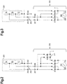
- Fig.2 shows an exemplary circuit arrangement of a core temperature sensor 201 with three measuring points.
- a connected to ground potential terminal 202 is again connected to itself via a series connection of the resistors C, B and A.
- a terminal 203 is connected to a node between the resistors C and B, and a terminal 204 is connected to a node between the resistors B and A.
- the terminals 202 to 204 are connected via a three-pole socket-plug connection with a measuring electronics 205, which has a plurality of switches S1 to S6 and a measuring unit 206 (with a terminal 209 and a terminal 210).
- the measuring electronics also has three connections, one of which is connected to ground potential (not in Fig.2 shown).
- a terminal 207 is connectable to the terminal 204 and a terminal 208 is connectable to the terminal 203.
- the terminal 207 is connected via the switch S1 to the terminal 209 and via the switch S6 to a node 211, wherein the node 211 is at ground potential.
- the terminal 208 is connected to the terminal 209 via the switch S2, to the terminal 210 via the switch S3 and to the terminal 211 via the switch S5. Furthermore, the node 211 is connected to the terminal 210 via the switch S4.
- the resistors A, B and C are arranged to give a triangular circuit.
- the three lines of the triangular circuit are connected to the terminals 202 to 204, the line connected to the terminal 202 is grounded (ground point).
- the measuring unit 206 can be connected to the core temperature sensor 201 via the electronic switches S1 to S6.
- the switches S1 to S6 are used e.g. via a processing unit (for example, a microcontroller or a processor) connected so that in each case a parallel circuit of a single resistor with a further single resistor or with the series connection of two individual resistors is connected to the measuring unit 206.
- a processing unit for example, a microcontroller or a processor
- the resistor R12 corresponds to the resistance between the terminals 202 and 203 when the terminal 204 is at ground potential.
- Resistor R13 corresponds to the resistance between terminals 202 and 204 when terminal 203 is at ground potential.
- Resistor R23 corresponds to the resistance between terminals 203 and 204 when terminal 202 is at ground potential.
- Equations (1) to (3) represent a system of equations with three unknowns (A, B and C) and three known quantities (R12, R13 and R23).
- the square root of equation (4) may be e.g. be performed by a digital microprocessor very easily by means of a known, fast converging iteration.
- this variant is advantageous when PTC resistors are used as temperature-dependent resistors A, B and C. Because then the smallest resistance value can be measured with the greatest accuracy in the parallel connection.
- Figure 3 shows an alternative variant of the circuit according to Fig.2 in which four switches S1 to S4 instead of the in Fig.2 six switches are provided shown.
- the core temperature sensor 201 has the same structure as well as the same terminals 202 to 204 in FIG Fig.2 ,
- the terminals 202 to 204 are connected via a three-pole socket-plug connection with the measuring electronics 205, which now has the switches S1 to S4 and the measuring unit 206 (with the terminal 209 and the terminal 210).
- the terminal 207 is connectable to the terminal 204 and the terminal 208 is connectable to the terminal 203.
- the terminal 207 is connected to the terminal 209 via the switch S1 and to the terminal 210 via the switch S4.
- the terminal 208 is connected to the terminal 209 via the switch S2 and to the terminal 210 via the switch S3.
- the terminal 210 is further connected to ground potential.
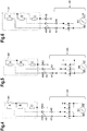
- Figure 4 shows another exemplary circuit arrangement of a core temperature sensor 401 with three measuring points.
- a connection 402 connected to ground potential is connected to a node 411 via a resistor C
- a connection 403 is connected to the node 411 via a resistor B
- a connection 404 is connected to the node 411 via a resistor A.
- the terminals 402 to 404 are connected via a three-pole socket-plug connection with a measuring electronics 405, which has a plurality of switches S1 to S4 and a measuring unit 406 (with a terminal 409 and a terminal 410).
- the measuring electronics also has three connections, one of which with ground potential is connected (not in Figure 4 shown).
- a port 407 is connectable to the port 404 and a port 408 is connectable to the port 403.
- the terminal 407 is connected to the terminal 409 via the switch S1.
- the terminal 408 is connected to the terminal 409 via the switch S2 and to the terminal 410 via the switch S3. Furthermore, the terminal 410 is connected to the ground potential via the switch S4.
- the three resistors A, B and C can be arranged in a star circuit with non-contacted star point.
- This circuit variant requires only four switches S1 to S4.
- This circuit example is advantageous when NTC resistors are used as temperature-dependent resistors A, B and C, because the individual measurements capture the series connection of the individual resistors according to Equations (13) to (15). Thus, the smallest temperature can be determined with great accuracy. As with the NTC resistor a low temperature means a large resistance value, the largest resistance can be determined in the series circuit with the greatest accuracy.
- FIG 5 shows an inventive alternative variant of the circuit according to Figure 4 in which three switches S1 to S3 instead of the in Figure 4 four switches are provided shown.
- the core temperature sensor 401 has the same structure as well as the same terminals 402 to 404 in FIG Figure 4 ,
- the terminals 402 to 404 are connected via a three-pole socket-plug connection with the measuring electronics 405, which now has the switches S1 to S3 and the measuring unit 406 (with the terminal 409 and the terminal 410).
- the terminal 407 is connectable to the terminal 404 and the terminal 408 is connectable to the terminal 403.
- the terminal 407 is connected to the terminal 409 via the switch S1.
- the terminal 408 is connected to the terminal 409 via the switch S2 and to the terminal 410 via the switch S3.
- the terminal 410 is further connected to ground potential.
- the lowest temperatures of three NTC resistors can advantageously be determined. It is also advantageous that the measuring device 406 can measure floating, i. one pole of the meter 406 performs a measurement with respect to ground potential.
- FIG 6 shows an inventive alternative variant of the circuit according to Figure 4 in which two switches S1 and S2 instead of the in Figure 4 four switches are provided shown.
- the core temperature sensor 401 has the same structure as well as the same terminals 402 to 404 in FIG Figure 4 ,
- the terminals 402 to 404 are connected via a three-pole socket-plug connection with the measuring electronics 405, which now has the switches S1 and S2 and the measuring unit 406 (with the terminal 409 and the terminal 410).
- the terminal 407 is connectable to the terminal 404 and the terminal 408 is connectable to the terminal 403.
- the terminal 407 is connected to the terminal 409 via the switch S1.
- the terminal 408 is connected to the terminal 409 via the switch S2.
- the terminal 410 is further connected to ground potential.
Landscapes
- Physics & Mathematics (AREA)
- General Physics & Mathematics (AREA)
- Measuring Temperature Or Quantity Of Heat (AREA)
- Measurement Of Resistance Or Impedance (AREA)
Claims (8)
- Système présentant- une sonde de température multi-coeur avec un montage (401) pour la mesure de trois résistances (A, B, C) dépendant de la température et- un appareil électroménager présentant une électronique de mesure (405) ainsi qu'une possibilité de mise en contact sous forme d'une prise femelle tripolaire ou d'une fiche tripolaire pour la sonde de température multi-coeur (401),- les trois résistances (A, B, C) pouvant être mises en contact par trois connexions (402-404) avec l'électronique de mesure (405),- les trois résistances (A, B, C) étant agencées en forme de montage en étoile (401),dans lequel une broche de chacune des trois résistances (A, B, C) est raccordée avec un noeud en étoile et l'autre broche respective de chacune des trois résistances (A, B, C) l'est avec l'une des trois connexions (402-404),
caractérisé en ce que- au moyen d'un commutateur électronique (S1-S2 ou S1-S3) de l'électronique de mesure (405), les trois résistances (A, B, C) peuvent être raccordées par leurs connexions (402-404),- à l'aide de différentes mesures à différents moments au moyen de l'électronique de mesure (405) les valeurs de résistance des résistances (A, B, C) peuvent être définies,- l'une des connexions (402) est raccordée au potentiel de masse et- au moyen de l'électronique de mesure (405) les connexions peuvent être raccordées par deux commutateurs électroniques (S1, S2) de telle sorte que les valeurs de résistance de mesure R12, R23 et R13 pour les trois résistances A, B et C peuvent être déterminées de la manière suivante:

 - sur base des valeurs de résistance de mesure R12, R23 et R123, les trois valeurs de résistance A, B et C peuvent être déterminées de la manière suivante:
 - ou au moyen de l'électronique de mesure, les connexions peuvent être raccordées par trois de telle sorte que
les valeurs de résistance de mesure R12, R23 et R123, peuvent être déterminées de la manière suivante:

 - sur base des valeurs de résistance de mesure R12, R23 et R123, les trois valeurs de résistance A, B et C peuvent être déterminées de la manière suivante:


- Système selon la revendication 1, dans lequel les trois résistances dépendant de la température sont des conducteurs à chaud ou des conducteurs à froid.
- Système selon l'une des revendications précédentes, dans lequel l'électronique de mesure présente trois commutateurs électroniques (S1-S3) et- une première connexion (407) de l'électronique de mesure (405) est raccordée par un premier commutateur (S1) à la première connexion (409) d'un élément de mesure (406),- une deuxième connexion (408) de l'électronique de mesure (405) est raccordée par un deuxième commutateur (S2) à la première connexion (409) de l'élément de mesure (406),- la deuxième connexion (408) de l'électronique de mesure (405) est raccordée par un troisième commutateur (S3) à la deuxième connexion (409) de l'élément de mesure (406) et la deuxième connexion (409) de l'élément de mesure (406) l'est à la masse.
- Système selon l'une des revendications 1 ou 2, dans lequel l'électronique de mesure présente deux commutateurs électroniques (S1-S2) et- une première connexion (407) de l'électronique de mesure (405) est raccordée par un premier commutateur (S1) à la première connexion (409) d'un élément de mesure (406),- une deuxième connexion (408) de l'électronique de mesure (405) est raccordée par un deuxième commutateur (S2) à la première connexion (409) de l'élément de mesure (406),- la deuxième connexion (409) de l'élément de mesure (406) est raccordée à la masse.
- Système selon l'une des revendications précédentes dans lequel l'appareil électroménager est un appareil de cuisson ou un four.
- Procédé de détermination de résistance de trois résistances dépendant de la température agencée en montage en étoile et qui font partie d'une sonde de température à coeur d'un système selon l'une des revendications précédentes,- dans lequel les trois résistances sont mises en contact électronique par trois connexions au moyen de commutateurs électroniques de l'électronique de mesure et- dans lequel à l'aide de différentes mesures à différents moments les valeurs de résistance des trois résistances sont déterminées.
- Procédé selon la revendication 6, dans lequel pour les valeurs de résistance déterminées, on définit des valeurs de température associées.
- Procédé selon la revendication 7, dans lequel un appareil de cuisson est commandé à l'aide des valeurs de température.
Priority Applications (1)
| Application Number | Priority Date | Filing Date | Title |
|---|---|---|---|
| PL12174891T PL2559982T3 (pl) | 2011-07-15 | 2012-07-04 | System i sposób oznaczania rezystancji trzech oporników zależnych od temperatury |
Applications Claiming Priority (1)
| Application Number | Priority Date | Filing Date | Title |
|---|---|---|---|
| DE201110079217 DE102011079217A1 (de) | 2011-07-15 | 2011-07-15 | Widerstandsmessung, insbesondere Temperaturbestimmung anhand temperaturabhängiger Widerstände |
Publications (3)
| Publication Number | Publication Date |
|---|---|
| EP2559982A2 EP2559982A2 (fr) | 2013-02-20 |
| EP2559982A3 EP2559982A3 (fr) | 2015-04-29 |
| EP2559982B1 true EP2559982B1 (fr) | 2018-05-09 |
Family
ID=46465107
Family Applications (1)
| Application Number | Title | Priority Date | Filing Date |
|---|---|---|---|
| EP12174891.7A Active EP2559982B1 (fr) | 2011-07-15 | 2012-07-04 | Système et méthode de mesure de la résistance de trois résistances sensibles à la température |
Country Status (5)
| Country | Link |
|---|---|
| EP (1) | EP2559982B1 (fr) |
| DE (1) | DE102011079217A1 (fr) |
| ES (1) | ES2672233T3 (fr) |
| PL (1) | PL2559982T3 (fr) |
| TR (1) | TR201808465T4 (fr) |
Families Citing this family (1)
| Publication number | Priority date | Publication date | Assignee | Title |
|---|---|---|---|---|
| DE102017206407B3 (de) | 2017-04-13 | 2018-07-05 | E.G.O. Elektro-Gerätebau GmbH | Schaltung und Verfahren zur Temperaturmessung und Temperaturfühler |
Family Cites Families (3)
| Publication number | Priority date | Publication date | Assignee | Title |
|---|---|---|---|---|
| DE3119496A1 (de) * | 1981-05-15 | 1982-12-23 | Bosch-Siemens Hausgeräte GmbH, 7000 Stuttgart | Speisenthermometer, insbesondere fuer mikrowellenherde |
| SE469857B (sv) * | 1992-02-07 | 1993-09-27 | Electrolux Ab | Temperaturprob avsedd att införas i en matvara som skall värmebehandlas jämte en ugn för behandling av matvaror innefattande en temperaturprob |
| DE102009058387A1 (de) * | 2009-12-15 | 2011-06-16 | Abb Ag | Verfahren und Vorrichtung zur Messung von Leitungswiderständen |
-
2011
- 2011-07-15 DE DE201110079217 patent/DE102011079217A1/de not_active Withdrawn
-
2012
- 2012-07-04 TR TR2018/08465T patent/TR201808465T4/tr unknown
- 2012-07-04 PL PL12174891T patent/PL2559982T3/pl unknown
- 2012-07-04 EP EP12174891.7A patent/EP2559982B1/fr active Active
- 2012-07-04 ES ES12174891.7T patent/ES2672233T3/es active Active
Non-Patent Citations (1)
| Title |
|---|
| None * |
Also Published As
| Publication number | Publication date |
|---|---|
| TR201808465T4 (tr) | 2018-07-23 |
| EP2559982A3 (fr) | 2015-04-29 |
| PL2559982T3 (pl) | 2019-05-31 |
| EP2559982A2 (fr) | 2013-02-20 |
| ES2672233T3 (es) | 2018-06-13 |
| DE102011079217A1 (de) | 2013-01-17 |
Similar Documents
| Publication | Publication Date | Title |
|---|---|---|
| EP2981833B1 (fr) | Résistance de mesure et procédé de mesure correspondant | |
| DE3818722C2 (fr) | ||
| DE102016202500A1 (de) | Batteriesensor, Verfahren zum Kalibrieren eines Messwiderstands und Verwendung | |
| DE102008041518A1 (de) | Akkumulatorüberwachungssystem | |
| EP2656034B1 (fr) | Thermomètre pour sonder une température centrale | |
| EP2675638A1 (fr) | Circuit destiné au chauffage électrique d'un siège | |
| EP2559981B1 (fr) | Mesure de résistance, notamment détermination de la température à l'aide de résistances sensibles à la température | |
| EP2559982B1 (fr) | Système et méthode de mesure de la résistance de trois résistances sensibles à la température | |
| DE102009058387A1 (de) | Verfahren und Vorrichtung zur Messung von Leitungswiderständen | |
| DE3634052C2 (fr) | ||
| DE102012220738A1 (de) | Messschaltung zum Bestimmen eines Widerstandswerts eines Sensorwider-standsbauelements | |
| DE102019200062A1 (de) | Batteriesensor und Verfahren zum Betrieb eines Batteriesensors | |
| DE102016202501A1 (de) | Verfahren zum Bestimmen eines Kalibrierstrompulses | |
| DE102008043326B4 (de) | Verfahren und Vorrichtung zur Widerstandsmessung eines von einer chemischen und/oder physikalischen Messgröße abhängigen Widerstandselements | |
| WO2006136496A1 (fr) | Determiner et/ou controler la temperature | |
| WO2009112412A1 (fr) | Dispositif de mesure d'une intensité de courant, dispositif de communication ainsi que procédé de mesure d'une intensité de courant | |
| DE112019004815T5 (de) | Technik des fraktionalen spiegelverhältnisses für digitale ferntemperatursensoren und zugehörige systeme, verfahren und vorrichtungen | |
| EP1879005B1 (fr) | Procédé destiné à la vérification d'un capteur de température doté d'au moins deux résistances sensibles à la température | |
| EP3489696A1 (fr) | Dispositif de mesure de courant, gamme de dispositifs de mesure de courant et procédé de mesure de courant | |
| EP2639511A2 (fr) | Procédé destiné au fonctionnement dýun appareil de cuisson avec thermomètre à rôti pouvant être connecté et appareil de cuisson | |
| DE10135173A1 (de) | Messvorrichtung, insbesondere für eine Heiz-/Klimaanlage | |
| DE1538302A1 (de) | Temperaturkompensiertes Pruefgeraet fuer Spannungskonstanthalter | |
| DE69201904T2 (de) | Vorrichtung zur Steuerung eines Kreuzspuleninstrumentes. | |
| WO2010149318A1 (fr) | Unité d'entrée/sortie | |
| DE2248157A1 (de) | Vorrichtung zum pruefen von vieladrigen leitungsverbindungen |
Legal Events
| Date | Code | Title | Description |
|---|---|---|---|
| PUAI | Public reference made under article 153(3) epc to a published international application that has entered the european phase |
Free format text: ORIGINAL CODE: 0009012 |
|
| AK | Designated contracting states |
Kind code of ref document: A2 Designated state(s): AL AT BE BG CH CY CZ DE DK EE ES FI FR GB GR HR HU IE IS IT LI LT LU LV MC MK MT NL NO PL PT RO RS SE SI SK SM TR |
|
| AX | Request for extension of the european patent |
Extension state: BA ME |
|
| RIN1 | Information on inventor provided before grant (corrected) |
Inventor name: HOFMANN, JOHANN Inventor name: BAUER, HANS-JUERGEN Inventor name: LAPPAT, HANS |
|
| RAP1 | Party data changed (applicant data changed or rights of an application transferred) |
Owner name: BSH HAUSGERAETE GMBH |
|
| PUAL | Search report despatched |
Free format text: ORIGINAL CODE: 0009013 |
|
| AK | Designated contracting states |
Kind code of ref document: A3 Designated state(s): AL AT BE BG CH CY CZ DE DK EE ES FI FR GB GR HR HU IE IS IT LI LT LU LV MC MK MT NL NO PL PT RO RS SE SI SK SM TR |
|
| AX | Request for extension of the european patent |
Extension state: BA ME |
|
| RIC1 | Information provided on ipc code assigned before grant |
Ipc: G01R 27/08 20060101ALI20150326BHEP Ipc: G01R 27/14 20060101ALI20150326BHEP Ipc: G01K 1/02 20060101AFI20150326BHEP Ipc: G01K 7/16 20060101ALI20150326BHEP Ipc: G01R 27/02 20060101ALI20150326BHEP |
|
| 17P | Request for examination filed |
Effective date: 20151029 |
|
| RBV | Designated contracting states (corrected) |
Designated state(s): AL AT BE BG CH CY CZ DE DK EE ES FI FR GB GR HR HU IE IS IT LI LT LU LV MC MK MT NL NO PL PT RO RS SE SI SK SM TR |
|
| 17Q | First examination report despatched |
Effective date: 20170707 |
|
| GRAP | Despatch of communication of intention to grant a patent |
Free format text: ORIGINAL CODE: EPIDOSNIGR1 |
|
| INTG | Intention to grant announced |
Effective date: 20171219 |
|
| GRAS | Grant fee paid |
Free format text: ORIGINAL CODE: EPIDOSNIGR3 |
|
| GRAA | (expected) grant |
Free format text: ORIGINAL CODE: 0009210 |
|
| AK | Designated contracting states |
Kind code of ref document: B1 Designated state(s): AL AT BE BG CH CY CZ DE DK EE ES FI FR GB GR HR HU IE IS IT LI LT LU LV MC MK MT NL NO PL PT RO RS SE SI SK SM TR |
|
| REG | Reference to a national code |
Ref country code: GB Ref legal event code: FG4D Free format text: NOT ENGLISH |
|
| REG | Reference to a national code |
Ref country code: CH Ref legal event code: EP Ref country code: AT Ref legal event code: REF Ref document number: 998008 Country of ref document: AT Kind code of ref document: T Effective date: 20180515 |
|
| REG | Reference to a national code |
Ref country code: IE Ref legal event code: FG4D Free format text: LANGUAGE OF EP DOCUMENT: GERMAN |
|
| REG | Reference to a national code |
Ref country code: DE Ref legal event code: R096 Ref document number: 502012012652 Country of ref document: DE |
|
| REG | Reference to a national code |
Ref country code: ES Ref legal event code: FG2A Ref document number: 2672233 Country of ref document: ES Kind code of ref document: T3 Effective date: 20180613 |
|
| REG | Reference to a national code |
Ref country code: FR Ref legal event code: PLFP Year of fee payment: 7 |
|
| REG | Reference to a national code |
Ref country code: NL Ref legal event code: MP Effective date: 20180509 |
|
| REG | Reference to a national code |
Ref country code: LT Ref legal event code: MG4D |
|
| PG25 | Lapsed in a contracting state [announced via postgrant information from national office to epo] |
Ref country code: LT Free format text: LAPSE BECAUSE OF FAILURE TO SUBMIT A TRANSLATION OF THE DESCRIPTION OR TO PAY THE FEE WITHIN THE PRESCRIBED TIME-LIMIT Effective date: 20180509 Ref country code: BG Free format text: LAPSE BECAUSE OF FAILURE TO SUBMIT A TRANSLATION OF THE DESCRIPTION OR TO PAY THE FEE WITHIN THE PRESCRIBED TIME-LIMIT Effective date: 20180809 Ref country code: SE Free format text: LAPSE BECAUSE OF FAILURE TO SUBMIT A TRANSLATION OF THE DESCRIPTION OR TO PAY THE FEE WITHIN THE PRESCRIBED TIME-LIMIT Effective date: 20180509 Ref country code: NO Free format text: LAPSE BECAUSE OF FAILURE TO SUBMIT A TRANSLATION OF THE DESCRIPTION OR TO PAY THE FEE WITHIN THE PRESCRIBED TIME-LIMIT Effective date: 20180809 Ref country code: FI Free format text: LAPSE BECAUSE OF FAILURE TO SUBMIT A TRANSLATION OF THE DESCRIPTION OR TO PAY THE FEE WITHIN THE PRESCRIBED TIME-LIMIT Effective date: 20180509 |
|
| PG25 | Lapsed in a contracting state [announced via postgrant information from national office to epo] |
Ref country code: GR Free format text: LAPSE BECAUSE OF FAILURE TO SUBMIT A TRANSLATION OF THE DESCRIPTION OR TO PAY THE FEE WITHIN THE PRESCRIBED TIME-LIMIT Effective date: 20180810 Ref country code: NL Free format text: LAPSE BECAUSE OF FAILURE TO SUBMIT A TRANSLATION OF THE DESCRIPTION OR TO PAY THE FEE WITHIN THE PRESCRIBED TIME-LIMIT Effective date: 20180509 Ref country code: HR Free format text: LAPSE BECAUSE OF FAILURE TO SUBMIT A TRANSLATION OF THE DESCRIPTION OR TO PAY THE FEE WITHIN THE PRESCRIBED TIME-LIMIT Effective date: 20180509 Ref country code: LV Free format text: LAPSE BECAUSE OF FAILURE TO SUBMIT A TRANSLATION OF THE DESCRIPTION OR TO PAY THE FEE WITHIN THE PRESCRIBED TIME-LIMIT Effective date: 20180509 Ref country code: RS Free format text: LAPSE BECAUSE OF FAILURE TO SUBMIT A TRANSLATION OF THE DESCRIPTION OR TO PAY THE FEE WITHIN THE PRESCRIBED TIME-LIMIT Effective date: 20180509 |
|
| PG25 | Lapsed in a contracting state [announced via postgrant information from national office to epo] |
Ref country code: DK Free format text: LAPSE BECAUSE OF FAILURE TO SUBMIT A TRANSLATION OF THE DESCRIPTION OR TO PAY THE FEE WITHIN THE PRESCRIBED TIME-LIMIT Effective date: 20180509 Ref country code: EE Free format text: LAPSE BECAUSE OF FAILURE TO SUBMIT A TRANSLATION OF THE DESCRIPTION OR TO PAY THE FEE WITHIN THE PRESCRIBED TIME-LIMIT Effective date: 20180509 Ref country code: SK Free format text: LAPSE BECAUSE OF FAILURE TO SUBMIT A TRANSLATION OF THE DESCRIPTION OR TO PAY THE FEE WITHIN THE PRESCRIBED TIME-LIMIT Effective date: 20180509 Ref country code: RO Free format text: LAPSE BECAUSE OF FAILURE TO SUBMIT A TRANSLATION OF THE DESCRIPTION OR TO PAY THE FEE WITHIN THE PRESCRIBED TIME-LIMIT Effective date: 20180509 Ref country code: CZ Free format text: LAPSE BECAUSE OF FAILURE TO SUBMIT A TRANSLATION OF THE DESCRIPTION OR TO PAY THE FEE WITHIN THE PRESCRIBED TIME-LIMIT Effective date: 20180509 |
|
| REG | Reference to a national code |
Ref country code: DE Ref legal event code: R097 Ref document number: 502012012652 Country of ref document: DE |
|
| PG25 | Lapsed in a contracting state [announced via postgrant information from national office to epo] |
Ref country code: SM Free format text: LAPSE BECAUSE OF FAILURE TO SUBMIT A TRANSLATION OF THE DESCRIPTION OR TO PAY THE FEE WITHIN THE PRESCRIBED TIME-LIMIT Effective date: 20180509 |
|
| REG | Reference to a national code |
Ref country code: CH Ref legal event code: PL |
|
| PLBE | No opposition filed within time limit |
Free format text: ORIGINAL CODE: 0009261 |
|
| STAA | Information on the status of an ep patent application or granted ep patent |
Free format text: STATUS: NO OPPOSITION FILED WITHIN TIME LIMIT |
|
| PG25 | Lapsed in a contracting state [announced via postgrant information from national office to epo] |
Ref country code: MC Free format text: LAPSE BECAUSE OF FAILURE TO SUBMIT A TRANSLATION OF THE DESCRIPTION OR TO PAY THE FEE WITHIN THE PRESCRIBED TIME-LIMIT Effective date: 20180509 Ref country code: LU Free format text: LAPSE BECAUSE OF NON-PAYMENT OF DUE FEES Effective date: 20180704 |
|
| REG | Reference to a national code |
Ref country code: BE Ref legal event code: MM Effective date: 20180731 |
|
| 26N | No opposition filed |
Effective date: 20190212 |
|
| REG | Reference to a national code |
Ref country code: IE Ref legal event code: MM4A |
|
| PG25 | Lapsed in a contracting state [announced via postgrant information from national office to epo] |
Ref country code: CH Free format text: LAPSE BECAUSE OF NON-PAYMENT OF DUE FEES Effective date: 20180731 Ref country code: IE Free format text: LAPSE BECAUSE OF NON-PAYMENT OF DUE FEES Effective date: 20180704 Ref country code: LI Free format text: LAPSE BECAUSE OF NON-PAYMENT OF DUE FEES Effective date: 20180731 |
|
| PG25 | Lapsed in a contracting state [announced via postgrant information from national office to epo] |
Ref country code: SI Free format text: LAPSE BECAUSE OF FAILURE TO SUBMIT A TRANSLATION OF THE DESCRIPTION OR TO PAY THE FEE WITHIN THE PRESCRIBED TIME-LIMIT Effective date: 20180509 Ref country code: BE Free format text: LAPSE BECAUSE OF NON-PAYMENT OF DUE FEES Effective date: 20180731 |
|
| REG | Reference to a national code |
Ref country code: AT Ref legal event code: MM01 Ref document number: 998008 Country of ref document: AT Kind code of ref document: T Effective date: 20180704 |
|
| PG25 | Lapsed in a contracting state [announced via postgrant information from national office to epo] |
Ref country code: AL Free format text: LAPSE BECAUSE OF FAILURE TO SUBMIT A TRANSLATION OF THE DESCRIPTION OR TO PAY THE FEE WITHIN THE PRESCRIBED TIME-LIMIT Effective date: 20180509 |
|
| PG25 | Lapsed in a contracting state [announced via postgrant information from national office to epo] |
Ref country code: AT Free format text: LAPSE BECAUSE OF NON-PAYMENT OF DUE FEES Effective date: 20180704 |
|
| PG25 | Lapsed in a contracting state [announced via postgrant information from national office to epo] |
Ref country code: MT Free format text: LAPSE BECAUSE OF FAILURE TO SUBMIT A TRANSLATION OF THE DESCRIPTION OR TO PAY THE FEE WITHIN THE PRESCRIBED TIME-LIMIT Effective date: 20180509 |
|
| PG25 | Lapsed in a contracting state [announced via postgrant information from national office to epo] |
Ref country code: PT Free format text: LAPSE BECAUSE OF FAILURE TO SUBMIT A TRANSLATION OF THE DESCRIPTION OR TO PAY THE FEE WITHIN THE PRESCRIBED TIME-LIMIT Effective date: 20180509 Ref country code: HU Free format text: LAPSE BECAUSE OF FAILURE TO SUBMIT A TRANSLATION OF THE DESCRIPTION OR TO PAY THE FEE WITHIN THE PRESCRIBED TIME-LIMIT; INVALID AB INITIO Effective date: 20120704 |
|
| PG25 | Lapsed in a contracting state [announced via postgrant information from national office to epo] |
Ref country code: CY Free format text: LAPSE BECAUSE OF FAILURE TO SUBMIT A TRANSLATION OF THE DESCRIPTION OR TO PAY THE FEE WITHIN THE PRESCRIBED TIME-LIMIT Effective date: 20180509 Ref country code: MK Free format text: LAPSE BECAUSE OF NON-PAYMENT OF DUE FEES Effective date: 20180509 |
|
| PG25 | Lapsed in a contracting state [announced via postgrant information from national office to epo] |
Ref country code: IS Free format text: LAPSE BECAUSE OF FAILURE TO SUBMIT A TRANSLATION OF THE DESCRIPTION OR TO PAY THE FEE WITHIN THE PRESCRIBED TIME-LIMIT Effective date: 20180909 |
|
| REG | Reference to a national code |
Ref country code: DE Ref legal event code: R084 Ref document number: 502012012652 Country of ref document: DE |
|
| REG | Reference to a national code |
Ref country code: ES Ref legal event code: GC2A Effective date: 20240905 |
|
| PGFP | Annual fee paid to national office [announced via postgrant information from national office to epo] |
Ref country code: PL Payment date: 20250624 Year of fee payment: 14 |
|
| PGFP | Annual fee paid to national office [announced via postgrant information from national office to epo] |
Ref country code: TR Payment date: 20250630 Year of fee payment: 14 |
|
| PGFP | Annual fee paid to national office [announced via postgrant information from national office to epo] |
Ref country code: ES Payment date: 20250819 Year of fee payment: 14 |
|
| PGFP | Annual fee paid to national office [announced via postgrant information from national office to epo] |
Ref country code: DE Payment date: 20250731 Year of fee payment: 14 |
|
| PGFP | Annual fee paid to national office [announced via postgrant information from national office to epo] |
Ref country code: IT Payment date: 20250731 Year of fee payment: 14 |
|
| PGFP | Annual fee paid to national office [announced via postgrant information from national office to epo] |
Ref country code: GB Payment date: 20250724 Year of fee payment: 14 |
|
| PGFP | Annual fee paid to national office [announced via postgrant information from national office to epo] |
Ref country code: FR Payment date: 20250723 Year of fee payment: 14 |