EP2560061A2 - Système d'élargir un réseau PLC - Google Patents
Système d'élargir un réseau PLC Download PDFInfo
- Publication number
- EP2560061A2 EP2560061A2 EP12175878A EP12175878A EP2560061A2 EP 2560061 A2 EP2560061 A2 EP 2560061A2 EP 12175878 A EP12175878 A EP 12175878A EP 12175878 A EP12175878 A EP 12175878A EP 2560061 A2 EP2560061 A2 EP 2560061A2
- Authority
- EP
- European Patent Office
- Prior art keywords
- extension
- network
- base
- bases
- control data
- Prior art date
- Legal status (The legal status is an assumption and is not a legal conclusion. Google has not performed a legal analysis and makes no representation as to the accuracy of the status listed.)
- Granted
Links
Images


Classifications
-
- H—ELECTRICITY
- H04—ELECTRIC COMMUNICATION TECHNIQUE
- H04L—TRANSMISSION OF DIGITAL INFORMATION, e.g. TELEGRAPHIC COMMUNICATION
- H04L12/00—Data switching networks
- H04L12/28—Data switching networks characterised by path configuration, e.g. LAN [Local Area Networks] or WAN [Wide Area Networks]
- H04L12/40—Bus networks
-
- G—PHYSICS
- G05—CONTROLLING; REGULATING
- G05B—CONTROL OR REGULATING SYSTEMS IN GENERAL; FUNCTIONAL ELEMENTS OF SUCH SYSTEMS; MONITORING OR TESTING ARRANGEMENTS FOR SUCH SYSTEMS OR ELEMENTS
- G05B19/00—Program-control systems
- G05B19/02—Program-control systems electric
- G05B19/418—Total factory control, i.e. centrally controlling a plurality of machines, e.g. direct or distributed numerical control [DNC], flexible manufacturing systems [FMS], integrated manufacturing systems [IMS] or computer integrated manufacturing [CIM]
- G05B19/4185—Total factory control, i.e. centrally controlling a plurality of machines, e.g. direct or distributed numerical control [DNC], flexible manufacturing systems [FMS], integrated manufacturing systems [IMS] or computer integrated manufacturing [CIM] characterised by the network communication
-
- G—PHYSICS
- G05—CONTROLLING; REGULATING
- G05B—CONTROL OR REGULATING SYSTEMS IN GENERAL; FUNCTIONAL ELEMENTS OF SUCH SYSTEMS; MONITORING OR TESTING ARRANGEMENTS FOR SUCH SYSTEMS OR ELEMENTS
- G05B19/00—Program-control systems
- G05B19/02—Program-control systems electric
- G05B19/04—Program control other than numerical control, i.e. in sequence controllers or logic controllers
- G05B19/05—Programmable logic controllers, e.g. simulating logic interconnections of signals according to ladder diagrams or function charts
- G05B19/052—Linking several PLC's
-
- H—ELECTRICITY
- H04—ELECTRIC COMMUNICATION TECHNIQUE
- H04L—TRANSMISSION OF DIGITAL INFORMATION, e.g. TELEGRAPHIC COMMUNICATION
- H04L69/00—Network arrangements, protocols or services independent of the application payload and not provided for in the other groups of this subclass
- H04L69/14—Multichannel or multilink protocols
-
- G—PHYSICS
- G05—CONTROLLING; REGULATING
- G05B—CONTROL OR REGULATING SYSTEMS IN GENERAL; FUNCTIONAL ELEMENTS OF SUCH SYSTEMS; MONITORING OR TESTING ARRANGEMENTS FOR SUCH SYSTEMS OR ELEMENTS
- G05B2219/00—Program-control systems
- G05B2219/10—Plc systems
- G05B2219/11—Plc I-O input output
- G05B2219/1109—Expansion, extension of I-O
-
- Y—GENERAL TAGGING OF NEW TECHNOLOGICAL DEVELOPMENTS; GENERAL TAGGING OF CROSS-SECTIONAL TECHNOLOGIES SPANNING OVER SEVERAL SECTIONS OF THE IPC; TECHNICAL SUBJECTS COVERED BY FORMER USPC CROSS-REFERENCE ART COLLECTIONS [XRACs] AND DIGESTS
- Y02—TECHNOLOGIES OR APPLICATIONS FOR MITIGATION OR ADAPTATION AGAINST CLIMATE CHANGE
- Y02P—CLIMATE CHANGE MITIGATION TECHNOLOGIES IN THE PRODUCTION OR PROCESSING OF GOODS
- Y02P90/00—Enabling technologies with a potential contribution to greenhouse gas [GHG] emissions mitigation
- Y02P90/02—Total factory control, e.g. smart factories, flexible manufacturing systems [FMS] or integrated manufacturing systems [IMS]
Definitions
- PLC Programmable Logic Controller
- the PLC generally includes a basic module and a wide variety of expansion modules.
- a programmable logic controller (PLC) applied to various fields such as automation of factory facilities in industries may include a base, power module, a central processing unit (CPU) module including a CPU, an input module that receives a signal inputted from a sensor or switch, a high-speed counter module that receives a signal inputted from an encoder, an output module that transfers a control signal to a motor or valve as a control object, a communication module, a proportional integral differential (PID) control module, a positioning module, and the other modules.
- CPU central processing unit
- PID proportional integral differential
- the PLC network extension system of serial cable type is advantageous in that buses are directly connected by cables to directly control modules of extension bases (11 to 1N) from a CPU module of the basic base (10).
- extension bases 11 to 1N
- the PLC network extension system according to the prior art thus described has a disadvantage in that there is a distance restriction and complexity of installation, set-up and programming as a programmer is required to understand the network system.
- Another disadvantage is that network load increases due to control message of main CPU to greatly reduce performance of the scan-based control system as system grows extended.
- Another object of the present invention is to provide a PLC network extension system having best and optimal resources efficiency and performance.
- the basic base further comprises a first connector for connecting the extension manager unit to the first extension base.
- the extension manager unit receives the network frame from the second extension base to determine whether the network frame is developed with an error.
- the extension manager unit Preferably, but not necessarily, the extension manager unit generates the network frame comprising a destination flag notifying a control data relative to an extension base in the plurality of extension bases.
- the extension driver unit of the plurality of extension bases extracts a control data relative to a relevant extension base in the network frame.
- the PLC network extension system according to the present disclosure has an advantageous effect in that distance and performance restrictions are complemented through a program interface identical to an extension base system of a serial cable method.
- FIGS. 1-6 of the drawings like numerals being used for like and corresponding parts of the various drawings.
- Other features and advantages of the disclosed embodiments will be or will become apparent to one of ordinary skill in the art upon examination of the following figures and detailed description. It is intended that all such additional features and advantages be included within the scope of the disclosed embodiments, and protected by the accompanying drawings.
- the illustrated figures are only exemplary and not intended to assert or imply any limitation with regard to the environment, architecture, or process in which different embodiments may be implemented. Accordingly, the described aspect is intended to embrace all such alterations, modifications, and variations that fall within the scope and novel idea of the present invention.
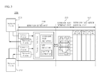
- a basic base (100) includes a network cable (110), an extension manager unit (120), a controller (130), a basic base interface unit (140) and a basic base module mounting unit (150).
- the network cable (110) serves to connect the basic base (100) to at least one extension base (described later).
- the basic base (100) may separately include a connector (not shown) to connect the network cable (110).
- the network cable (110) is exemplified by way of Ethernet cable, the network cable (110) is not limited to the Ethernet cable, and it should be well appreciated by skilled in the art that any type of cables capable of forming a network may be utilized.
- the controller (130) functions to generate a control data for controlling various modules and bases.
- the controller (130) may transmit data to the extension base, or manage or diagnose the extension base.
- the controller (130) may generate an individual control data relative to a plurality of extension bases.
- extension bases are formed with same extension modules, information relative to extension modules installed by the extension bases may be perceived in advance, and a control data for each of the plurality of extension bases may be generated.
- the extension manager unit (120) receives a control data generated by the controller (130) to prepare a network frame for transmitting the control data to the extension base through the network cable (110). That is, the network frame is a frame including the control data and a data capable of being received and transmitted of the control data through the network cable.
- the controller (130) In a case the controller (130) generates an identical control data relative to the plurality of extension bases; the extension manager unit (120) may prepare the network frame free from a destination extension base. Meanwhile, in a case the controller (130) generates an individual control data relative to the plurality of extension bases; the extension manager unit (120) may generate a network frame including a destination flag notifying a control data relative to an extension base in the plurality of extension bases when the network frame is generated.
- the basic base interface unit (140) uses the control data generated by the controller (130) to individually control a module connected to the basic base (100). That is, the module connected to the basic base (100) is operated by the control data inputted from the controller (130) through the basic base interface unit (140).
- the basic base module mounting unit (150) is a configuration capable of mounting all the modules connected to the basic base (100). That is, the basic base module mounting unit (150) physically connects various modules to the basic base (100). For example, although not depicted in FIG.2 , a communication module (not shown) having a function of promoting communication with outside devices, an input/output module (not shown) for controlling input/output may be mounted on the basic base module mounting unit (150). However, it should be well appreciated by skilled in the art that the given configuration is just an example and other configurations may be applied.
- extension manager unit (120) as hardware apart from the controller (130), it should be well appreciated by skilled in the art that, as long as the controller (130) is mounted with a network interface function, the extension manager unit (120) may be included in the controller (130).
- the PLC network extension system may include a plurality of extension bases, and FIG.3 illustrates one of the extension bases.
- the extension base (200) includes a network cable (210), an extension driver unit (220), an extension base interface unit (230) and an extension base module mounting unit (240).
- the network cable (110) serves to connect the extension base (200) to the basic base (100).
- the extension base (200) may separately include a connector (not shown) to connect the network cable (210).
- the network cable (210) is exemplified by way of Ethernet cable, the network cable (210) is not limited to the Ethernet cable, and it should be well appreciated by skilled in the art that any type of cables capable of forming a network may be utilized.
- the extension base (200) can receive a control command from the basic base (100) to completely control the mounted modules, dispensing with dependency on the basic base (100). Furthermore, the extension driver unit (220) can perform a scatter operation that is to be carried out by the controller (130) of the basic base (100), and can enhance the performance of an entire system by dispensing with pause time and by performing an operation capable of performing even without a command or a data from the controller (130) of the basic base (100).
- the PLC network extension system includes one basic base (100) and a plurality (N) of extension bases (200-1 to 200-N).
- the basic base (100) is connected to at least one extension base (200-1) through the network cables (110 and 210).
- the extension base (200-1) connected to the basic base (100) is connected in parallel to each of the plurality of extension bases (200). That is, the plurality of extension bases are connected in parallel in such a way that the extension base (200-1) and the extension base (200-2) are connected by the network cable (210), and the extension base (200-2) and the extension base (200-3) are connected by the network cable (210).
- extension driver unit (220-N) of the last extension base (200-N) is connected to the extension manager unit (120) of the basic base (100) in addition to the extension driver unit ⁇ 220-(N-1) ⁇ , whereby the transmitted network frame may be transmitted to the extension manager unit (120) again to determine whether there is generated an error on the network frame. That is, the extension manager unit (120) may be connected to another extension base (200-N) in addition to the extension base (200-1) that has transmitted the network frame to determine whether there is generated an error on the network frame.
- the network frame is effectively transmitted to the plurality of extension bases (200-1, 200-2, 200-N) using the mapping thus described, and the extension driver unit (220) mounted at each extension base (200-1 to 200-N) can perform the scatter operation that is supposed to be processed by the controller (130) of the basic base (100), and the operation that can be performed in advance without a command or a data from the controller (130) of the basic base (100) can be carried out to dispense with the pause time, whereby an entire system can be enhanced in performance.
- FIG.5 is a flowchart illustrating a flow of network extension method according to an exemplary embodiment of the present disclosure.
- the extension manager unit (120) of the basic base (100) receives a control data from the controller (130) (S300). Thereafter, the extension manager unit (120) prepares a network frame including a control data (S310), and transmits the network frame to the extension base (200) (S320). The transmitted network frame is received by the extension base (200) (S330), and the extension driver unit (220) mounted at the extension base (200) extracts a control data included in the network frame (S340). At this time, in a case the network frame contains a destination flag, the extension driver unit (220) may extract only a control data related to thereto. The extension base (200) controls various mounted modules according to the extracted control data.
- FIG. 6 is a block diagram illustrating an overall structure of a network extension system according to an exemplary embodiment of the present disclosure.
- FIG.6 will briefly explain a flow of control data and structural connection status.
- At least one extension base (200-1) and the basic base (100) are connected via network cables (110 and 210).
- the network cable (210) is exemplified by way of Ethernet cable, the network cable (210) is not limited to the Ethernet cable, and it should be well appreciated by skilled in the art that any type of cables capable of forming a network may be utilized.
- the controller (130) of the basic base (100) may generate a control data for controlling modules mounted at the basic base module mounting unit (150) and transmit a signal of the control data via the basic base interface unit (140). As a result, the basic base (100) can control the mounted modules.
- the controller (130) may generate a control data for controlling the modules mounted at the plurality of extension bases (200) and transmit the control data to the extension manager unit (120).
- the controller (130) may generate an individual control data relative to the plurality of extension bases (200).
- the control data for controlling the plurality of extension bases (200) is transmitted to the extension manager unit (120) from the controller (130) to be generated as a network frame by the extension manager unit (120).
- the network frame thus generated is transmitted to one (200-1) of the plurality of extension bases (200) through the network cables (110 and 210). Furthermore, the extension base (200-1) having received the network frame from the basic base (100) may transmit the network frame to the parallel-connected extension base (200-2) via the network cable (210), and may transmit the network frame generated by the basic base (100) to the plurality of extension base (200).
- extension base (200-N) having finally received the network frame may re-transmit the network frame to the extension manager unit (120) of the basic base (100).
- the extension manager unit (120) having received the network frame may check whether there is generated an error in the course of transmission of the network frame.
- Each extension base (200) includes the extension driver unit (220), where the extension driver unit (220) extracts a control data from the received network frame.
- the network frame contains the individual control data for each extension base (200), that is, in a case a destination flag is contained, each extension base (200) may extract its own control data only.
- the extracted control data is transmitted to the extension base interface unit (230) to be used for controlling the modules mounted on each extension base module mounting unit (240).
Landscapes
- Engineering & Computer Science (AREA)
- Physics & Mathematics (AREA)
- General Physics & Mathematics (AREA)
- Automation & Control Theory (AREA)
- General Engineering & Computer Science (AREA)
- Manufacturing & Machinery (AREA)
- Quality & Reliability (AREA)
- Computer Networks & Wireless Communication (AREA)
- Signal Processing (AREA)
- Computer Security & Cryptography (AREA)
- Programmable Controllers (AREA)
- Cable Transmission Systems, Equalization Of Radio And Reduction Of Echo (AREA)
Applications Claiming Priority (1)
| Application Number | Priority Date | Filing Date | Title |
|---|---|---|---|
| KR1020110081694A KR101240703B1 (ko) | 2011-08-17 | 2011-08-17 | Plc 네트워크 증설방법 및 이를 이용한 네트워크 증설시스템 |
Publications (3)
| Publication Number | Publication Date |
|---|---|
| EP2560061A2 true EP2560061A2 (fr) | 2013-02-20 |
| EP2560061A3 EP2560061A3 (fr) | 2016-10-26 |
| EP2560061B1 EP2560061B1 (fr) | 2020-04-22 |
Family
ID=46724222
Family Applications (1)
| Application Number | Title | Priority Date | Filing Date |
|---|---|---|---|
| EP12175878.3A Active EP2560061B1 (fr) | 2011-08-17 | 2012-07-11 | Système d'élargir un réseau plc |
Country Status (5)
| Country | Link |
|---|---|
| US (1) | US9360862B2 (fr) |
| EP (1) | EP2560061B1 (fr) |
| KR (1) | KR101240703B1 (fr) |
| CN (1) | CN102955444B (fr) |
| ES (1) | ES2804505T3 (fr) |
Cited By (1)
| Publication number | Priority date | Publication date | Assignee | Title |
|---|---|---|---|---|
| CN106506304A (zh) * | 2016-10-17 | 2017-03-15 | 浙江中控技术股份有限公司 | 可扩展的通信系统及方法 |
Families Citing this family (4)
| Publication number | Priority date | Publication date | Assignee | Title |
|---|---|---|---|---|
| CN105527919A (zh) * | 2016-01-26 | 2016-04-27 | 上海海得控制系统股份有限公司 | 一种plc控制器的并行总线背板 |
| JP6865912B1 (ja) * | 2020-07-06 | 2021-04-28 | 三菱電機株式会社 | 入出力モジュール、標準入出力モジュールユニット、および、安全回路ユニット |
| TWI872562B (zh) * | 2020-12-29 | 2025-02-11 | 東碩資訊股份有限公司 | 用以進行簽到及簽退的控制方法 |
| WO2022202389A1 (fr) * | 2021-03-24 | 2022-09-29 | ファナック株式会社 | Unité maître et système de communication |
Family Cites Families (13)
| Publication number | Priority date | Publication date | Assignee | Title |
|---|---|---|---|---|
| JP4494617B2 (ja) | 2000-10-02 | 2010-06-30 | 株式会社キーエンス | プログラマブルコントローラシステム |
| US6914914B1 (en) * | 2001-05-22 | 2005-07-05 | Rockwell Automation Technologies, Inc. | System and method for multi-chassis configurable time synchronization |
| KR100479640B1 (ko) * | 2003-04-23 | 2005-03-31 | 주식회사 케이디티 시스템즈 | 직렬통신에 의한 프로그래머블 로직 제어장치의 증설시스템과 그 동작방법 |
| JP4647951B2 (ja) * | 2004-07-29 | 2011-03-09 | 株式会社ジェイテクト | 安全制御装置、安全制御システム及び通信エラー検出方法 |
| CN1719363A (zh) | 2005-07-27 | 2006-01-11 | 艾默生网络能源有限公司 | 可编程逻辑控制器硬件扩展方法 |
| US7484019B2 (en) * | 2005-12-09 | 2009-01-27 | Delta Electronics, Inc. | Expansion system that automatically allows or blocks data from the PLC host using a clamping and decoding circuit to output clamping value |
| JP2008046702A (ja) * | 2006-08-11 | 2008-02-28 | Omron Corp | Plc装置 |
| JP4952228B2 (ja) * | 2006-12-18 | 2012-06-13 | 株式会社ジェイテクト | Plc分散制御システム |
| CN201170857Y (zh) * | 2007-08-21 | 2008-12-24 | 国电南京自动化股份有限公司 | 可编程逻辑控制器 |
| KR101218003B1 (ko) * | 2008-06-02 | 2013-01-02 | 미쓰비시덴키 가부시키가이샤 | 데이터 통신 시스템 및 데이터 통신 장치 |
| JP4651726B2 (ja) | 2009-04-24 | 2011-03-16 | 三菱電機株式会社 | ユニット形プログラマブルコントローラ |
| CN101592934A (zh) | 2009-06-30 | 2009-12-02 | 上海电器科学研究所(集团)有限公司 | 可编程逻辑控制器与扩展模块的通信方法 |
| JP5408445B2 (ja) * | 2010-03-15 | 2014-02-05 | オムロン株式会社 | プログラマブルコントローラおよびマスタ通信回路 |
-
2011
- 2011-08-17 KR KR1020110081694A patent/KR101240703B1/ko active Active
-
2012
- 2012-07-11 EP EP12175878.3A patent/EP2560061B1/fr active Active
- 2012-07-11 ES ES12175878T patent/ES2804505T3/es active Active
- 2012-07-16 US US13/550,370 patent/US9360862B2/en active Active
- 2012-07-31 CN CN201210271305.7A patent/CN102955444B/zh active Active
Non-Patent Citations (1)
| Title |
|---|
| None |
Cited By (1)
| Publication number | Priority date | Publication date | Assignee | Title |
|---|---|---|---|---|
| CN106506304A (zh) * | 2016-10-17 | 2017-03-15 | 浙江中控技术股份有限公司 | 可扩展的通信系统及方法 |
Also Published As
| Publication number | Publication date |
|---|---|
| EP2560061B1 (fr) | 2020-04-22 |
| EP2560061A3 (fr) | 2016-10-26 |
| US20130044632A1 (en) | 2013-02-21 |
| ES2804505T3 (es) | 2021-02-08 |
| KR101240703B1 (ko) | 2013-03-11 |
| KR20130019617A (ko) | 2013-02-27 |
| CN102955444A (zh) | 2013-03-06 |
| CN102955444B (zh) | 2016-01-20 |
| US9360862B2 (en) | 2016-06-07 |
Similar Documents
| Publication | Publication Date | Title |
|---|---|---|
| US9360862B2 (en) | PLC network extension system | |
| US8509927B2 (en) | Control system for controlling safety-critical processes | |
| EP1691245A1 (fr) | Automatisation sur base de composants | |
| US8543370B2 (en) | Multiple PLC simulation system | |
| US8549136B2 (en) | System for operating at least one non-safety-critical and at least one safety-critical process | |
| KR20120132510A (ko) | 유체 액추에이터를 제어하기 위한 장치 및 방법 | |
| US11022962B2 (en) | High availability industrial automation system having primary and secondary industrial automation controllers and method of communicating information over the same | |
| US10805116B2 (en) | Gateway and method for connecting a data source system to an IT system | |
| US8943188B2 (en) | Automation network comprising network components that produce status messages | |
| EP3360399A1 (fr) | Collecteur de soupape monté en série à un ensemble système de commande réparti | |
| CN102478804A (zh) | 可编程逻辑控制器系统 | |
| US10938967B2 (en) | Method and apparatus for communication in a motor drive application | |
| EP3656512A1 (fr) | Dispositif, système et procédé d'intégration prête à l'emploi de composants dans des systèmes robotiques | |
| CN103797758A (zh) | 用于自动化系统的通信接口模块 | |
| CN111213344B (zh) | 用于操作自动化技术设施的方法 | |
| US10289572B2 (en) | Industrial control adjacent input-output modules and methods thereof | |
| KR101273812B1 (ko) | 피엘씨 일체형 제어모듈 및 이를 이용한 피엘씨 제어 시스템 | |
| US20250328120A1 (en) | Programmable logic controller with fail-safe input/output expansion within central processing unit | |
| Young | A fieldbus approach to robotic systems reconfiguration | |
| Yamashita et al. | Distributed Remote Input/Output Control Method in Real Time Processing for CNC | |
| CN121713128A (zh) | 功能非安全标准模块的安全相关关机 | |
| KR20170111207A (ko) | 데이터 변경 감지 모드를 이용한 plc 시스템 | |
| WO2025183670A1 (fr) | Module à fonction de sécurité intégrée pour diminuer le temps de réaction de sécurité | |
| Stank | Bridging safety onto automation networks | |
| KR20210012319A (ko) | Bus 구조를 가지는 공장 자동화 제어 시스템 |
Legal Events
| Date | Code | Title | Description |
|---|---|---|---|
| PUAI | Public reference made under article 153(3) epc to a published international application that has entered the european phase |
Free format text: ORIGINAL CODE: 0009012 |
|
| AK | Designated contracting states |
Kind code of ref document: A2 Designated state(s): AL AT BE BG CH CY CZ DE DK EE ES FI FR GB GR HR HU IE IS IT LI LT LU LV MC MK MT NL NO PL PT RO RS SE SI SK SM TR |
|
| AX | Request for extension of the european patent |
Extension state: BA ME |
|
| REG | Reference to a national code |
Ref country code: DE Ref legal event code: R079 Ref document number: 602012069415 Country of ref document: DE Free format text: PREVIOUS MAIN CLASS: G05B0019418000 Ipc: G05B0019050000 |
|
| PUAL | Search report despatched |
Free format text: ORIGINAL CODE: 0009013 |
|
| AK | Designated contracting states |
Kind code of ref document: A3 Designated state(s): AL AT BE BG CH CY CZ DE DK EE ES FI FR GB GR HR HU IE IS IT LI LT LU LV MC MK MT NL NO PL PT RO RS SE SI SK SM TR |
|
| AX | Request for extension of the european patent |
Extension state: BA ME |
|
| RIC1 | Information provided on ipc code assigned before grant |
Ipc: G05B 19/05 20060101AFI20160921BHEP |
|
| STAA | Information on the status of an ep patent application or granted ep patent |
Free format text: STATUS: REQUEST FOR EXAMINATION WAS MADE |
|
| 17P | Request for examination filed |
Effective date: 20170420 |
|
| RBV | Designated contracting states (corrected) |
Designated state(s): AL AT BE BG CH CY CZ DE DK EE ES FI FR GB GR HR HU IE IS IT LI LT LU LV MC MK MT NL NO PL PT RO RS SE SI SK SM TR |
|
| STAA | Information on the status of an ep patent application or granted ep patent |
Free format text: STATUS: EXAMINATION IS IN PROGRESS |
|
| 17Q | First examination report despatched |
Effective date: 20181026 |
|
| GRAP | Despatch of communication of intention to grant a patent |
Free format text: ORIGINAL CODE: EPIDOSNIGR1 |
|
| STAA | Information on the status of an ep patent application or granted ep patent |
Free format text: STATUS: GRANT OF PATENT IS INTENDED |
|
| INTG | Intention to grant announced |
Effective date: 20191219 |
|
| RAP1 | Party data changed (applicant data changed or rights of an application transferred) |
Owner name: LSIS CO., LTD. |
|
| RIN1 | Information on inventor provided before grant (corrected) |
Inventor name: OH, JOON SEOK Inventor name: YOON, GEON |
|
| GRAS | Grant fee paid |
Free format text: ORIGINAL CODE: EPIDOSNIGR3 |
|
| GRAA | (expected) grant |
Free format text: ORIGINAL CODE: 0009210 |
|
| STAA | Information on the status of an ep patent application or granted ep patent |
Free format text: STATUS: THE PATENT HAS BEEN GRANTED |
|
| AK | Designated contracting states |
Kind code of ref document: B1 Designated state(s): AL AT BE BG CH CY CZ DE DK EE ES FI FR GB GR HR HU IE IS IT LI LT LU LV MC MK MT NL NO PL PT RO RS SE SI SK SM TR |
|
| REG | Reference to a national code |
Ref country code: GB Ref legal event code: FG4D |
|
| REG | Reference to a national code |
Ref country code: CH Ref legal event code: EP |
|
| REG | Reference to a national code |
Ref country code: IE Ref legal event code: FG4D |
|
| REG | Reference to a national code |
Ref country code: DE Ref legal event code: R096 Ref document number: 602012069415 Country of ref document: DE |
|
| REG | Reference to a national code |
Ref country code: AT Ref legal event code: REF Ref document number: 1260950 Country of ref document: AT Kind code of ref document: T Effective date: 20200515 |
|
| REG | Reference to a national code |
Ref country code: LT Ref legal event code: MG4D |
|
| REG | Reference to a national code |
Ref country code: NL Ref legal event code: MP Effective date: 20200422 |
|
| PG25 | Lapsed in a contracting state [announced via postgrant information from national office to epo] |
Ref country code: SE Free format text: LAPSE BECAUSE OF FAILURE TO SUBMIT A TRANSLATION OF THE DESCRIPTION OR TO PAY THE FEE WITHIN THE PRESCRIBED TIME-LIMIT Effective date: 20200422 Ref country code: NO Free format text: LAPSE BECAUSE OF FAILURE TO SUBMIT A TRANSLATION OF THE DESCRIPTION OR TO PAY THE FEE WITHIN THE PRESCRIBED TIME-LIMIT Effective date: 20200722 Ref country code: IS Free format text: LAPSE BECAUSE OF FAILURE TO SUBMIT A TRANSLATION OF THE DESCRIPTION OR TO PAY THE FEE WITHIN THE PRESCRIBED TIME-LIMIT Effective date: 20200822 Ref country code: GR Free format text: LAPSE BECAUSE OF FAILURE TO SUBMIT A TRANSLATION OF THE DESCRIPTION OR TO PAY THE FEE WITHIN THE PRESCRIBED TIME-LIMIT Effective date: 20200723 Ref country code: FI Free format text: LAPSE BECAUSE OF FAILURE TO SUBMIT A TRANSLATION OF THE DESCRIPTION OR TO PAY THE FEE WITHIN THE PRESCRIBED TIME-LIMIT Effective date: 20200422 Ref country code: LT Free format text: LAPSE BECAUSE OF FAILURE TO SUBMIT A TRANSLATION OF THE DESCRIPTION OR TO PAY THE FEE WITHIN THE PRESCRIBED TIME-LIMIT Effective date: 20200422 Ref country code: NL Free format text: LAPSE BECAUSE OF FAILURE TO SUBMIT A TRANSLATION OF THE DESCRIPTION OR TO PAY THE FEE WITHIN THE PRESCRIBED TIME-LIMIT Effective date: 20200422 Ref country code: PT Free format text: LAPSE BECAUSE OF FAILURE TO SUBMIT A TRANSLATION OF THE DESCRIPTION OR TO PAY THE FEE WITHIN THE PRESCRIBED TIME-LIMIT Effective date: 20200824 |
|
| REG | Reference to a national code |
Ref country code: AT Ref legal event code: MK05 Ref document number: 1260950 Country of ref document: AT Kind code of ref document: T Effective date: 20200422 |
|
| PG25 | Lapsed in a contracting state [announced via postgrant information from national office to epo] |
Ref country code: LV Free format text: LAPSE BECAUSE OF FAILURE TO SUBMIT A TRANSLATION OF THE DESCRIPTION OR TO PAY THE FEE WITHIN THE PRESCRIBED TIME-LIMIT Effective date: 20200422 Ref country code: HR Free format text: LAPSE BECAUSE OF FAILURE TO SUBMIT A TRANSLATION OF THE DESCRIPTION OR TO PAY THE FEE WITHIN THE PRESCRIBED TIME-LIMIT Effective date: 20200422 Ref country code: RS Free format text: LAPSE BECAUSE OF FAILURE TO SUBMIT A TRANSLATION OF THE DESCRIPTION OR TO PAY THE FEE WITHIN THE PRESCRIBED TIME-LIMIT Effective date: 20200422 Ref country code: BG Free format text: LAPSE BECAUSE OF FAILURE TO SUBMIT A TRANSLATION OF THE DESCRIPTION OR TO PAY THE FEE WITHIN THE PRESCRIBED TIME-LIMIT Effective date: 20200722 |
|
| PG25 | Lapsed in a contracting state [announced via postgrant information from national office to epo] |
Ref country code: AL Free format text: LAPSE BECAUSE OF FAILURE TO SUBMIT A TRANSLATION OF THE DESCRIPTION OR TO PAY THE FEE WITHIN THE PRESCRIBED TIME-LIMIT Effective date: 20200422 |
|
| REG | Reference to a national code |
Ref country code: DE Ref legal event code: R097 Ref document number: 602012069415 Country of ref document: DE |
|
| PG25 | Lapsed in a contracting state [announced via postgrant information from national office to epo] |
Ref country code: EE Free format text: LAPSE BECAUSE OF FAILURE TO SUBMIT A TRANSLATION OF THE DESCRIPTION OR TO PAY THE FEE WITHIN THE PRESCRIBED TIME-LIMIT Effective date: 20200422 Ref country code: SM Free format text: LAPSE BECAUSE OF FAILURE TO SUBMIT A TRANSLATION OF THE DESCRIPTION OR TO PAY THE FEE WITHIN THE PRESCRIBED TIME-LIMIT Effective date: 20200422 Ref country code: DK Free format text: LAPSE BECAUSE OF FAILURE TO SUBMIT A TRANSLATION OF THE DESCRIPTION OR TO PAY THE FEE WITHIN THE PRESCRIBED TIME-LIMIT Effective date: 20200422 Ref country code: CZ Free format text: LAPSE BECAUSE OF FAILURE TO SUBMIT A TRANSLATION OF THE DESCRIPTION OR TO PAY THE FEE WITHIN THE PRESCRIBED TIME-LIMIT Effective date: 20200422 Ref country code: AT Free format text: LAPSE BECAUSE OF FAILURE TO SUBMIT A TRANSLATION OF THE DESCRIPTION OR TO PAY THE FEE WITHIN THE PRESCRIBED TIME-LIMIT Effective date: 20200422 Ref country code: RO Free format text: LAPSE BECAUSE OF FAILURE TO SUBMIT A TRANSLATION OF THE DESCRIPTION OR TO PAY THE FEE WITHIN THE PRESCRIBED TIME-LIMIT Effective date: 20200422 |
|
| REG | Reference to a national code |
Ref country code: ES Ref legal event code: FG2A Ref document number: 2804505 Country of ref document: ES Kind code of ref document: T3 Effective date: 20210208 |
|
| PG25 | Lapsed in a contracting state [announced via postgrant information from national office to epo] |
Ref country code: PL Free format text: LAPSE BECAUSE OF FAILURE TO SUBMIT A TRANSLATION OF THE DESCRIPTION OR TO PAY THE FEE WITHIN THE PRESCRIBED TIME-LIMIT Effective date: 20200422 Ref country code: MC Free format text: LAPSE BECAUSE OF FAILURE TO SUBMIT A TRANSLATION OF THE DESCRIPTION OR TO PAY THE FEE WITHIN THE PRESCRIBED TIME-LIMIT Effective date: 20200422 Ref country code: SK Free format text: LAPSE BECAUSE OF FAILURE TO SUBMIT A TRANSLATION OF THE DESCRIPTION OR TO PAY THE FEE WITHIN THE PRESCRIBED TIME-LIMIT Effective date: 20200422 |
|
| PLBE | No opposition filed within time limit |
Free format text: ORIGINAL CODE: 0009261 |
|
| REG | Reference to a national code |
Ref country code: CH Ref legal event code: PL |
|
| STAA | Information on the status of an ep patent application or granted ep patent |
Free format text: STATUS: NO OPPOSITION FILED WITHIN TIME LIMIT |
|
| 26N | No opposition filed |
Effective date: 20210125 |
|
| REG | Reference to a national code |
Ref country code: BE Ref legal event code: MM Effective date: 20200731 |
|
| PG25 | Lapsed in a contracting state [announced via postgrant information from national office to epo] |
Ref country code: LU Free format text: LAPSE BECAUSE OF NON-PAYMENT OF DUE FEES Effective date: 20200711 Ref country code: CH Free format text: LAPSE BECAUSE OF NON-PAYMENT OF DUE FEES Effective date: 20200731 Ref country code: LI Free format text: LAPSE BECAUSE OF NON-PAYMENT OF DUE FEES Effective date: 20200731 |
|
| PG25 | Lapsed in a contracting state [announced via postgrant information from national office to epo] |
Ref country code: BE Free format text: LAPSE BECAUSE OF NON-PAYMENT OF DUE FEES Effective date: 20200731 Ref country code: SI Free format text: LAPSE BECAUSE OF FAILURE TO SUBMIT A TRANSLATION OF THE DESCRIPTION OR TO PAY THE FEE WITHIN THE PRESCRIBED TIME-LIMIT Effective date: 20200422 |
|
| PG25 | Lapsed in a contracting state [announced via postgrant information from national office to epo] |
Ref country code: IE Free format text: LAPSE BECAUSE OF NON-PAYMENT OF DUE FEES Effective date: 20200711 |
|
| PG25 | Lapsed in a contracting state [announced via postgrant information from national office to epo] |
Ref country code: TR Free format text: LAPSE BECAUSE OF FAILURE TO SUBMIT A TRANSLATION OF THE DESCRIPTION OR TO PAY THE FEE WITHIN THE PRESCRIBED TIME-LIMIT Effective date: 20200422 Ref country code: MT Free format text: LAPSE BECAUSE OF FAILURE TO SUBMIT A TRANSLATION OF THE DESCRIPTION OR TO PAY THE FEE WITHIN THE PRESCRIBED TIME-LIMIT Effective date: 20200422 Ref country code: CY Free format text: LAPSE BECAUSE OF FAILURE TO SUBMIT A TRANSLATION OF THE DESCRIPTION OR TO PAY THE FEE WITHIN THE PRESCRIBED TIME-LIMIT Effective date: 20200422 |
|
| PG25 | Lapsed in a contracting state [announced via postgrant information from national office to epo] |
Ref country code: MK Free format text: LAPSE BECAUSE OF FAILURE TO SUBMIT A TRANSLATION OF THE DESCRIPTION OR TO PAY THE FEE WITHIN THE PRESCRIBED TIME-LIMIT Effective date: 20200422 |
|
| P01 | Opt-out of the competence of the unified patent court (upc) registered |
Effective date: 20230625 |
|
| PGFP | Annual fee paid to national office [announced via postgrant information from national office to epo] |
Ref country code: GB Payment date: 20250610 Year of fee payment: 14 |
|
| PGFP | Annual fee paid to national office [announced via postgrant information from national office to epo] |
Ref country code: FR Payment date: 20250611 Year of fee payment: 14 |
|
| PGFP | Annual fee paid to national office [announced via postgrant information from national office to epo] |
Ref country code: ES Payment date: 20250822 Year of fee payment: 14 |
|
| PGFP | Annual fee paid to national office [announced via postgrant information from national office to epo] |
Ref country code: DE Payment date: 20250609 Year of fee payment: 14 |
|
| PGFP | Annual fee paid to national office [announced via postgrant information from national office to epo] |
Ref country code: IT Payment date: 20250610 Year of fee payment: 14 |