EP2560062A1 - Procédés et systèmes de contrôle pour contrôler un système industriel - Google Patents
Procédés et systèmes de contrôle pour contrôler un système industriel Download PDFInfo
- Publication number
- EP2560062A1 EP2560062A1 EP11177627A EP11177627A EP2560062A1 EP 2560062 A1 EP2560062 A1 EP 2560062A1 EP 11177627 A EP11177627 A EP 11177627A EP 11177627 A EP11177627 A EP 11177627A EP 2560062 A1 EP2560062 A1 EP 2560062A1
- Authority
- EP
- European Patent Office
- Prior art keywords
- status
- status value
- value
- process variable
- values
- Prior art date
- Legal status (The legal status is an assumption and is not a legal conclusion. Google has not performed a legal analysis and makes no representation as to the accuracy of the status listed.)
- Ceased
Links
Images


Classifications
-
- G—PHYSICS
- G05—CONTROLLING; REGULATING
- G05B—CONTROL OR REGULATING SYSTEMS IN GENERAL; FUNCTIONAL ELEMENTS OF SUCH SYSTEMS; MONITORING OR TESTING ARRANGEMENTS FOR SUCH SYSTEMS OR ELEMENTS
- G05B13/00—Adaptive control systems, i.e. systems automatically adjusting themselves to have a performance which is optimum according to some preassigned criterion
- G05B13/02—Adaptive control systems, i.e. systems automatically adjusting themselves to have a performance which is optimum according to some preassigned criterion electric
-
- G—PHYSICS
- G05—CONTROLLING; REGULATING
- G05B—CONTROL OR REGULATING SYSTEMS IN GENERAL; FUNCTIONAL ELEMENTS OF SUCH SYSTEMS; MONITORING OR TESTING ARRANGEMENTS FOR SUCH SYSTEMS OR ELEMENTS
- G05B23/00—Testing or monitoring of control systems or parts thereof
- G05B23/02—Electric testing or monitoring
- G05B23/0205—Electric testing or monitoring by means of a monitoring system capable of detecting and responding to faults
- G05B23/0218—Electric testing or monitoring by means of a monitoring system capable of detecting and responding to faults characterised by the fault detection method dealing with either existing or incipient faults
- G05B23/0224—Process history based detection method, e.g. whereby history implies the availability of large amounts of data
- G05B23/0227—Qualitative history assessment, whereby the type of data acted upon, e.g. waveforms, images or patterns, is not relevant, e.g. rule based assessment; if-then decisions
- G05B23/0235—Qualitative history assessment, whereby the type of data acted upon, e.g. waveforms, images or patterns, is not relevant, e.g. rule based assessment; if-then decisions based on a comparison with predetermined threshold or range, e.g. "classical methods", carried out during normal operation; threshold adaptation or choice; when or how to compare with the threshold
-
- G—PHYSICS
- G05—CONTROLLING; REGULATING
- G05B—CONTROL OR REGULATING SYSTEMS IN GENERAL; FUNCTIONAL ELEMENTS OF SUCH SYSTEMS; MONITORING OR TESTING ARRANGEMENTS FOR SUCH SYSTEMS OR ELEMENTS
- G05B23/00—Testing or monitoring of control systems or parts thereof
- G05B23/02—Electric testing or monitoring
- G05B23/0205—Electric testing or monitoring by means of a monitoring system capable of detecting and responding to faults
- G05B23/0259—Electric testing or monitoring by means of a monitoring system capable of detecting and responding to faults characterized by the response to fault detection
- G05B23/0267—Fault communication, e.g. human machine interface [HMI]
- G05B23/0272—Presentation of monitored results, e.g. selection of status reports to be displayed; Filtering information to the user
-
- G—PHYSICS
- G05—CONTROLLING; REGULATING
- G05B—CONTROL OR REGULATING SYSTEMS IN GENERAL; FUNCTIONAL ELEMENTS OF SUCH SYSTEMS; MONITORING OR TESTING ARRANGEMENTS FOR SUCH SYSTEMS OR ELEMENTS
- G05B23/00—Testing or monitoring of control systems or parts thereof
- G05B23/02—Electric testing or monitoring
- G05B23/0205—Electric testing or monitoring by means of a monitoring system capable of detecting and responding to faults
- G05B23/0259—Electric testing or monitoring by means of a monitoring system capable of detecting and responding to faults characterized by the response to fault detection
- G05B23/0286—Modifications to the monitored process, e.g. stopping operation or adapting control
- G05B23/0294—Optimizing process, e.g. process efficiency, product quality
Definitions
- the present disclosure generally relates to monitoring and control of an industrial system, and in particular to methods and control systems for facilitating control of an industrial system.
- Operators may thereby be able to recognize an alarm or a trend in the industrial system and, as a result, take measures to solve the problem giving rise to the alarm or trend.
- a general object of the present disclosure is to provide a method and a control system which improves the work environment for system operators.
- a method of controlling an industrial system by means of a control system comprising a display unit, wherein the method comprises: receiving status-related data pertaining to a status of a plurality of process variables in the industrial system; determining a status value for each of the plurality of process variables based on the status-related data; adjusting the status value for each of the plurality of process variables, thereby forming adjusted status values for each of the plurality of process variables, wherein the adjusting is performed in such a way that an adjusted status value is set to be within a predefined range of values if the associated process variable is in a normal state, and wherein an adjusted status value is set to have a value outside the predefined range of values if the associated process variable is in a state deviating from the normal state; displaying, on the display unit, the adjusted status value of each of the plurality of process variables in a common data plot, and if at least one adjusted status value has a value outside the predefined range; receiving a
- the industrial system may in one embodiment enable the operation of an industrial process.
- the adjusting the status value comprises normalising the status values.
- On embodiment comprises normalising the status values with respect to respective set point values.
- a computer program product comprising computer-executable components for causing a device to perform the steps recited above when the computer-executable components are run on a processing unit included in the device.
- a control system for controlling an industrial system, wherein the control system comprises: a communications unit arranged to receive status-related data pertaining to a status of a plurality of process variables in the industrial system; a processing unit arranged to determining a status value for each of the plurality of process variables based on the status-related data, and to adjust the status value for each of the plurality of process variables, thereby forming adjusted status values for each of the plurality of process variables, wherein the processing unit is arranged to adjust the status values in such a way that an adjusted status value is set to be within a predefined range of values if the associated process variable is in a normal state, and wherein an adjusted status value is set to have a value outside the predefined range of values if the associated process variable is in a state deviating from the normal state; and a display unit arranged to display the adjusted status value of each of the plurality of process variables in a common data plot wherein the control system is arranged to receive a user input
- the processing unit is arranged to adjust the status values by normalising the status values.
- the processing unit is arranged to normalise the status values with respect to respective set point values.
- a method of controlling an industrial system by means of a control system comprising a display unit, wherein the method comprises: receiving status-related data pertaining to a status of a plurality of process variables in the industrial system, determining a status value for each of the plurality of process variables based on the status-related data; displaying, on the display unit, the status value of each of the plurality of process variables in a data plot, repeating the steps of receiving and determining; indicating that the status value is outside the predetermined accepted range by adjusting the appearance of the status value according to a first predetermined appearance adjustment on the display unit; indicating that the status value is outside the predetermined accepted range by adjusting the appearance of the status value according to a first predetermined appearance adjustment on the display unit; receiving a user input for controlling the process variable associated with the status value having been subject to the first type of status change; and controlling the process variable based on the user input.
- the monitoring of the industrial system is thereby simplified.
- the severity of an alarm situation can be reduced since the user can act quickly after the alarm has appeared, even if a plurality of process variables is being monitored simultaneously. Consequently, it is envisaged that alarm-related wear can be avoided in the equipment of the industrial system.
- One embodiment comprises detecting a status value change, which change provides a status value inside the predetermined accepted range of status values for the associated process variable, and adjusting the appearance, on the display unit, of the status value according to a second predetermined appearance adjustment.
- the first predetermined appearance adjustment provides an indication of an alarm associated with the process variable.
- the second predetermined appearance adjustment provides an indication of a trend associated with the process variable.
- a computer program product comprising computer-executable components for causing a device to perform the steps above with respect to the third aspect when the computer-executable components are run on a processing unit included in the device.
- a control system for controlling an industrial system, wherein the control system comprises: a communications unit arranged to receive status-related data pertaining to a status of a plurality of process variables in the industrial system; a processing unit arranged to determine a status value for each of the plurality of process variables based on the status-related data; and a display unit arranged to display the status value for each of the plurality of process variables in a data plot; wherein the control system is arranged to repeatedly receive status-related data and determine status values for each of the plurality of process variables based on the status-related data, wherein the control system is arranged to repeatedly receive status-related data and determine status values for each of the plurality of process variables based on the status-related data, and to detect if a status value of a process variable is outside a predetermined accepted range of status values for the associated process variable; wherein the display unit is arranged to indicate that the status value is outside the predetermined accepted range as a result of the processing unit being arranged
- control system is arranged to detect a status value change, which change provides a status value inside the predetermined accepted range of status values for the associated process variable, and adjusting the appearance, on the display unit, of the status value according to a second predetermined appearance adjustment.
- the first predetermined appearance adjustment provides an indication of an alarm associated with the process variable.
- the second predetermined appearance adjustment provides an indication of a trend associated with the process variable.
- Fig. 1 schematically shows an industrial system 1 and a control system 3 arranged to be in communication with the industrial system 1 for monitoring and controlling the industrial system 1.
- An industrial system may in this context for instance be an electric grid or a part thereof, a pulp and paper mill, an oil refinery, a thermal power plant, a nuclear power plant, a wind farm or any production system in the process industry. It is to be noted that the present inventive concept can be utilised for monitoring and/or controlling many different types of industrial systems, with only a few examples having been given above.
- the industrial system comprises a plurality of tanks 1-A, valves 1-B for regulating the pressure and thus the temperature in the tanks 1-A, and sensors 1-C for measuring e.g. the pressure in the tanks 1-A.
- the process flow is in the direction of the arrow A, i.e. from the right to the left in the drawing.
- Each object e.g. a tank or valve of the industrial system 1 has one or more object properties which can be measured and controlled. Such an object property will herein be referred to as a process variable.
- a process variable of a tank 1-A can for instance, and as already mentioned, be the tank pressure.
- the pressure in the tank 1-A can for instance be measured by means of its associated sensor 1-C.
- Each sensor can sense the process variable which it is arranged to measure, wherein status-related data of the process variable can be communicated to the control system 3. This way, data comprising information regarding a plurality of process variables y1, y2, y3, y4, y5 can be communicated to the control system 3 by means of a plurality of sensors 1-C.
- the control system 3 comprises a communications unit 5 arranged to receive the status-related data from the sensors 1-C of the industrial system 1 and to provide control signals to the industrial system 1, a processing unit 7, a display unit 9, and an input unit 11.
- the processing unit 7 may be arranged to process the status-related data received by the communications unit 5.
- the display unit 9 is operatively connected to the processing unit 7 such that for instance the processed status-related data can be displayed by the display unit 9.
- a user interface 10 defined by the display unit 9 and the input unit 11 allows a user such as an operator to interact with the industrial system 1.
- a user provides a user input via the input unit 11, which is subsequently processed by the processing unit 7.
- the user interface 10 allows for monitoring and control of the industrial system 1 via the control system 3.
- the display unit is also the input unit.
- the display unit may be a touch-screen device.
- the input unit may be a gesture-based detection unit arranged to detect gestured-based input by a user.
- the input unit may be a mouse, a keyboard or any other similar traditional input means.
- the control system 3 comprises software for processing the status-related data and control software for controlling the industrial system 1 via the communications unit 5 for instance by generating control signals based on user input received from the input unit 11.
- the processing unit 7 comprises the above-mentioned software.
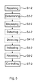
- a first embodiment of a method of controlling an industrial system, such as the industrial system 1, will now be described in more detail with reference to Figs 2a-b , and Fig. 3 .
- a first step S1-1 status-related data pertaining to at least one process variable, but typically a plurality of process variables, is received by the communications unit 5.
- the processing unit 7 receives the status-related data from the communications unit 5 and processes the status-related data such that it can be displayed on the display unit 9 in a way which provides an easy overview of the status of each process variable. It is envisaged that all process variables of the industrial system 1 can be presented in an easily comprehendible way to a user.
- a user monitoring the industrial system 1 can easily detect an abnormal situation with respect to one or more process variables. To this end, the user can act to control the affected process variable essentially as soon as the abnormal situation has occurred.
- a second step S2-1 the processing unit 7 is arranged to determine a status value for each process variables for which status-related data has been received, based on the status-related data.
- the processing unit 7 is arranged to adjust the status value for each process variable in a step S3-1. Thereby an adjusted status value is formed for each of the plurality of process variables.
- the step S3-1 of adjusting is performed in such a way that an adjusted status value is set to be within a predefined range of values if the associated process variable is in a normal state. Moreover, an adjusted status value is set to have a value outside the predefined range of values if the associated process variable is in a state deviating from the normal state. Such a situation occurs due to an abnormal situation in the industrial system. If an abnormal situation occurs, the process variable being subject to the abnormal situation, and hence the status value of the process variable reflects the abnormal situation.
- the step of adjusting S3-1 the status value comprises normalising the status values.
- the normalising of the status values can for instance be made with respect to a respective set point value relative the actual value measured by a sensor 1-C.
- the adjusted status value of each of the plurality of process variables is displayed in a common data plot on the display unit 9, as shown in Fig. 2a .
- the step S3-1 of adjusting results in adjusted status value curves C-1, C-2, C-3, each comprising the adjusted status values for a specific process variable, which propagate in time in an essentially uniform manner when all the process variables are in a normal state. Each curve is typically associated with one distinct process variable.
- the curve C-1 can for instance describe a pressure curve for a tank 1-A with the set point of the pressure, i.e. the associated process variable, varying in time.
- the curves C-2 and C-3 describe other process variables.
- the curves C-1, C-2 and C-3 are preferably presented in such a way that a user easily can distinguish between them even during normal operation when the curves essentially overlap, as shown in Fig. 2a .
- each curve can have different colour.
- one curve can be dashed, another curve can be an unbroken line and so on, as would be apparent to the skilled person.
- a user input may be provided by a user via the input device 11 in order to obtain control the affected equipment in the industrial system and hence of the abnormal situation which has occurred.
- Fig. 2b depicts the curves C-1, C-2 and C-3 in a common plot after a time t 1 when an abnormal situation has occurred influencing the process variable represented in curve C-1.
- the curve C-1 deviates from the curves C-2 and C-3. This way, a user e.g. an operator can easily recognize that an abnormal situation has occurred and that the process variable associated with the curve C-1 should be controlled such that the process variable retains its set point value.
- the processing unit 7 receives the user input comprising input data in a step S5-1, wherein the processing unit 7 can determine a suitable control signal for controlling the process variable associated with the at least one adjusted status value based on the user input.
- the control system 3 controls the process variable based on the user input.
- the above process is typically continually repeated when the industrial system 1 is in operation.
- new status-related data is received continually, e.g. at predetermined intervals or essentially continuously.
- a first step S1-2 status-related data pertaining to at least one process variable, but typically a plurality of process variables, is received by the communications unit 5.
- the processing unit 7 receives the status-related data from the communications unit 5 and processes the status-related data such that it can be displayed on the display unit 9 in a way which provides an easy overview of the status of each process variable received by the communications unit 5, typically all process variables of the industrial system 1.
- a second step S2-2 the processing unit 7 is arranged to determine a status value for each of the plurality of process variables based on the status-related data.
- a third step S3-2 the display unit 9 displays the status value of each of the plurality of process variables in a data plot.
- Each dot in Figs 4a-b represents a status value, but for clearness only two status values 13-1 and 13-2 are referred to with reference numbers.
- the status values 13-1 and 13-2 have been determined to have values V1-1 and V2-1 respectively.
- the steps of receiving S1-2 and determining S2-2 is repeated such that up-to-date status values can be presented on the display unit 9.
- the steps S1-2 and S2-2 are continually repeated when the industrial system 1 is in operation.
- new status-related data is received continually, e.g. at predetermined intervals or essentially continuously.
- the new values V1-2 and V2-2 for status values 13-1 and 13-2, respectively, are determined for the associated process variables
- the new values V2-1 and V2-2 are displayed on the display screen 9.
- the new value V1-2 is outside a predetermined range of status values for the associated process variable, which is shown in Figs 4a and 4b by means of a predetermined upper limit UL and a predetermined lower limit LL defining a predetermined range of acceptable status values within a normal state of operation.
- the UL and LL are not displayed by the display unit; they are shown here in order to facilitate the understanding of the underlying principles of the second embodiment.
- the new value V2-1 has a value outside the predetermined range of values between UL and LL.
- the processing unit 7 detects a first type of status value change of the status value 13-1 of a process variable in a step S4-2.
- the first type of status value change pertains to an abnormal situation in the industrial system 1 generating e.g. an alarm.
- a step S5-2 the display unit 9 indicates that the status value 13-1 is outside the predetermined accepted range by adjusting the appearance of the status value according to a first predetermined appearance adjustment on the display unit, as shown in Fig. 4b .
- the adjusting of the appearance can for instance involve changing the colour or shape of the status value dot.
- a second type of status value change of a status value of a process variable is detected in a step S41-2.
- the second type of status change is a status value change which provides a status value which is inside the predetermined accepted range of status values for the associated process variable.
- the status value 13-2 is subject to a change in value from a value V2-1 to a value V2-2.
- the value V2-2 is within the predetermined range defined by the upper limit UL and the lower limit LL of the process variable associated with that status value.
- the appearance of the status value is adjusted according to a second predetermined appearance adjustment.
- the second type of appearance adjustment comprises leaving a trace of the previous value V2-1 of the status value 13-2 and displaying the new value V2-2. By leaving a trace, a user can follow a trend involving the underlying process variable.
- the trace may in one variation be in the form of a grey scale with the oldest status values being lighter than the newer status values for the associated process variable.
- the input unit 11 can receive a user input in a step S6-2 for controlling the process variable associated with the status value having been subject to the first type of status change, e.g. status value 13-1.
- a step S7-2 the control system 3 is arranged to control the process variable associated with the status value 13-1 based on the user input.
- step S41-2 can for instance be carried out at any time when such a status value is detected.
Landscapes
- Engineering & Computer Science (AREA)
- Physics & Mathematics (AREA)
- General Physics & Mathematics (AREA)
- Automation & Control Theory (AREA)
- Human Computer Interaction (AREA)
- Quality & Reliability (AREA)
- Health & Medical Sciences (AREA)
- Artificial Intelligence (AREA)
- Computer Vision & Pattern Recognition (AREA)
- Evolutionary Computation (AREA)
- Medical Informatics (AREA)
- Software Systems (AREA)
- Testing And Monitoring For Control Systems (AREA)
Priority Applications (4)
| Application Number | Priority Date | Filing Date | Title |
|---|---|---|---|
| EP11177627A EP2560062A1 (fr) | 2011-08-16 | 2011-08-16 | Procédés et systèmes de contrôle pour contrôler un système industriel |
| CN201280039273.6A CN103733154B (zh) | 2011-08-16 | 2012-08-09 | 用于控制工业系统的方法和控制系统 |
| PCT/EP2012/065609 WO2013023993A1 (fr) | 2011-08-16 | 2012-08-09 | Procédés et systèmes de commande permettant de commander un système industriel |
| US14/183,140 US20140180442A1 (en) | 2011-08-16 | 2014-02-18 | Methods And Control Systems For Controlling An Industrial System |
Applications Claiming Priority (1)
| Application Number | Priority Date | Filing Date | Title |
|---|---|---|---|
| EP11177627A EP2560062A1 (fr) | 2011-08-16 | 2011-08-16 | Procédés et systèmes de contrôle pour contrôler un système industriel |
Publications (1)
| Publication Number | Publication Date |
|---|---|
| EP2560062A1 true EP2560062A1 (fr) | 2013-02-20 |
Family
ID=46640693
Family Applications (1)
| Application Number | Title | Priority Date | Filing Date |
|---|---|---|---|
| EP11177627A Ceased EP2560062A1 (fr) | 2011-08-16 | 2011-08-16 | Procédés et systèmes de contrôle pour contrôler un système industriel |
Country Status (4)
| Country | Link |
|---|---|
| US (1) | US20140180442A1 (fr) |
| EP (1) | EP2560062A1 (fr) |
| CN (1) | CN103733154B (fr) |
| WO (1) | WO2013023993A1 (fr) |
Cited By (2)
| Publication number | Priority date | Publication date | Assignee | Title |
|---|---|---|---|---|
| JP2016038762A (ja) * | 2014-08-08 | 2016-03-22 | アズビル株式会社 | 表示装置 |
| EP3115860A1 (fr) * | 2015-06-19 | 2017-01-11 | Robert Bosch Gmbh | Système d'outil comprenant un affichage en forme de graphique pour une installation de montage et procédé pour un système d'outil d'une installation de montage |
Families Citing this family (3)
| Publication number | Priority date | Publication date | Assignee | Title |
|---|---|---|---|---|
| DE102014200489A1 (de) * | 2014-01-14 | 2015-07-16 | Robert Bosch Gmbh | Frei programmierbare Ziel- und Überwachungsfunktionen |
| JP6848656B2 (ja) * | 2017-04-28 | 2021-03-24 | 横河電機株式会社 | 表示装置、表示方法及びプログラム |
| CN109254763B (zh) * | 2018-09-13 | 2022-02-18 | 中核控制系统工程有限公司 | 一种基于有限状态机的核电厂控制软件设计方法 |
Citations (5)
| Publication number | Priority date | Publication date | Assignee | Title |
|---|---|---|---|---|
| GB2271918A (en) * | 1992-10-22 | 1994-04-27 | Hewlett Packard Co | Monitoring system status |
| WO2002095514A2 (fr) * | 2001-05-08 | 2002-11-28 | Curvaceous Software Limited | Commande de procedes a variables multiples |
| WO2003100537A1 (fr) * | 2002-05-23 | 2003-12-04 | Curvaceous Software Limited | Operations a variables multiples |
| US20040049295A1 (en) * | 2002-09-11 | 2004-03-11 | Wilhelm Wojsznis | Constraint and limit feasibility handling in a process control system optimizer |
| GB2438028A (en) * | 2006-05-12 | 2007-11-14 | Alan James Mason | Multivariate Visualisation of a Batch Process |
Family Cites Families (10)
| Publication number | Priority date | Publication date | Assignee | Title |
|---|---|---|---|---|
| US6314328B1 (en) * | 1998-05-29 | 2001-11-06 | Siemens Energy & Automation, Inc. | Method for an alarm event generator |
| US6774786B1 (en) * | 2000-11-07 | 2004-08-10 | Fisher-Rosemount Systems, Inc. | Integrated alarm display in a process control network |
| US6496751B1 (en) * | 1999-12-16 | 2002-12-17 | General Electric Company | Machine management systems and monitoring methods |
| US20020183971A1 (en) * | 2001-04-10 | 2002-12-05 | Wegerich Stephan W. | Diagnostic systems and methods for predictive condition monitoring |
| US7539597B2 (en) * | 2001-04-10 | 2009-05-26 | Smartsignal Corporation | Diagnostic systems and methods for predictive condition monitoring |
| DE10341762B4 (de) * | 2002-09-11 | 2014-05-15 | Fisher-Rosemount Systems, Inc. | Handhabung der Realisierbarkeit von Beschränkungen und Grenzen in einem Optimierer für Prozesssteuerungssysteme |
| US7146231B2 (en) * | 2002-10-22 | 2006-12-05 | Fisher-Rosemount Systems, Inc.. | Smart process modules and objects in process plants |
| JP2007536634A (ja) * | 2004-05-04 | 2007-12-13 | フィッシャー−ローズマウント・システムズ・インコーポレーテッド | プロセス制御システムのためのサービス指向型アーキテクチャ |
| US7640145B2 (en) * | 2005-04-25 | 2009-12-29 | Smartsignal Corporation | Automated model configuration and deployment system for equipment health monitoring |
| US8275577B2 (en) * | 2006-09-19 | 2012-09-25 | Smartsignal Corporation | Kernel-based method for detecting boiler tube leaks |
-
2011
- 2011-08-16 EP EP11177627A patent/EP2560062A1/fr not_active Ceased
-
2012
- 2012-08-09 CN CN201280039273.6A patent/CN103733154B/zh not_active Expired - Fee Related
- 2012-08-09 WO PCT/EP2012/065609 patent/WO2013023993A1/fr not_active Ceased
-
2014
- 2014-02-18 US US14/183,140 patent/US20140180442A1/en not_active Abandoned
Patent Citations (5)
| Publication number | Priority date | Publication date | Assignee | Title |
|---|---|---|---|---|
| GB2271918A (en) * | 1992-10-22 | 1994-04-27 | Hewlett Packard Co | Monitoring system status |
| WO2002095514A2 (fr) * | 2001-05-08 | 2002-11-28 | Curvaceous Software Limited | Commande de procedes a variables multiples |
| WO2003100537A1 (fr) * | 2002-05-23 | 2003-12-04 | Curvaceous Software Limited | Operations a variables multiples |
| US20040049295A1 (en) * | 2002-09-11 | 2004-03-11 | Wilhelm Wojsznis | Constraint and limit feasibility handling in a process control system optimizer |
| GB2438028A (en) * | 2006-05-12 | 2007-11-14 | Alan James Mason | Multivariate Visualisation of a Batch Process |
Cited By (2)
| Publication number | Priority date | Publication date | Assignee | Title |
|---|---|---|---|---|
| JP2016038762A (ja) * | 2014-08-08 | 2016-03-22 | アズビル株式会社 | 表示装置 |
| EP3115860A1 (fr) * | 2015-06-19 | 2017-01-11 | Robert Bosch Gmbh | Système d'outil comprenant un affichage en forme de graphique pour une installation de montage et procédé pour un système d'outil d'une installation de montage |
Also Published As
| Publication number | Publication date |
|---|---|
| US20140180442A1 (en) | 2014-06-26 |
| CN103733154A (zh) | 2014-04-16 |
| CN103733154B (zh) | 2016-09-28 |
| WO2013023993A1 (fr) | 2013-02-21 |
Similar Documents
| Publication | Publication Date | Title |
|---|---|---|
| EP2560062A1 (fr) | Procédés et systèmes de contrôle pour contrôler un système industriel | |
| EP2067085B1 (fr) | Procédé et système de détection d'un fonctionnement anormal dans un hydrocraqueur | |
| EP1766484B1 (fr) | Systeme et methode de detection d'une situation anormale associee a un gain de process d'une boucle de controle | |
| US9360864B2 (en) | Turbine fault prediction | |
| JP3699676B2 (ja) | プラント制御監視装置 | |
| JP3848920B2 (ja) | プラント制御監視装置 | |
| US10809690B2 (en) | System and method for verifying the safety logic of a cause and effect matrix | |
| US20050240382A1 (en) | Plant operation support system | |
| WO2008040019A2 (fr) | Prévention d'une situation anormale dans un élément de chauffage de dispositif de cokéfaction | |
| US20130066446A1 (en) | Method And System For Controlling An Industrial Process | |
| US10782678B2 (en) | History compare software | |
| JP2006185120A (ja) | プラント制御監視装置 | |
| Shin et al. | Development of smart condition monitoring and diagnosis system for tandem cold rolling mills in iron and steel manufacturing processes (ICCAS 2018) | |
| Razmy et al. | Design of exponentially weighted moving average chart for monitoring standardized process variance | |
| WO2014008941A1 (fr) | Procédé de gestion d'une alarme ou d'un événement dans un système de commande de processus | |
| WO2013079095A1 (fr) | Procédé et système de commande pour gérer des situations anormales dans un processus industriel | |
| US20150057771A1 (en) | Method And Data Collector For An Industrial Process | |
| WO2013174434A1 (fr) | Procédé et système de commande industriel permettant de faciliter la commande d'un processus industriel | |
| SE1100594A1 (sv) | Förfarande och styrsystem för ett industriellt system | |
| SE1100665A1 (sv) | Förfarande och system för övervakning och styrning av en industriell process |
Legal Events
| Date | Code | Title | Description |
|---|---|---|---|
| PUAI | Public reference made under article 153(3) epc to a published international application that has entered the european phase |
Free format text: ORIGINAL CODE: 0009012 |
|
| AK | Designated contracting states |
Kind code of ref document: A1 Designated state(s): AL AT BE BG CH CY CZ DE DK EE ES FI FR GB GR HR HU IE IS IT LI LT LU LV MC MK MT NL NO PL PT RO RS SE SI SK SM TR |
|
| AX | Request for extension of the european patent |
Extension state: BA ME |
|
| 17P | Request for examination filed |
Effective date: 20130820 |
|
| RBV | Designated contracting states (corrected) |
Designated state(s): AL AT BE BG CH CY CZ DE DK EE ES FI FR GB GR HR HU IE IS IT LI LT LU LV MC MK MT NL NO PL PT RO RS SE SI SK SM TR |
|
| 17Q | First examination report despatched |
Effective date: 20130924 |
|
| STAA | Information on the status of an ep patent application or granted ep patent |
Free format text: STATUS: THE APPLICATION HAS BEEN REFUSED |
|
| 18R | Application refused |
Effective date: 20170430 |