EP2560154A1 - Procédé d'affichage lumineux et dispositif d'affichage lumineux - Google Patents
Procédé d'affichage lumineux et dispositif d'affichage lumineux Download PDFInfo
- Publication number
- EP2560154A1 EP2560154A1 EP11768972A EP11768972A EP2560154A1 EP 2560154 A1 EP2560154 A1 EP 2560154A1 EP 11768972 A EP11768972 A EP 11768972A EP 11768972 A EP11768972 A EP 11768972A EP 2560154 A1 EP2560154 A1 EP 2560154A1
- Authority
- EP
- European Patent Office
- Prior art keywords
- light
- light source
- characters
- opening
- character
- Prior art date
- Legal status (The legal status is an assumption and is not a legal conclusion. Google has not performed a legal analysis and makes no representation as to the accuracy of the status listed.)
- Withdrawn
Links
Images


Classifications
-
- G—PHYSICS
- G09—EDUCATION; CRYPTOGRAPHY; DISPLAY; ADVERTISING; SEALS
- G09F—DISPLAYING; ADVERTISING; SIGNS; LABELS OR NAME-PLATES; SEALS
- G09F9/00—Indicating arrangements for variable information in which the information is built-up on a support by selection or combination of individual elements
- G09F9/30—Indicating arrangements for variable information in which the information is built-up on a support by selection or combination of individual elements in which the desired character or characters are formed by combining individual elements
- G09F9/302—Indicating arrangements for variable information in which the information is built-up on a support by selection or combination of individual elements in which the desired character or characters are formed by combining individual elements characterised by the form or geometrical disposition of the individual elements
- G09F9/3023—Segmented electronic displays
-
- G—PHYSICS
- G09—EDUCATION; CRYPTOGRAPHY; DISPLAY; ADVERTISING; SEALS
- G09F—DISPLAYING; ADVERTISING; SIGNS; LABELS OR NAME-PLATES; SEALS
- G09F13/00—Illuminated signs; Luminous advertising
- G09F13/20—Illuminated signs; Luminous advertising with luminescent surfaces or parts
- G09F13/22—Illuminated signs; Luminous advertising with luminescent surfaces or parts electroluminescent
-
- G—PHYSICS
- G09—EDUCATION; CRYPTOGRAPHY; DISPLAY; ADVERTISING; SEALS
- G09F—DISPLAYING; ADVERTISING; SIGNS; LABELS OR NAME-PLATES; SEALS
- G09F9/00—Indicating arrangements for variable information in which the information is built-up on a support by selection or combination of individual elements
- G09F9/30—Indicating arrangements for variable information in which the information is built-up on a support by selection or combination of individual elements in which the desired character or characters are formed by combining individual elements
- G09F9/302—Indicating arrangements for variable information in which the information is built-up on a support by selection or combination of individual elements in which the desired character or characters are formed by combining individual elements characterised by the form or geometrical disposition of the individual elements
-
- G—PHYSICS
- G09—EDUCATION; CRYPTOGRAPHY; DISPLAY; ADVERTISING; SEALS
- G09F—DISPLAYING; ADVERTISING; SIGNS; LABELS OR NAME-PLATES; SEALS
- G09F9/00—Indicating arrangements for variable information in which the information is built-up on a support by selection or combination of individual elements
- G09F9/30—Indicating arrangements for variable information in which the information is built-up on a support by selection or combination of individual elements in which the desired character or characters are formed by combining individual elements
- G09F9/33—Indicating arrangements for variable information in which the information is built-up on a support by selection or combination of individual elements in which the desired character or characters are formed by combining individual elements being semiconductor devices, e.g. diodes
-
- F—MECHANICAL ENGINEERING; LIGHTING; HEATING; WEAPONS; BLASTING
- F21—LIGHTING
- F21Y—INDEXING SCHEME ASSOCIATED WITH SUBCLASSES F21K, F21L, F21S and F21V, RELATING TO THE FORM OR THE KIND OF THE LIGHT SOURCES OR OF THE COLOUR OF THE LIGHT EMITTED
- F21Y2115/00—Light-generating elements of semiconductor light sources
- F21Y2115/10—Light-emitting diodes [LED]
-
- Y—GENERAL TAGGING OF NEW TECHNOLOGICAL DEVELOPMENTS; GENERAL TAGGING OF CROSS-SECTIONAL TECHNOLOGIES SPANNING OVER SEVERAL SECTIONS OF THE IPC; TECHNICAL SUBJECTS COVERED BY FORMER USPC CROSS-REFERENCE ART COLLECTIONS [XRACs] AND DIGESTS
- Y10—TECHNICAL SUBJECTS COVERED BY FORMER USPC
- Y10S—TECHNICAL SUBJECTS COVERED BY FORMER USPC CROSS-REFERENCE ART COLLECTIONS [XRACs] AND DIGESTS
- Y10S362/00—Illumination
- Y10S362/80—Light emitting diode
Definitions
- the present invention relates to a light display method and a light display device, and more specifically, relates to a light display method and a light display device that employ a plurality of point light sources to make light displays of various types of characters such as kanji characters, katakana characters, alphabetic characters, numeric characters, graphics, and symbols.
- LEDs light emitting diodes
- LEDs have been used as a light source for lighting of, for example, various advertising displays, vehicle interior lighting, traffic signs, and signboards.
- LEDs have advantages, for example, extremely high energy efficiency, long service life of LED elements, and low electric power consumption, as well as having a very small elemental device allowing it to be mounted in small spaces. The application range of LEDs is therefore expected to increase further.
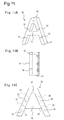
- Patent Document 1 describes, as shown in Fig. 11 , a planar illumination light source device 30 using a plurality of LEDs to make light displays of characters.
- the planar illumination light source device 30 is for making light displays of, for example, the alphabetic character A, and includes a housing 31 having a shape of the character A, a plurality of LEDs 32 spaced apart from each other by a predetermined distance in the housing, a light reflection plate 34 covering an opening of the housing, and a light diffusion plate 35 disposed opposite to and apart from the light reflection plate by a predetermined distance.
- the plurality of LEDs 32 are divided by partitions 36 to be disposed in the housing.
- the light reflection plate 34 includes a center reflection part having high light reflectivity in a region corresponding to the periphery of the optical axis of each LED and outer reflection parts having lower light reflectivity as the distance from the center reflection part increases, thereby achieving substantially uniform dispersion of light emitted from the LEDs for illumination.
- the planar illumination light source device disclosed in Patent Document 1 can make a light display of, for example, the alphabetic character A, using a plurality of LEDs. In order to display the character A, however, it is required to produce a planar illumination light source device corresponding to the character. Hence, when light displays of characters other than the character A are intended to be made, a planar illumination light source device corresponding to each character is required. In other words, displaying various types of characters requires various planar illumination light source devices corresponding to the characters. The type and the number of various characters are, however varied depending on displayed characters. To address this, a wide variety of planar illumination light source devices are required.
- planar illumination light source devices It is not realistic to prepare the wide variety of planar illumination light source devices in advance and such a planar illumination light source device must be customized in each case depending on the need for the character to be displayed. In the customization, a device cannot be mass-produced because the device is produced after an order is received, resulting in low productivity and increased cost.
- the character display requires a planar illumination light source device corresponding to each character and hence, has problems in which the character display cannot be applied with respect to a wide variety of light displays, the number of processes for installation is large, and the degree of freedom of display is limited.
- the planar illumination light source device disclosed in Patent Document 1 is to make a light display of the character A.
- a planar illumination light source device corresponding to each character is required in a similar manner.
- the present inventors have studied how to solve the problems possessed by a related art planar illumination light source device. As a result, the present inventors have found that, because LEDs alone are common parts among parts constituting the device and other parts are different from each other in the illumination device for the character A, by dividing and segmenting the illumination device into parts having a common structure, that is, into at least one or more sets of light source units, a common set of light source units enables the interchange of parts. In the dividing and segmenting, when another character is divided and segmented into parts in a similar manner, the parts can be interchanged among other characters. The invention is achieved based on the findings.
- An object of the invention is to provide a light display method and a light display device capable of providing planar light displays of various types of characters such as kanji characters, katakana characters, alphabetic characters, numeric characters, graphics, and symbols, with increased degrees of freedom, by using a plurality of point light sources and making light source units interchangeable on a point light source basis.
- Another object of the invention is to provide a light display method and a light display device capable of providing planar light displays while reducing the number of point light sources by enlarging the planar illumination area of a point light source unit.
- Another object of the invention is to provide a light display device that achieves the objects, is easily assembled and inexpensive, and can be used for various types of characters.
- a light display method of the invention includes making light displays of various types of characters by employing a plurality of point light sources.
- each light display of the characters is made by dividing and segmenting the characters into at least one or more sets of light source units including at least one of the point light sources, having a common structure in each character or a plurality of different characters, and making illumination by light emitted from the point light source as planar illumination light.
- light displays of various types of characters are made by dividing and segmenting into light source units having a common structure.
- common light source units can be used to make light displays of various types of characters such as kanji characters, katakana characters, alphabetic characters, numeric characters, and graphics, with increased degrees of freedom.
- light displays of various types of characters such as kanji characters, katakana characters, alphabetic characters, numeric characters, graphics, and symbols are made by dividing and segmenting the characters into at least one or more sets of light source units having a common structure in each character or a plurality of different characters and making illumination as planar illumination light, thereby enabling light displays with increased degrees of freedom of display.
- the light source unit have a rectangular solid shape, a folded solid shape, or a curved shape, include a unit case having a bottom with the point light source and having an opening, and also include a light reflection plate covering the opening of the unit case and outputting light emitted from the point light source as planar illumination light, and that such light source units be used in combination to make light displays of the characters.
- light displays of various types of characters can be easily made; that is, light displays can be made with increased degrees of freedom of display.
- the light source unit be stored in a character case having an opening and the opening be covered with a light diffusion plate to make light displays of the characters.
- the light source unit is stored in the character case and covered with the light diffusion plate. Even when a point light source is used, light display can be therefore made by substantially uniform illumination light from the light diffusion plate.
- a light display device of the invention employs a plurality of point light sources to make light displays of various types of characters.
- each light display of the characters is made by dividing and segmenting the characters into at least one or more sets of light source units including at least one of the point light sources, having a common structure in each character or a plurality of different characters, and making illumination by light emitted from the point light source as planar illumination light.
- the light display device of the invention makes light displays by dividing and segmenting into light source units having a common structure.
- common light source units in various types of characters such as kanji characters, katakana characters, alphabetic characters, numeric characters, and graphics can be used to make light displays, with increased degrees of freedom.
- the light display device for various types of characters can make light displays by dividing and segmenting the characters into at least one or more sets of light source units having a common structure in each character, for example, a kanji character, a katakana character, an alphabetic character, a numeric character, a graphic, or a symbol or a plurality of different characters and making illumination as planar illumination light, thereby enabling light displays with increased degrees of freedom of display.
- the light source unit have a rectangular solid shape, a folded solid shape, or a curved shape as an overall shape and include a unit case having a bottom with the point light source and having an opening opposed to the bottom, and also include a light reflection plate covering the opening and outputting light emitted from the point light source as planar illumination light, and that such light source units be used in combination to make light displays of the characters.
- the light source units having a rectangular solid shape, a folded solid shape, or a curved shape are used in an appropriate combination, thereby enabling easy light displays of various types of characters; that is, enabling light displays with increased degrees of freedom of display.
- the light source units be each stored in the character case, and the opening be covered with a light diffusion plate.
- the light display device of the invention can provide uniform illumination light from the light diffusion plate provided on the opening, thereby enabling light displays of characters with high quality.
- the light diffusion plate include a cover covering the opening of the character case and the opening be sealed up with the cover.
- the opening of the character case is sealed up with the cover.
- Such a structure prevents the entry of undesired substances such as insects and dusts into the light display device, thereby preventing the deterioration of illumination quality.
- waterproof sealing can make the light display device waterproof.
- the light reflection plate be apart from the point light source by a predetermined distance and include a center reflection part having high light reflectivity and low light transmittance in a predetermined region of which center is the optical axis of the point light source and an outer reflection part having a gradually reduced light reflectivity and an increased light transmittance as the distance from the periphery of the center reflection part increases.
- the light display device of the invention even when a point light source having strong directivity is used, substantially uniform illumination light can be emitted from the light reflection plate.
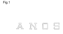
- Fig. 1 is a plan view of character examples for light displays by the light display method of an embodiment of the invention
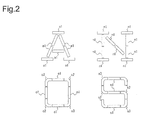
- Fig. 2 is a plan view of the characters in Fig. 1 divided and segmented into a plurality of light source units.
- Fig. 1 As the light display method of the embodiment of the invention, as shown in Fig. 1 , a method for light displays of alphabetic characters A, N, O, and S will be described.
- the characters in Fig. 1 are light display devices described later.
- the light display method is a method for light displays by dividing and segmenting the alphabetic characters A, N, O, and S into at least one or more sets of light source units having a common structure in each of the alphabetic characters or these characters.
- the light source unit includes an LED, a unit housing storing the LED and having an opening, and a light reflection plate covering the opening of the housing and outputting light emitted from the LED for planar illumination, as described later.
- each alphabetic character A, N, O, and S standard alphabetic character logotypes are changed and then divided and segmented into at least one set of light source unit having a common structure in each alphabetic character A, N, O, or S and these alphabetic characters so that the number of light source unit types is as small as possible.
- the uppercase alphabetic character A is divided and segmented into eight light source units a1 having a common structure as shown in Fig. 2 .
- Each light source unit a1 is a rectangular solid (hereinafter, called rectangular solid light source unit) having a predetermined length.
- the uppercase alphabetic character A includes the light source units a1 each having a common structure.
- the light source unit a1 can also be used for other uppercase alphabetic characters.
- the other uppercase alphabetic characters are divided and segmented in a similar manner.
- the uppercase alphabetic character N is divided and segmented into ten light source units n1
- the uppercase alphabetic character O is divided and segmented into four light source units o1, two light source units o2, and two light source units o3
- the uppercase alphabetic character S is divided and segmented into three light source units s1, four light source units s2, and two light source units s3.
- each of the light source units a1, n1, o1, and s1 in the uppercase alphabetic characters A, N, O, and S has a rectangular solid shape having a common structure
- each of the light source units o2 and s2 has a folded solid shape having a common structure
- each of the light source units o3 and s3 has a folded solid shape having a common structure.
- Fig. 3 shows the rectangular solid light source unit, Fig. 3A being a perspective view and Fig. 3B being an exploded perspective view.
- Fig. 4 is a typical optical directional curve of an LED.
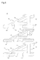
- Fig. 5 shows the folded solid light source units, Fig. 5A being a perspective view and an exploded perspective view of one folded solid light source unit and Fig. 5B being a perspective view and an exploded perspective view of the other folded solid light source unit.
- the rectangular solid light source unit 2 includes, as shown in Fig.
- the LED 3 is an LED including one light-emitting element or a plurality of assembled light-emitting elements and the LED to be used emits white light or another color light, for example, red, green, or blue.
- the LED 3 is fixed to a substrate 3a having a predetermined shape and is exposed into the case through a through-hole 4 1 in the bottom of the unit case 4.
- the LED 3 shows the highest luminance Lm at a beam spread angle of zero and has optical directional characteristics with an approximately spherical shape as a whole in which the luminance decreases as the angle increases, as shown in Fig. 4 .
- Another point light source such as a laser diode may be used in place of the LED.
- the unit case 4 includes, as shown in Fig. 3B , a rectangular solid box that includes a bottom 4a having a rectangular shape with a pair of long sides opposed to each other and a pair of short sides opposed to each other, side panels 4b to 4e having a predetermined height and standing from the periphery of the bottom, and an opening 4f at the top of each side panel, that is, on a face opposed to the bottom.
- the bottom 4a includes the through-hole 4 1 for exposing the LED 3 into the case.
- Inner walls of the box are processed to have high reflectivity.
- the whole of the unit case is preferably formed by an ultrafinely foamed reflection plate (trade name: MCPET). In the embodiment, one LED is disposed in the unit case 4, but a plurality of LEDs may be disposed.
- the light reflection plate 5 includes, as shown in Fig. 3 , a center reflection part 5a having a predetermined area at the center in the longitudinal direction and outer reflection parts 5b extending from the periphery of the center reflection part to the longitudinal direction and is formed by a reflection plate having a size covering the opening 4f of the unit case 4.
- the reflection plate is preferably formed by an ultrafinely foamed reflection plate (trade name: MCPET) having reflection faces on the front and back faces of the plate.
- the center reflection part 5a of the light reflection plate 5 is a region having a predetermined area and the center of the region is the optical axis of the LED 3.
- the region includes a region 5a1 that is close to the optical axis and has the highest light reflectivity and the lowest light transmittance, and a region 5a2 that is formed around the region 5a1 and has a slightly lower light reflectivity and a higher light transmittance than those of the region 5a1.
- the light reflectivity of the region 5a1 is appropriately designed by the selection of a light reflection plate material and the processes (for example, the formation of half-grooves and the adjustment of plate thickness) of the material, thereby efficiently using light.
- the region 5a2 includes micropores. The micropores may be replaced by slits, microgrooves, or the like.
- the outer reflection part 5b is a region in which light reflectivity decreases and in which light transmittance increases as the distance from the periphery of the center reflection part 5a increases.
- the outer reflection part 5b includes a reflection plate having through-holes with a predetermined aperture ratio, thereby adjusting the light reflectivity and the light transmittance.
- the rectangular solid light source unit 2 is assembled by installing the LED 3 onto the bottom of the unit case 4 and covering the opening 4f with the light reflection plate 5.
- the assembled rectangular solid light source unit 2 when the LED 3 is lighted, emitted light having the highest luminance is highly reflected by the center reflection part 5a, then is multiply reflected between the reflection face of the light reflection plate 5 and the inner reflection faces of the unit case 4, and is output from the outer reflection part 5b, thereby outputting substantially uniform illumination light from the surface of the light reflection plate.
- the center reflection part 5a has high reflectivity and low light transmittance. A bright spot therefore does not remain in the area and glare that is unpleasant brightness is not generated.
- the folded solid light source unit includes, as shown in Fig. 5 , two types of folded solid light source units 2A and 2B having folding directions different from each other.
- One folded solid light source unit 2A includes, as shown in Fig. 5A , one LED 3, a unit case 4A having the LED disposed on the bottom and also having an upper opening, and a light reflection plate 5A covering the opening of the case and outputting light emitted from the LED for planar illumination.
- the LED 3 is the same as the LED in the rectangular solid light source unit 2.
- the unit case 4A has a shape in which the unit case 4 having a rectangular solid shape is folded at approximately the center in a predetermined direction by a predetermined angle.
- the area of the opening 4f of the unit case 4 is substantially the same as the area of the opening of the unit case 4A.
- the unit case 4A includes a folding part at approximately the center and extending parts extended from both sides of the folding part and having a predetermined length, and is formed into an approximately arc shape as a whole.
- the folding angle is an angle suitable for the shape of a display character.
- the folding part includes a bottom in which a through-hole is formed for exposing the LED 3 into the case.
- Other structures are the same as those of the unit case 4.
- the light reflection plate 5A is, as shown in Fig. 5A , formed by a reflection plate having a size covering the opening of the unit case 4A and includes a center reflection part 5a having a predetermined area in a region corresponding to the folding part of the unit case and outer reflection parts 5b in regions corresponding to the extending parts. Other structures are the same as those of the light reflection plate 5.
- the center reflection part 5a has high reflectivity and low light transmittance. A bright spot therefore does not remain and glare that is unpleasant brightness is not generated.
- the other folded solid light source unit 2B has the same structure as that of the folded solid light source unit 2A except that the folding direction is different.
- the folded solid light source unit 2B includes an LED 3, a unit case 4B having the LED disposed on the bottom and also having an upper opening, and a light reflection plate 5B covering the opening of the case and outputting light emitted from the LED for planar illumination. With the folded solid light source unit 2B, substantially uniform illumination light is also output from the surface of the light reflection plate 5B.
- the rectangular solid light source unit and the folded solid light source units are used, but the light source unit is not limited to them, and light source units having various shapes such as a curved shape may be used depending on the character to be displayed.
- the light source units preferably have substantially the same opening area. This is because when opening areas are different from each other depending on light source units, light source units in which the type and the number of LEDs used as the light source are the same but the openings have varied areas provide varied illumination intensities; that is, a unit having a small opening area is relatively bright and a unit having a large opening area is relatively dark, resulting in non-uniform illumination intensity as a whole.
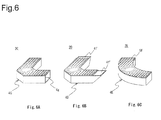
- FIG. 6 is a perspective view of the alternative examples of the folded solid light source unit of the embodiment. These alternative examples of the folded solid light source unit have a common structure to the structure of the folded solid light source unit 2A except some components, and hence, the common description will be left out. These alternative examples can be applied to the rectangular solid light source unit in a similar manner.
- Fig. 6A is a perspective view of an alternative example of the folded solid light source unit in which any of the side panels of the unit case is left out. In a folded solid light source unit 2C, any of the side panels of a unit case 4C is left out and a side opening 4g is provided.
- a clearance may be generated between some unit cases, or between a unit case and a character frame case 11 described later due to a character shape.
- any of the side panels adjacent to the clearance is left out to make the side opening 4g that transmits light from an LED, thereby suppressing the reduction in brightness in an area corresponding to the clearance on an illumination face.
- the side panel may be provided with an opening having a predetermined area and this can provide the same effect as the case in which a side panel is left out.
- Fig. 6B is a perspective view of an alternative example of the folded solid light source unit in which any of the side panels of the folded solid light source unit in Fig. 5 is tilted.
- a folded solid light source unit 2D any of the side walls of a unit case 4D is tilted at a predetermined angle (for example, 135°) with respect to the bottom.
- the tilt angle is preferably more than 90° and about 150° at most with respect to the bottom.
- the opening of the unit case can be enlarged and LED light can be efficiently output toward the opening using the slope.
- any of the side panels is tilted but all the side panels may be tilted from the periphery of the bottom to the outside at a predetermined angle.
- a light reflection plate 5D is not changed and the enlarged area in an opening 4f of the unit case is not covered with the light reflection plate to make an end opening 4f'.
- illumination intensity may be reduced in the end area apart from an LED.
- the light reflection plate 5D may have an enlarged area corresponding to an enlarged opening of the unit case to completely cover the opening 4f of the unit case.
- Fig. 6C is a perspective view of an alternative example in which the shape of the folded solid light source unit in Fig. 5 is changed.
- a curved light source unit 2E has an arc shape by changing the shape of the folded solid light source unit 2A.
- a unit case 4E has an LED at the bottom center and is formed into an arc shape as a whole. The length of the arc is designed so as to fit the shape of a display character. Other components are the same as those of the unit case 4A.
- a light reflection plate 5E is formed by a reflection plate having a size covering the opening of the unit case 4E and includes a center reflection part 5a having a predetermined area in a region corresponding to the LED disposed in the unit case and outer reflection parts 5b in regions corresponding to the extending parts. Other components are the same as those of the light reflection plates 5 and 5A. With the folded solid light source unit 2E, substantially uniform illumination light is also output from the surface of the light reflection plate 5A. As described above, the shape of the light source unit is not limited to them and can be changed corresponding to the shape of the character to be displayed.
- characters are divided and segmented into at least one or more sets of light source units having a common structure in each of uppercase alphabetic characters A, N, O, and S and these characters.
- the light source units are interchangeable, that is, unit parts are common, thereby making light displays of the alphabetic characters A, N, O, and S using a few types of parts.
- various characters except the alphabetic characters A, N, O, and S for example, kanji characters, katakana characters, numeric characters, graphics, and symbols can also be made into light displays.
- light displays of various types of characters can be made with increased degrees of freedom of display.
- preparation and management of parts become easier and the parts can be prepared at low cost because the unit parts are interchangeable.
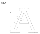
- Fig. 7 is a plan view of the light display device of the embodiment of the invention.
- Fig. 8 is an exploded perspective view of the light display device in Fig. 7 .
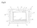
- Fig. 9 is a sectional view taken along the line IX-IX in Fig. 7 .
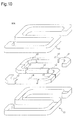
- Fig. 10 is an exploded perspective view of another light display device.
- Figs. 7 and 8 show a light display device to make a light display of an uppercase alphabetic character A.
- the light display device 10 includes, as shown in Fig. 8 , a character frame case 11 having a character A shape, a plurality of light source units a1 to be stored in the character frame case, and a cap 12 for covering an opening of the character frame case.
- the cap 12 is expressed as a cover in the claims.
- the character frame case 11 is formed by a frame that includes a bottom plate 11a having a character A shape, side panels 11b having a predetermined height and standing from the bottom plate, and an opening 11c being an open face opposed to the bottom plate and being at the top of each side panel and that includes a space having a size capable of storing therein the plurality of light source units a1.
- the frame is formed by a molded body made of, for example, a synthetic resin or a metal plate.
- the character frame case 11 is a changed standard logotype so as to store the plurality of light source units a1 having a common structure.
- inner walls are preferably reflection faces.
- the character frame case 11 includes the bottom plate 11a having a fixing part 11 1 for fixing the light source unit a1 and having an attaching part for attaching the case onto, for example, an exterior wall of a building.
- the fixing part 11 1 is provided on an inner wall of the bottom plate 11a and the attaching part is provided on a back side of the bottom plate 11a.
- the cap 12 includes a ceiling plate 12a having a character A shape, side panels 12b having a predetermined length and hanging from the ceiling plate, and an opening 12c being an open face opposed to the ceiling plate and being at the top of each side panel.
- the opening is formed to have a size to close the opening 11c of the character frame case 11.
- the cap 12 is integrally molded using a light diffusion member, for example, a synthetic resin material such as an acrylic resin.
- the whole cap 12 is formed by a light diffusion member, but the ceiling plate 12a may be formed by a light diffusion member.
- the plurality of light source units a1 are firstly disposed in the character frame case 11.
- Each light source unit a1 is fixed to the bottom plate 11a of the character frame case 11 with the fixing part 11 1 . Then, the opening of the character frame case 11 is covered with the cap 12, which is then fixed.
- each light source unit a1 when the LED 3 in each light source unit a1 is lighted, a large part of emitted light in every light source unit having the highest luminance is reflected by the center reflection part 5a, then is multiply reflected between the reflection face of the light reflection plate 5 and the inner reflection faces of the unit case 4, and is output from the outer reflection part 5b, thereby outputting substantially uniform illumination light from the surface of the light reflection plate.
- the center reflection part 5a has high light reflectivity and low light transmittance. A bright spot therefore does not remain in the area and bright glare is not generated.
- each light source unit a1 is covered with the cap 12 and the cap 12 is a light diffusion plate.
- uniform illumination light is output from the surface of the diffusion plate, thereby making the light display of the uppercase alphabetic character A.
- the light source units are interchangeable in the light display device of the embodiment, preparation and management of parts become easier and the parts can be prepared at low cost.
- the character frame case 11 is sealed up with the cap 12, thereby preventing the entry of undesired substances such as insects and dust into the light display device.
- waterproof sealing can make the light display device waterproof.
- the light display device 10A includes a character frame case 13 having a character S shape, a plurality of light source units s1 to s3 to be stored in the character frame case, and a cap 14 for covering an opening of the character frame case.
- the character frame case 13 is formed by a frame that includes a bottom plate having a character S shape, side panels having a predetermined height and standing from the bottom plate, and an opening being an open face opposed to the bottom plate and being at the top of each side panel and that includes a space having a size capable of storing the plurality of light source units s1 to s3.
- the frame is formed by a molded body made of, for example, a synthetic resin or a metal plate.
- the character frame case 13 is a changed standard logotype so as to store the plurality of light source units s1 to s3 each having a common structure.
- inner walls are preferably reflection faces.
- the plurality of light source units s1 to s3 employ the rectangular solid light source unit 2 and the folded solid light source units 2A and 2B shown in Figs. 3 and 5 .
- the cap 14 includes a ceiling plate having a character S shape, side panels having a predetermined length and hanging from the ceiling plate, and an opening being an open face opposed to the ceiling plate and being at the top of each side panel. The opening is formed to have a size to close the opening of the character frame case 13.
- the cap 14 is integrally molded using a light diffusion member, for example, a synthetic resin material such as an acrylic resin.
- the whole cap 14 is formed by a light diffusion member, but the ceiling plate 12a may be formed by a light diffusion member.
- the light display device 10A provides the same action and effect as the light display device 10.
- the rectangular solid light source unit and the folded solid light source units are used, but the light source unit is not limited to them, and light source units having various shapes such as a curved shape may be used depending on the character to be displayed.
- these light source units preferably have substantially the same opening area. This is because when opening areas are different from each other depending on light source units, light source units in which the type and the number of LEDs used as the light source are the same but the openings have varied areas, provide varied illumination intensities, resulting in non-uniform illumination intensity as the whole of the light display device.
Landscapes
- Physics & Mathematics (AREA)
- General Physics & Mathematics (AREA)
- Engineering & Computer Science (AREA)
- Theoretical Computer Science (AREA)
- Illuminated Signs And Luminous Advertising (AREA)
- Planar Illumination Modules (AREA)
- Non-Portable Lighting Devices Or Systems Thereof (AREA)
Applications Claiming Priority (2)
| Application Number | Priority Date | Filing Date | Title |
|---|---|---|---|
| JP2010095277A JP2011227197A (ja) | 2010-04-16 | 2010-04-16 | 照明表示方法及び照明表示装置 |
| PCT/JP2011/059444 WO2011129451A1 (fr) | 2010-04-16 | 2011-04-15 | Procédé d'affichage lumineux et dispositif d'affichage lumineux |
Publications (2)
| Publication Number | Publication Date |
|---|---|
| EP2560154A1 true EP2560154A1 (fr) | 2013-02-20 |
| EP2560154A4 EP2560154A4 (fr) | 2013-10-23 |
Family
ID=44798818
Family Applications (1)
| Application Number | Title | Priority Date | Filing Date |
|---|---|---|---|
| EP11768972.9A Withdrawn EP2560154A4 (fr) | 2010-04-16 | 2011-04-15 | Procédé d'affichage lumineux et dispositif d'affichage lumineux |
Country Status (6)
| Country | Link |
|---|---|
| US (1) | US20130039061A1 (fr) |
| EP (1) | EP2560154A4 (fr) |
| JP (1) | JP2011227197A (fr) |
| KR (1) | KR20130062265A (fr) |
| CN (1) | CN102844805A (fr) |
| WO (1) | WO2011129451A1 (fr) |
Cited By (1)
| Publication number | Priority date | Publication date | Assignee | Title |
|---|---|---|---|---|
| EP2562473A4 (fr) * | 2010-04-23 | 2015-02-18 | Opto Design Inc | Appareil d'éclairage de surface et dispositif associé |
Families Citing this family (4)
| Publication number | Priority date | Publication date | Assignee | Title |
|---|---|---|---|---|
| WO2014050848A1 (fr) * | 2012-09-27 | 2014-04-03 | コニカミノルタ株式会社 | Panneau d'affichage d'illustration |
| US9827483B2 (en) | 2014-08-01 | 2017-11-28 | Smart Billiard Lighting LLC | Billiard table lighting and game play monitor |
| EP3174612B1 (fr) | 2014-08-01 | 2019-09-04 | Smart Billiard Lighting LLC | Éclairage de table de billard et surveillance de partie de jeu |
| USD835652S1 (en) | 2015-12-10 | 2018-12-11 | Smart Billiard Lighting LLC | Display screen with transitional graphical user interface of a billiard game |
Family Cites Families (7)
| Publication number | Priority date | Publication date | Assignee | Title |
|---|---|---|---|---|
| JPS63246787A (ja) * | 1987-04-01 | 1988-10-13 | 有限会社 ホクシン工業 | 文字表示具 |
| JPS6429686U (fr) * | 1987-08-18 | 1989-02-22 | ||
| US6566824B2 (en) * | 2001-10-16 | 2003-05-20 | Teledyne Lighting And Display Products, Inc. | Flexible lighting segment |
| JP4280283B2 (ja) * | 2006-01-27 | 2009-06-17 | 株式会社オプトデザイン | 面照明光源装置及びこれを用いた面照明装置 |
| US7937865B2 (en) * | 2006-03-08 | 2011-05-10 | Intematix Corporation | Light emitting sign and display surface therefor |
| JP5139314B2 (ja) * | 2006-10-27 | 2013-02-06 | 森山産業株式会社 | 表示装置 |
| JP3141533U (ja) * | 2008-02-25 | 2008-05-08 | 株式会社ユキ・エンター・プライズ | 導光板による自発光表示物 |
-
2010
- 2010-04-16 JP JP2010095277A patent/JP2011227197A/ja active Pending
-
2011
- 2011-04-15 WO PCT/JP2011/059444 patent/WO2011129451A1/fr not_active Ceased
- 2011-04-15 US US13/641,391 patent/US20130039061A1/en not_active Abandoned
- 2011-04-15 CN CN2011800190903A patent/CN102844805A/zh active Pending
- 2011-04-15 KR KR1020127026807A patent/KR20130062265A/ko not_active Withdrawn
- 2011-04-15 EP EP11768972.9A patent/EP2560154A4/fr not_active Withdrawn
Cited By (1)
| Publication number | Priority date | Publication date | Assignee | Title |
|---|---|---|---|---|
| EP2562473A4 (fr) * | 2010-04-23 | 2015-02-18 | Opto Design Inc | Appareil d'éclairage de surface et dispositif associé |
Also Published As
| Publication number | Publication date |
|---|---|
| EP2560154A4 (fr) | 2013-10-23 |
| US20130039061A1 (en) | 2013-02-14 |
| WO2011129451A1 (fr) | 2011-10-20 |
| JP2011227197A (ja) | 2011-11-10 |
| KR20130062265A (ko) | 2013-06-12 |
| CN102844805A (zh) | 2012-12-26 |
Similar Documents
| Publication | Publication Date | Title |
|---|---|---|
| EP2562473B1 (fr) | Appareil d'éclairage de surface et dispositif associé | |
| US20130003354A1 (en) | Light Directing Sign Substrate | |
| US20130039061A1 (en) | Light display method and light display device | |
| JP2010528444A (ja) | 照明システム、照明器具及びバックライティングユニット | |
| JP2013149589A (ja) | 直管形ledランプ | |
| EP2479480A1 (fr) | Dispositif de source lumineuse et dispositif d'éclairage de surfaces utilisant un tel dispositif de source lumineuse | |
| JP5417568B2 (ja) | 面照明光源装置及びその面照明光源装置を複数配置した面照明装置 | |
| EP2175194A1 (fr) | Dispositif d'éclairage et son abat-jour de réflexion de la lumière | |
| JP2011034674A (ja) | 面状光源および電飾看板 | |
| JPH11274572A (ja) | Led表示素子および表示装置 | |
| JP2009067098A (ja) | 照明装置 | |
| US9062848B2 (en) | Light source device and illumination device including the light source device | |
| JP2012182117A (ja) | 管型照明器具、管型照明器具用筐体及び両面内照式看板装置 | |
| EP2474776A1 (fr) | Dispositif de source de lumière, dispositif d'éclairage et dispositif d'affichage | |
| JP2007207752A (ja) | 面状光源および電飾看板 | |
| CN113574312A (zh) | 发光设备 | |
| JP2009252447A (ja) | 導光器、照明装置、表示装置 | |
| JP2006216821A (ja) | 発光ダイオード | |
| JP2009032525A (ja) | 面照明ユニット、面照明光源装置、および面照明装置 | |
| JP2010113998A (ja) | 導光部材、光源装置及び携帯端末装置 | |
| CN222950930U (zh) | Led灯具 | |
| CN115135927A (zh) | 用于发光面板的发光器件 | |
| WO2011033551A1 (fr) | Appareil d'éclairage | |
| EP2915198B1 (fr) | Module électroluminescent, et dispositif d'éclairage et boîtier lumineux comprenant le module électroluminescent | |
| JP2001092397A (ja) | 光源を内蔵する壁面用の看板文字または図形 |
Legal Events
| Date | Code | Title | Description |
|---|---|---|---|
| PUAI | Public reference made under article 153(3) epc to a published international application that has entered the european phase |
Free format text: ORIGINAL CODE: 0009012 |
|
| 17P | Request for examination filed |
Effective date: 20121015 |
|
| AK | Designated contracting states |
Kind code of ref document: A1 Designated state(s): AL AT BE BG CH CY CZ DE DK EE ES FI FR GB GR HR HU IE IS IT LI LT LU LV MC MK MT NL NO PL PT RO RS SE SI SK SM TR |
|
| DAX | Request for extension of the european patent (deleted) | ||
| A4 | Supplementary search report drawn up and despatched |
Effective date: 20130919 |
|
| RIC1 | Information provided on ipc code assigned before grant |
Ipc: G09F 13/20 20060101AFI20130913BHEP Ipc: F21Y 101/02 20060101ALI20130913BHEP Ipc: F21S 2/00 20060101ALI20130913BHEP |
|
| STAA | Information on the status of an ep patent application or granted ep patent |
Free format text: STATUS: THE APPLICATION IS DEEMED TO BE WITHDRAWN |
|
| 18D | Application deemed to be withdrawn |
Effective date: 20140423 |