EP2560321B1 - Ethernet-multicast-verfahren und -vorrichtung - Google Patents
Ethernet-multicast-verfahren und -vorrichtung Download PDFInfo
- Publication number
- EP2560321B1 EP2560321B1 EP11806235.5A EP11806235A EP2560321B1 EP 2560321 B1 EP2560321 B1 EP 2560321B1 EP 11806235 A EP11806235 A EP 11806235A EP 2560321 B1 EP2560321 B1 EP 2560321B1
- Authority
- EP
- European Patent Office
- Prior art keywords
- multicast
- root node
- management device
- group
- destination
- Prior art date
- Legal status (The legal status is an assumption and is not a legal conclusion. Google has not performed a legal analysis and makes no representation as to the accuracy of the status listed.)
- Active
Links
Images



Classifications
-
- H—ELECTRICITY
- H04—ELECTRIC COMMUNICATION TECHNIQUE
- H04L—TRANSMISSION OF DIGITAL INFORMATION, e.g. TELEGRAPHIC COMMUNICATION
- H04L12/00—Data switching networks
- H04L12/54—Store-and-forward switching systems
- H04L12/56—Packet switching systems
-
- H—ELECTRICITY
- H04—ELECTRIC COMMUNICATION TECHNIQUE
- H04L—TRANSMISSION OF DIGITAL INFORMATION, e.g. TELEGRAPHIC COMMUNICATION
- H04L12/00—Data switching networks
- H04L12/28—Data switching networks characterised by path configuration, e.g. LAN [Local Area Networks] or WAN [Wide Area Networks]
- H04L12/40—Bus networks
- H04L12/407—Bus networks with decentralised control
- H04L12/413—Bus networks with decentralised control with random access, e.g. carrier-sense multiple-access with collision detection [CSMA-CD]
-
- H—ELECTRICITY
- H04—ELECTRIC COMMUNICATION TECHNIQUE
- H04L—TRANSMISSION OF DIGITAL INFORMATION, e.g. TELEGRAPHIC COMMUNICATION
- H04L12/00—Data switching networks
- H04L12/02—Details
- H04L12/16—Arrangements for providing special services to substations
- H04L12/18—Arrangements for providing special services to substations for broadcast or conference, e.g. multicast
- H04L12/185—Arrangements for providing special services to substations for broadcast or conference, e.g. multicast with management of multicast group membership
-
- H—ELECTRICITY
- H04—ELECTRIC COMMUNICATION TECHNIQUE
- H04L—TRANSMISSION OF DIGITAL INFORMATION, e.g. TELEGRAPHIC COMMUNICATION
- H04L12/00—Data switching networks
- H04L12/28—Data switching networks characterised by path configuration, e.g. LAN [Local Area Networks] or WAN [Wide Area Networks]
- H04L12/40—Bus networks
- H04L12/40006—Architecture of a communication node
- H04L12/40013—Details regarding a bus controller
-
- H—ELECTRICITY
- H04—ELECTRIC COMMUNICATION TECHNIQUE
- H04L—TRANSMISSION OF DIGITAL INFORMATION, e.g. TELEGRAPHIC COMMUNICATION
- H04L45/00—Routing or path finding of packets in data switching networks
- H04L45/16—Multipoint routing
Definitions
- the present invention relates generally to the communications technology field, and in particular to an Ethernet multicast method and device.
- Ethernet switches are low-priced and maintained and configured at low cost, a lot of large-scaled networks such as Data Centers and Metropolitan Area Networks (MANs) adopt a large amount of Ethernet switches to perform networking.
- MANs Metropolitan Area Networks
- the distribution of data in a multicasting manner is advantageous of network construction at low cost, high data distribution efficiency, and the like.
- the scale of traditional Ethernet networks is restricted due to their poor expandability, the advantage of multicasting in the Ethernet networks cannot be exhibited.
- SEATTLE A scalable Ethernet architecture for large enterprises
- SIGCOMM'08, August 17-22,2008, 17 August 2008(2008-8-17) pages 3-14, XP055048610, Seattle, Washington, USA
- SEATTLE uses a DHT (Distributed Hash Table) routing addressing mechanism to realize the expansion of the Ethernet networks.
- the host uses a Directory Service to release and maintain a mapping relationship between a MAC address and the current location, and forwards data through this mapping relationship. For example, when a host a whose MAC address is MACa arrives at its access switch Sa, this switch must release in the Directory Service a mapping relationship between the MAC of the host a and the location thereof.
- the host b forwards the data to an access switch Sb
- the switch ra In order to limit the number of data packets passing through the parser, the switch ra also notifies the switch Sb that the current location of the host a is Sa. The switch Sb then stores in a buffer related information that the current location of the host a is Sa. When the data packets are forwarded subsequently, the switch Sb can forward the data packets by searching for the information in the buffer, thereby improving the data forwarding efficiency.
- a host searches for a MAC address corresponding to an IP address by means of ARP in the traditional Ethernet networks, but SEATTLE avoids ARP flooding in the traditional Ethernet networks and expands the ARP, so that the ARP returns both the MAC address of the host and information of the switch connected to the host (the information reflects the location of the host). Since the location information of the host is sensed, the data packets can forward ARP requests by selecting the shortest path.
- the inventors select a multicast root node, randomly map a multicast group to a switch using a hash function, and enable the switch to act as the multicast root node, but this manner of constructing a multicast tree does not take a network topology into consideration, as a result of which the selected multicast tree root node may be far from all the receiving hosts, thereby reducing the Ethernet multicast performance.
- DONG-LIM LEE ET AL "RP reselection scheme for real-time applications in delay-constrained multicast networks", Proceedings of IEEE international conference on communications -28 April 2 - 2 May 2002, New York, NY, USA, IEEE, Piscataway, NJ, USA, vol.
- the embodiments of the present invention provide an Ethernet multicast method and device, which improve the capability of distributing multicast data in the Ethernet network.
- An Ethernet multicast method comprising:
- a multicast management device comprising:
- a communication device comprising:
- a multicast management device is determined in accordance with a multicast MAC address of the destination multicast group, a request carrying the multicast MAC address of the destination multicast group is transmitted to the multicast management device, the multicast management device selects, according to the request, a switch satisfying a particular optimization condition as a multicast root node corresponding to the multicast MAC address of the destination multicast group when it is determined that the multicast MAC address of the destination multicast group does not have the corresponding multicast root node.
- the multicast root node is selected, an identification of the multicast root node is transmitted to the host/multicast source.
- the multicast management device when selecting the multicast root node, selects the switch satisfying a particular optimization condition such as a switch with a closest/closer distance to the host/multicast source, as the multicast root node.
- a particular optimization condition such as a switch with a closest/closer distance to the host/multicast source
- the embodiments of the present invention can reduce the circumstances under which the selected multicast root node is far from all the receiving hosts, thereby improving the capability of multicast data transmission in the Ethernet networks.
- the embodiment of the present invention is applied in a scenario in which a layered network topology is supposed to be used, wherein all multicast management devices in the same Ethernet network logically constitute a DHT loop and they jointly manage multicast groups within the entire Ethernet.
- Each multicast management device under the loop manages a group of switches, and these switches and multicast management devices can be either directly connected through links, or interconnected through other devices such as switches.
- the practical application scenario is not limited to the layered network.
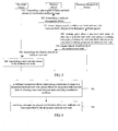
- the embodiment of the present invention provides an Ethernet multicast method, comprising the following steps:
- step 1001 if a request from the host is received in step 1001, the identification of the multicast root node will be transmitted to the host in step 1003, while if a request from the multicast source is received in step 1001, the identification of the multicast root node will be transmitted to the multicast source in step 1003.
- the embodiment of the present invention further provides another Ethernet multicast method, comprising the following steps:
- the host may transmit a join message to the multicast root node, the join message is forwarded to the multicast root node in accordance with a protocol of the shortest path, and all switches on the shortest forwarding path that have received the join message will automatically generate, in their forwarding tables, a table entry containing the multicast group and the multicast root node, thereby constructing a multicast tree branch from the host to the multicast root node.
- the multicast source may transmit a multicast data stream to the multicast root node in accordance with the shortest forwarding path, thereby determining the construction of a multicast tree branch from the multicast source to the multicast root node in accordance with the shortest forwarding path.
- the multicast management device when selecting the multicast root node, selects the switch satisfying a particular optimization condition such as a switch with a closest/closer distance to the host/multicast source, as the multicast root node.
- a particular optimization condition such as a switch with a closest/closer distance to the host/multicast source
- the selection and management of the multicast root node are performed by the multicast management device, so that the multicast management function and the multicast root node are independent of each other within the Ethernet, thereby improving the flexibility and facileness of multicast management.
- a request can be transmitted in this step, through the host/multicast source, to a Direction Switch DS connected directly thereto, and the DS performs a hashing operation to find the corresponding multicast management device.
- the host/multicast source itself performs a hashing operation to find the corresponding multicast management device.
- the request may be either a request for joining a multicast group, or a request for obtaining an identification of a multicast root node corresponding to the destination multicast group.
- the identification may be an IP address or a MAC address of the multicast root node, or a character identifying the multicast root node such as an ID of the multicast root node.
- the multicast management device selects, according to the request, a switch satisfying a particular optimization condition as the multicast root node corresponding to the destination multicast group by means of an optimization algorithm, when it is determined that the multicast MAC address of the destination multicast group does not have the corresponding multicast root node. For example, it is possible to select, among the switches managed by the multicast management device, a switch with the lowest load, or to select, with reference to a geographical location of the host/multicast source, a host closest to the (or all) host(s)/multicast source(s) as a root node of the destination multicast group.
- the multicast management device stores a mapping relationship between the multicast MAC address of the destination multicast group and the selected multicast root node.
- the mapping relationship is stored in a mapping table, and when other hosts/multicast sources also make a request for joining the multicast group, a query about the multicast root node corresponding to the multicast MAC address of the destination multicast group is made in the mapping relationship table in accordance with the request received in step 103, an identification of the multicast root node queried about is transmitted to the host/multicast source.
- the multicast root node corresponding to the multicast MAC address of the multicast group can be directly returned to the corresponding host/multicast source, without the necessity of performing reselection of a multicast root node, thereby improving the efficiency of managing the multicast root node.
- the multicast management device transmits the identification of the multicast root node corresponding to the multicast MAC address of the destination multicast group to the host/multicast source.
- the host/multicast source may transmit the corresponding data to the multicast root node after receiving the identification of the multicast root node.
- step 101 data communication in steps 102 to 107 will be performed between the multicast management device and the host.
- step 101 is described from the multicast source side, data communication in steps 102 to 107 will be performed between the multicast management device and the multicast source.
- an independent multicast management device selects the switch satisfying a particular optimization condition such as a switch with a closest/closer distance to the host, as the multicast root node, so that it is possible to decrease the multicast capability reduction due to the selected multicast root node with a farther distance to the location of the host in the conventional art, thereby improving the multicast capability.
- a particular optimization condition such as a switch with a closest/closer distance to the host
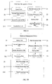
- the multicast management device ra may select a switch satisfying a particular optimization condition among the switches under its management by means of a root node selection algorithm, with reference to topology information of the network and a geographical location of the host. For example, it selects a switch with the lowest load to serve as a root node of the destination multicast group G, or selects a switch with the closest distance to the host, and stores a mapping relationship between the multicast MAC address of the destination multicast group and the selected multicast root node, and for instance, the mapping relationship may be stored as (MulticastMACAddress, RP), wherein MulticastMACAddress represents the multicast MAC address of the destination multicast group G, and RP represents an identification of the selected multicast root node, which may be an IP address, a MAC address or an identifying character such as an ID.
- a root node selection algorithm For example, it selects a switch with the lowest load to serve as a root node of the destination multicast group G, or selects a switch with the closest distance to
- the multicast management device ra forwards the identification of the selected multicast root node to the direction switch Sa.
- the direction switch Sa transmits the identification of the multicast root node to the host a, but during specific implementation, this step may also be absent in this solution.
- the direction switch Sa after receiving the identification of the multicast root node, transmits a join message toward a multicast root node RP direction corresponding to the multicast group G hop by hop, the path through which the message is transmitted follows a shortest path preference algorithm, thereby constructing a branch of a multicast forwarding tree SPT (Shortest Path Tree); all switches on the SPT generate a table entry containing the destination multicast group and the multicast root node, which may be represented as (RP, MulticastMACAddress, ports), wherein ports represent forwarding ports of the switch.
- SPT Shortest Path Tree
- All switches on the SPT generate a table entry containing the destination multicast group and the multicast root node, which may be represented as (RP, MulticastMACAddress, ports), wherein ports represent forwarding ports of the switch.
- the above-mentioned generated SPT takes the multicast root node RP as root, and the direction switch DS as leaf.
- the host transmits the request for joining the destination multicast group, and meanwhile, the host does not sense information of the multicast root node, which is however obtained by the direction switch Sa, and makes the request for joining the destination multicast group to the multicast root node, and constructs the multicast tree, etc.
- the host transmits the request for joining the destination multicast group, and meanwhile, the host does not sense information of the multicast root node, which is however obtained by the direction switch Sa, and makes the request for joining the destination multicast group to the multicast root node, and constructs the multicast tree, etc.
- an alternative solution is as follows:
- step 202 the direction switch forwards the request for obtaining the multicast root node
- step 205 the direction switch transmits the multicast root node to the host;
- step 206 the host, after receiving the identification of the multicast root node, transmits to the direction switch Sa the request for joining the destination multicast group, such as a message similar to IGMP join, and the direction switch Sa transmits to the multicast root node the request for joining the destination multicast group. Meanwhile, the host may carry the identification of the multicast root node in the request for joining the destination multicast group transmitted to the direction switch Sa, or may not carry the identification of the multicast root node. If information of the multicast root node is not carried in the join request, the information of the multicast root node needs to be stored through the direction switch Sa in step 5.
- the direction switch determines the multicast management device by performing a hashing operation
- the second feasible solution is as follows: the host itself determines the multicast management device by performing a hashing operation, an identification of the multicast management device is carried in the request transmitted to the direction switch, and the direction switch forwards the request from the host to the multicast management device.
- the multicast MAC address of the destination multicast group is used as an argument, and an identification of the multicast management device is obtained by calculation using a preset hash function, that is, the multicast management device is found by a hashing operation (the hashing operation obtains the identification of the multicast management device by hashing the multicast MAC address, and the identification may be an IP address or a MAC address or an identifying character such as an ID), and a message requesting for obtaining an address of the multicast root node RP is transmitted to the multicast management device.
- a hashing operation obtains the identification of the multicast management device by hashing the multicast MAC address, and the identification may be an IP address or a MAC address or an identifying character such as an ID
- the multicast management device selects, according to the request, a switch satisfying a particular optimization condition as a multicast root node corresponding to the multicast MAC address of the destination multicast group when it is determined that the multicast MAC address of the destination multicast group does not have the corresponding multicast root node.
- the multicast management device may query about the multicast root node corresponding to the multicast MAC address of the destination multicast group in the mapping relationship table according to the request, and if the multicast root node corresponding to the multicast MAC address of the destination multicast group has been stored in the mapping relationship table, it is only necessary to transmit an identification of the queried multicast root node to the multicast source.
- the multicast management device selects a switch by means of an algorithm. For example, it selects a switch with the lowest load to serve as a root node of the destination multicast group G, or selects a switch with the closest distance to the multicast source, and stores a mapping relationship between the multicast MAC address of the destination multicast group and the selected multicast root node, and for instance, the mapping relationship may be stored as (MulticastMACAddress, RP), wherein MulticastMACAddress represents the multicast MAC address of the destination multicast group G, and RP represents the selected multicast root node.
- the multicast management device forwards an identification of the selected multicast root node to the direction switch.
- the direction switch transmits the identification of the multicast root node to the multicast source.
- the multicast source after receiving the identification of the multicast root node, transmits a multicast data stream to the direction switch, the direction switch selects a shortest path to the multicast root node RP, and forwards the data stream from the multicast source by unicast, thereby completing construction of a distribution tree from the multicast source to the multicast root node.
- the direction switch determines the multicast management device by performing a hashing operation, and during practical application, alternatively, the multicast source itself determines the multicast management device by performing a hashing operation, an identification of the multicast management device is carried in the request transmitted to the direction switch, and then the direction switch forwards the request from the multicast source to the multicast management device.
- the multicast management device when selecting the multicast root node, selects a switch satisfying a particular optimization condition such as a switch with a closer distance to the host/multicast source, as the multicast root node, with reference to topology information of the network and a geographical location of the host/multicast source.
- a particular optimization condition such as a switch with a closer distance to the host/multicast source, as the multicast root node, with reference to topology information of the network and a geographical location of the host/multicast source.
- the embodiment of the present invention further provides an optimized technical solution, that is, at a different time, in the embodiment of the present invention, the multicast management device may trigger reselection of a multicast root node and adjust the existing multicast tree, so that it is possible to construct a multicast distribution tree more reasonably, thereby further improving the capability of multicast data distribution within the Ethernet.
- the multicast management device may trigger reselection of a multicast root node and adjust the existing multicast tree, so that it is possible to construct a multicast distribution tree more reasonably, thereby further improving the capability of multicast data distribution within the Ethernet.
- a detailed description of reselection of the multicast root node is given below.
- an Ethernet multicast method comprising the following steps:
- an identification of the new multicast root node is transmitted to the multicast management device.
- the multicast management device receives the identification of the new multicast root node transmitted by the designated multicast root node.
- multicast management device itself triggers reselection of the multicast root node, and the multicast management device itself selects the new multicast root node satisfying the reselection condition.
- the reselection of a root node is triggered based on configuration information, changes in network conditions are detected, reselection of the root node is triggered based on the optimization algorithm, etc.
- the specific triggering factors are not only limited to those mentioned above.
- the multicast management device after obtaining the identification of the new multicast root node, performs construction of a new multicast tree and removal of an old multicast tree, and further, the method further comprises the following steps:
- an alternative substitute solution is as follows: the direction switch transmits the request to the host, and the host after receiving the request initiates a request to the direction switch and the direction switch transmits the join message to the new multicast root node RP, thereby constructing the new multicast tree.
- the new multicast root node enables the traffic within the entire network to be most optimum, or the new multicast root node has a closest average location to all hosts within the belonging group. Then a new multicast tree including the new multicast root node is constructed, and for example, the root node of the new multicast tree has the closest average location to all hosts within the belonging group, so that the capability of multicast data distribution within the Ethernet can be further improved.
- a multicast group is hashed to a specific CoreSwitch using a hash function, the CoreSwitch serves as a multicast root node, and data packets are transmitted to the CoreSwitch and distributed.
- this method fixedly selects the CoreSwitch in a tree-like topology structure as the multicast root node, which tends to cause the multicast root node far from all receiving hosts.
- the embodiment of the present invention can perform selection and adjustment of the multicast root node with reference to network topology information and a geographical location of the host, which can optimize the capability of transmission between the multicast root node and all the receiving hosts, thereby improving the multicast performance.
- the invention of the present invention provides a communication device, which as shown in FIG. 6 comprises: a determining unit 11, a transmission unit 12 and a reception unit 13.
- the determining unit 11 is used to determine a multicast management device in accordance with a multicast MAC address of the destination multicast group; the transmission unit 12 is used to transmit, to the multicast management device, a request carrying the multicast MAC address of the destination multicast group.
- the multicast management device returns an identification of a corresponding multicast root node in accordance with the multicast MAC address of the destination multicast group, and the identification may specifically be an IP address, a MAC address or other identifying character such as an ID of the multicast root node.
- the reception unit 13 is used to receive the identification of the multicast root node corresponding to the multicast MAC address of the destination multicast group transmitted by the multicast management device.
- the determining unit 11 obtains the identification of the multicast management device by calculation using a preset hash function, by using the multicast MAC address of the destination multicast group as an argument, and determines the multicast management device in accordance with the identification of the multicast management device.
- the functional entity employed by the communication device may be either a host or combination of the host and its direction switch.
- the host obtains the identification of the multicast management device by calculation using a preset hash function, by using the multicast MAC address of the destination multicast group as an argument.
- the host transmits a request for joining the destination multicast group
- its direction switch determines the identification of the multicast management device by a hashing operation in accordance with the request, and then the direction switch transmits a request for obtaining the multicast root node to the multicast management device.
- the functional entity used by the communication device may be either a multicast source or combination of the multicast source and its direction switch.
- the embodiment of the present invention provides a multicast management device, and as shown in FIG.7 , the device comprises a first reception unit 21, a primary selection unit 22 and a first transmission unit 24.
- the first reception unit 21 is used to receive a request from a host/multicast source, wherein the request carries a multicast MAC address of a destination multicast group; the primary selection unit 22 is used to select, according to the request, a destination switch that satisfies particular optimization conditions as a multicast root node corresponding to the destination multicast group when it is determined that the multicast MAC address of the destination multicast group does not have the corresponding multicast root node; the first transmission unit 24 is used to transmit an identification of the multicast root node to the host/the multicast source.
- the multicast management device when a first host or multicast source joins the destination multicast group, the primary selection unit selects the multicast root node, and as shown in FIG. 8 , the multicast management device further comprises: a storing unit 23 and a query unit 25.
- the storing unit 23 stores, in a mapping table, a mapping relationship between the multicast MAC address of the destination multicast group and the multicast root node selected by the primary selection unit.
- the query unit 25 is used to make a query, in the mapping relationship table, about the multicast root node corresponding to the multicast MAC address of the destination multicast group in accordance with the request received by the first reception unit 21.
- the first transmission unit 24 is further used to transmit an identification of the queried multicast root node to the host/multicast source.
- the multicast management device may trigger selection of the multicast root node within a preset period, and as shown in FIG. 9 , the multicast management device further comprises: a second transmission unit 26 and a second reception unit 27.
- the second transmission unit 26 is used to transmit a reselection message to a designated multicast root node, and notifies the designated multicast root node of selecting a new multicast root node satisfying a reselection condition; the second reception unit 27 is used to receive an identification of the new multicast root node transmitted by the designated multicast root node, wherein the identification may be an IP address, a MAC address or an identifying character such as an ID.
- the multicast management device further comprises: a reselection unit 211 that is used to select a new multicast root node satisfying the reselection condition.
- the multicast management device further comprises: a first processing unit 28, a second processing unit 29 and a third processing unit 210.
- the first processing unit 28 is used to transmit an identification of the new multicast root node to each of hosts within the multicast group of the designated multicast root node, instructs each of the hosts to transmit a join message to the new multicast root node, and receives a message, transmitted by the new multicast root node, that the new multicast tree has been successfully constructed;
- the second processing unit 29 is used to transmit an identification of the new multicast root node to a multicast source within the multicast group of the designated multicast root node, instructs the multicast source to transmit a multicast data stream to the new multicast root node, and receives a message, transmitted by the new multicast root node, that the multicast data stream has been successfully received;
- the third processing unit 210 is used to transmit, to the designated multicast root node, a message to remove the multicast tree, and instructs the designated multicast root node to notify each switch in the multicast group of deleting a forwarding table entry containing the designated multicast root node.
- the multicast management device may specifically be a network element entity such as a switch, a server, and a router or combination of one or more of them.
- the multicast management device when selecting the multicast root node, selects a switch satisfying a particular optimization condition as the multicast root node, with reference to topology information of the network and a geographical location of the host or the multicast source, and can perform adjustment of the multicast tree by reselection of the multicast root node.
- the embodiment of the present invention can reduce the circumstances under which the selected multicast root node is far from all the receiving hosts, thereby improving the capability of multicast data transmission in the Ethernet networks.
- the embodiment of the present invention mainly applies to a computer network field, and in particular, improves the Ethernet multicast capability when performing multicast data distribution within the Ethernet.
Landscapes
- Engineering & Computer Science (AREA)
- Computer Networks & Wireless Communication (AREA)
- Signal Processing (AREA)
- Data Exchanges In Wide-Area Networks (AREA)
- Small-Scale Networks (AREA)
Claims (13)
- Ethernet-Gruppenrufverfahren, das Folgendes umfasst:Empfangen einer Anforderung von einem Zentralrechner/Gruppenrufursprung, wobei die Anforderung eine Gruppenruf Medienzugangssteuerungsadresse, Gruppenruf-MAC-Adresse, einer Ziel-Gruppenrufgruppe führt;Bestimmen, ob die Gruppenruf-MAC-Adresse der Ziel-Gruppenrufgruppe einem Gruppenrufwurzelknoten gemäß der Anforderung entspricht oder nicht, und falls die Gruppenruf-MAC-Adresse der Ziel-Gruppenrufgruppe nicht einem Gruppenrufwurzelknoten entspricht, dann Auswählen eines Verteilers, der eine spezielle Optimierungsbedingung erfüllt, als einen Gruppenrufwurzelknoten, der der Gruppenruf-MAC-Adresse der Ziel-Gruppenrufgruppe entspricht; undSenden einer Kennung des Gruppenrufwurzelknotens zu dem Zentralrechner/Gruppenrufursprung,wobei die spezielle Optimierungsbedingung enthält, dass der ausgewählte Verteiler unter den Verteilern, die durch eine Mehrfachmanagementvorrichtung gemanagt werden, den kürzesten Weg zu dem Zentralrechner/Gruppenrufursprung aufweist.
- Ethernet-Gruppenrufverfahren nach Anspruch 1, das ferner Folgendes umfasst:Speichern einer Abbildungsbeziehung zwischen der Gruppenruf-MAC-Adresse der Ziel-Gruppenrufgruppe und dem ausgewählten Gruppenrufwurzelknoten in einer Abbildungstabelle;Abfragen in der Abbildungsbeziehungstabelle nach dem Gruppenrufwurzelknoten,der der Gruppenruf-MAC-Adresse der Ziel-Gruppenrufgruppe entspricht, gemäß der Anforderung;Senden einer Kennung des Gruppenrufwurzelknotens, nach dem abgefragt wurde, zu dem Zentralrechner/Gruppenrufursprung.
- Ethernet-Gruppenrufverfahren nach Anspruch 2, das ferner Folgendes umfasst:Senden einer Neuauswahlnachricht zu einem bezeichneten Gruppenrufwurzelknoten und Melden des Auswählens eines neuen Gruppenrufwurzelknotens, der eine Neuauswahlbedingung erfüllt, an den bezeichneten Gruppenrufwurzelknoten;Empfangen einer durch den bezeichneten Gruppenrufwurzelknoten gesendeten Nachricht, die eine Kennung des neuen Gruppenrufwurzelknotens führt; odereine Gruppenrufmanagementvorrichtung wählt den neuen Gruppenrufwurzelknoten, der die Neuauswahlbedingung erfüllt, aus.
- Ethernet-Gruppenrufverfahren nach Anspruch 3, wobei die Neuauswahlbedingung umfasst:dass der neue Gruppenrufwurzelknoten die kleinste mittlere Anzahl von Sprüngen zu jedem Zentralrechner innerhalb einer Gruppenrufgruppe des neuen Gruppenrufwurzelknotens aufweist;oder dass ein Gruppenrufbaumzweig, der aus dem neuen Gruppenrufwurzelknoten aufgebaut ist, aus dem kürzesten Weg besteht.
- Ethernet-Gruppenrufverfahren nach Anspruch 3 oder 4, das ferner Folgendes umfasst:Senden der Kennung des neuen Gruppenrufwurzelknotens zu jedem der Zentralrechner innerhalb einer Gruppenrufgruppe des bezeichneten Gruppenrufwurzelknotens, Anweisen jedes der Zentralrechner, eine Beitrittsnachricht zu dem neuen Gruppenrufwurzelknoten zu senden, und Empfangen einer durch den neuen Gruppenrufwurzelknoten gesendeten Nachricht, dass ein neuer Gruppenrufbaum erfolgreich aufgebaut worden ist;Senden der Kennung des neuen Gruppenrufwurzelknotens zu einem Gruppenrufursprung innerhalb einer Gruppenrufgruppe des bezeichneten Gruppenrufwurzelknotens, Anweisen des Gruppenrufursprungs, einen Gruppenrufdatenstrom zu dem neuen Gruppenrufwurzelknoten zu senden, undEmpfangen einer durch den neuen Gruppenrufwurzelknoten gesendeten Nachricht,dass der Gruppenrufdatenstrom erfolgreich empfangen worden ist;Senden einer Nachricht, einen Gruppenrufbaum zu entfernen, zu dem bezeichneten Gruppenrufwurzelknoten, die den bezeichneten Gruppenrufwurzelknoten anweist,jedem Verteiler in der Gruppenrufgruppe das Entfernen eines Weiterleitungstabelleneintrags, der den bezeichneten Gruppenrufwurzelknoten enthält, zu melden.
- Ethernet-Gruppenrufverfahren, das Folgendes umfasst:Bestimmen einer Gruppenrufmanagementvorrichtung in Übereinstimmung mit einer Gruppenruf-MAC-Adresse einer Ziel-Gruppenrufgruppe;Senden einer Anforderung, die die Gruppenruf-MAC-Adresse der Ziel-Gruppenrufgruppe führt, zu der Gruppenrufmanagementvorrichtung; undEmpfangen einer Kennung eines Gruppenrufwurzelknotens, der der Gruppenruf-MAC-Adresse der Ziel-Gruppenrufgruppe entspricht und die durch die Gruppenrufmanagementvorrichtung gesendet wird, wobei der Gruppenrufwurzelknoten ein ausgewählter Verteiler ist, der eine spezielle Optimierungsbedingung erfüllt,wobei die spezielle Optimierungsbedingung enthält, dass der ausgewählte Verteiler unter den Verteilern, die durch eine Mehrfachmanagementvorrichtung gemanagt werden, den kürzesten Weg zu dem Zentralrechner/Gruppenrufursprung aufweist.
- Ethernet-Gruppenrufverfahren nach Anspruch 6, wobei das Bestimmen der Gruppenrufmanagementvorrichtung in Übereinstimmung mit der Gruppenruf-MAC-Adresse der Ziel-Gruppenrufgruppe Folgendes umfasst:Erhalten der Kennung der Gruppenrufmanagementvorrichtung durch Berechnung unter Verwendung einer voreingestellten Hash-Funktion mit der Gruppenruf-MAC-Adresse der Ziel-Gruppenrufgruppe als ein Argument und Bestimmen der Gruppenrufmanagementvorrichtung in Übereinstimmung mit der Kennung der Gruppenrufmanagementvorrichtung.
- Gruppenrufmanagementvorrichtung, die Folgendes umfasst:eine erste Empfangseinheit (21) zum Empfangen einer Anforderung von einem Zentralrechner/Gruppenrufursprung, wobei die Anforderung eine Gruppenruf-MAC-Adresse einer Ziel-Gruppenrufgruppe führt;eine primäre Auswahleinheit (22) zum Auswählen, gemäß der Anforderung, eines Verteilers, der eine spezielle Optimierungsbedingung erfüllt, als einen Gruppenrufwurzelknoten, der der Gruppenruf-MAC-Adresse der Ziel-Gruppenrufgruppe entspricht, wenn die Gruppenrufmanagementvorrichtung bestimmt, dass die Gruppenruf-MAC-Adresse der Ziel-Gruppenrufgruppe keinem Gruppenrufwurzelknoten entspricht; undeine erste Sendeeinheit (24) zum Senden einer Kennung des Gruppenrufwurzelknotens zu dem Zentralrechner/Gruppenrufursprung,wobei die spezielle Optimierungsbedingung enthält, dass der ausgewählte Verteiler unter den Verteilern, die von einer Mehrfachmanagementvorrichtung gemanagt werden, den kürzesten Weg zu dem Zentralrechner/Gruppenrufursprung aufweist.
- Gruppenrufmanagementvorrichtung nach Anspruch 8, die ferner Folgendes umfasst:eine Speichereinheit (23) zum Speichern einer Abbildungsbeziehung zwischen der Gruppenruf-MAC-Adresse der Ziel-Gruppenrufgruppe und dem ausgewählten Gruppenrufwurzelknoten in einer Abbildungstabelle;eine Abfrageeinheit (25) zum Abfragen in der Abbildungsbeziehungstabelle nach dem Gruppenrufwurzelknoten, der der Gruppenruf-MAC-Adresse der Ziel-Gruppenrufgruppe entspricht, in Übereinstimmung mit der Anforderung;wobei die erste Sendeeinheit (24) ferner verwendet wird, um eine Kennung des abgefragten Gruppenrufwurzelknotens zu dem Zentralrechner/Gruppenrufursprung zu senden.
- Gruppenrufmanagementvorrichtung nach Anspruch 8, die ferner wenigstens eine der folgenden Gruppen von Einheiten umfasst:eine erste Gruppe von Einheiten, die eine zweite Sendeeinheit (26) zum Senden einer Neuauswahlnachricht zu einem bezeichneten Gruppenrufwurzelknoten und zum Melden des Auswählens eines neuen Gruppenrufwurzelknotens, der eine Neuauswahlbedingung erfüllt, an den bezeichneten Gruppenrufwurzelknoten undeine zweite Empfangseinheit (27) zum Empfangen einer durch den bezeichneten Gruppenrufwurzelknoten gesendeten Nachricht, die eine Kennung des neuen Gruppenrufwurzelknotens führt, enthält; odereine zweite Gruppe von Einheiten, die eine Neuauswahleinheit (211) zum Auswählen des neuen Gruppenrufwurzelknotens, der die Neuauswahlbedingung erfüllt, enthält.
- Gruppenrufmanagementvorrichtung nach Anspruch 8, die ferner Folgendes umfasst:eine erste Verarbeitungseinheit (28) zum Senden der Kennung des neuen Gruppenrufwurzelknotens zu jedem der Zentralrechner innerhalb einer Gruppenrufgruppe des bezeichneten Gruppenrufwurzelknotens, zum Anweisen jedes der Zentralrechner, eine Beitrittsnachricht zu dem neuen Gruppenrufwurzelknoten zu senden, und zum Empfangen einer durch den neuen Gruppenrufwurzelknoten gesendeten Nachricht, dass ein neuer Gruppenrufbaum erfolgreich aufgebaut worden ist;eine zweite Verarbeitungseinheit (29) zum Senden der Kennung des neuen Gruppenrufwurzelknotens zu einem Gruppenrufursprung innerhalb einer Gruppenrufgruppe des bezeichneten Gruppenrufwurzelknotens, zum Anweisen des Gruppenrufursprungs, einen Gruppenrufdatenstrom zu dem neuen Gruppenrufwurzelknoten zu senden, und zum Empfangen einer durch den neuen Gruppenrufwurzelknoten gesendeten Nachricht, dass der Gruppenrufdatenstrom erfolgreich empfangen worden ist;eine dritte Verarbeitungseinheit (210) zum Senden einer Nachricht zu dem bezeichneten Gruppenrufwurzelknoten, einen Gruppenrufbaum zu entfernen, die den bezeichneten Gruppenrufwurzelknoten anweist, jedem Verteiler in der Gruppenrufgruppe das Entfernen eines Weiterleitungstabelleneintrags, der den bezeichneten Gruppenrufwurzelknoten enthält, zu melden.
- Kommunikationsvorrichtung, die Folgendes umfasst:eine Bestimmungseinheit (11) zum Bestimmen einer Gruppenrufmanagementvorrichtung in Übereinstimmung mit einer Gruppenruf-MAC-Adresse einer Ziel-Gruppenrufgruppe;eine Sendeeinheit (12) zum Senden einer Anforderung, die die Gruppenruf-MAC-Adresse der Ziel-Gruppenrufgruppe führt, zu der Gruppenrufmanagementvorrichtung; undeine Empfangseinheit (13) zum Empfangen einer Kennung eines Gruppenrufwurzelknotens, der der Gruppenruf-MAC-Adresse der Ziel-Gruppenrufgruppe entspricht und die durch die Gruppenmanagementvorrichtung gesendet wird, wobei der Gruppenrufwurzelknoten ein ausgewählter Verteiler ist, der eine spezielle Optimierungsbedingung erfiillt,wobei die bestimmte Optimierungsbedingung enthält, dass der ausgewählte Verteiler unter den Verteilern, die von einer Mehrfachmanagementvorrichtung gemanagt werden, den kürzesten Weg zu dem Zentralrechner/Gruppenrufursprung aufweist.
- Kommunikationsvorrichtung nach Anspruch 12, wobei die Bestimmungseinheit (11) die Kennung der Gruppenrufmanagementvorrichtung durch Berechnung unter Verwendung einer voreingestellten Hash-Funktion mit der Gruppenruf-MAC-Adresse der Ziel-Gruppenrufgruppe als ein Argument und Bestimmen der Gruppenrufmanagementvorrichtung in Übereinstimmung mit der Kennung der Gruppenrufmanagementvorrichtung erhält.
Applications Claiming Priority (2)
| Application Number | Priority Date | Filing Date | Title |
|---|---|---|---|
| CN2010102261493A CN102136917B (zh) | 2010-07-14 | 2010-07-14 | 以太网组播的方法及装置 |
| PCT/CN2011/073719 WO2012006893A1 (zh) | 2010-07-14 | 2011-05-06 | 以太网组播的方法及装置 |
Publications (3)
| Publication Number | Publication Date |
|---|---|
| EP2560321A1 EP2560321A1 (de) | 2013-02-20 |
| EP2560321A4 EP2560321A4 (de) | 2013-02-20 |
| EP2560321B1 true EP2560321B1 (de) | 2014-07-09 |
Family
ID=44296578
Family Applications (1)
| Application Number | Title | Priority Date | Filing Date |
|---|---|---|---|
| EP11806235.5A Active EP2560321B1 (de) | 2010-07-14 | 2011-05-06 | Ethernet-multicast-verfahren und -vorrichtung |
Country Status (4)
| Country | Link |
|---|---|
| US (1) | US9137045B2 (de) |
| EP (1) | EP2560321B1 (de) |
| CN (1) | CN102136917B (de) |
| WO (1) | WO2012006893A1 (de) |
Families Citing this family (15)
| Publication number | Priority date | Publication date | Assignee | Title |
|---|---|---|---|---|
| CN103067284B (zh) * | 2011-10-18 | 2016-01-13 | 清华大学 | 数据中心可扩展组播方法及系统 |
| CN102387079B (zh) * | 2011-10-19 | 2014-04-02 | 华为技术有限公司 | 一种优化802.1aq协议组播处理的方法和网络设备 |
| CN102510356B (zh) * | 2011-11-21 | 2015-01-07 | 华为技术有限公司 | 一种删除转发表项的方法和根节点 |
| GB2520451B (en) | 2012-03-20 | 2015-09-30 | Media Network Services As | Data distribution system |
| CN102780568B (zh) * | 2012-07-13 | 2015-12-09 | 深圳市龙视传媒有限公司 | 一种单向网络中数据的组播方法、装置、终端及系统 |
| CN102752183B (zh) * | 2012-07-19 | 2015-01-14 | 杭州华三通信技术有限公司 | 一种接入网的快速收敛方法和装置 |
| US20140241351A1 (en) * | 2013-02-28 | 2014-08-28 | Siva Kollipara | Dynamic determination of the root node of an mldp tunnel |
| CN104113827B (zh) * | 2013-04-16 | 2018-03-16 | 华为技术有限公司 | 组播控制器、无线接入设备、组播系统及组播创建方法 |
| US10873473B2 (en) | 2017-07-17 | 2020-12-22 | Nicira, Inc. | Distributed multicast logical router |
| US11063872B2 (en) | 2019-10-24 | 2021-07-13 | Vmware, Inc. | Scalable overlay multicast routing |
| US12316471B2 (en) | 2021-01-21 | 2025-05-27 | VMware LLC | Distributing multicast receiver information across multi-tier edge gateways |
| US11595296B2 (en) * | 2021-06-29 | 2023-02-28 | Vmware, Inc. | Active-active support of multicast streams in virtualized environment |
| US11895010B2 (en) | 2021-06-29 | 2024-02-06 | VMware LLC | Active-active support of multicast streams in virtualized environment |
| US11784926B2 (en) | 2021-11-22 | 2023-10-10 | Vmware, Inc. | Optimized processing of multicast data messages in a host |
| CN115022233B (zh) * | 2022-06-16 | 2023-04-07 | 电子科技大学 | 一种可定制点到多点数据传输完成时间的传输方法 |
Family Cites Families (16)
| Publication number | Priority date | Publication date | Assignee | Title |
|---|---|---|---|---|
| US6032194A (en) * | 1997-12-24 | 2000-02-29 | Cisco Technology, Inc. | Method and apparatus for rapidly reconfiguring computer networks |
| US6795403B1 (en) * | 2000-03-31 | 2004-09-21 | Cisco Technology, Inc. | Automatic discovery of switch devices in a network |
| KR100552506B1 (ko) | 2003-03-28 | 2006-02-14 | 삼성전자주식회사 | 씨비티 기반 오버레이 멀티 캐스트를 위한 방향성 기반씨비티 구성방법 |
| FR2858897A1 (fr) * | 2003-08-12 | 2005-02-18 | France Telecom | Procede de diffusion d'information multicast etendue, systeme et produit logiciel correspondant |
| JP4328283B2 (ja) * | 2003-10-22 | 2009-09-09 | パナソニック株式会社 | パケット配送制御方法 |
| US7649884B1 (en) * | 2004-12-01 | 2010-01-19 | Hrl Laboratories, Llc | Collaborative multicast routing (CMR) for multicasting in unidirectional, hybrid, multi-tiered mobile wireless network |
| CN100454893C (zh) * | 2005-03-21 | 2009-01-21 | 中兴通讯股份有限公司 | 一种快速组播的实现方法 |
| CN100512286C (zh) * | 2005-06-15 | 2009-07-08 | 北京交通大学 | 一种覆盖网络组播协议技术 |
| JP4231061B2 (ja) * | 2006-05-10 | 2009-02-25 | 株式会社日立コミュニケーションテクノロジー | 加入者接続装置およびネットワークシステム |
| US7957287B2 (en) * | 2006-08-14 | 2011-06-07 | Intel Corporation | Broadband wireless access network and method for internet protocol (IP) multicasting |
| CN101299671B (zh) | 2007-04-30 | 2013-03-13 | 上海贝尔阿尔卡特股份有限公司 | 用于组播数据包发送与接收的方法和装置 |
| CN101771551B (zh) * | 2008-12-29 | 2012-11-21 | 华为技术有限公司 | 一种虚拟专有组播业务中流媒体分发的方法、装置及系统 |
| US9444720B2 (en) * | 2009-05-05 | 2016-09-13 | Ciena Corporation | Method and apparatus for multicast implementation in a routed ethernet mesh network |
| US9497039B2 (en) * | 2009-05-28 | 2016-11-15 | Microsoft Technology Licensing, Llc | Agile data center network architecture |
| CN102387140B (zh) * | 2011-10-18 | 2015-01-21 | 华为技术有限公司 | 无线局域网络中开展多媒体业务的方法、装置及系统 |
| US8848509B2 (en) * | 2012-04-27 | 2014-09-30 | Telefonaktiebolaget L M Ericsson (Publ) | Three stage folded Clos optimization for 802.1aq |
-
2010
- 2010-07-14 CN CN2010102261493A patent/CN102136917B/zh active Active
-
2011
- 2011-05-06 EP EP11806235.5A patent/EP2560321B1/de active Active
- 2011-05-06 WO PCT/CN2011/073719 patent/WO2012006893A1/zh not_active Ceased
-
2012
- 2012-11-14 US US13/676,924 patent/US9137045B2/en active Active
Also Published As
| Publication number | Publication date |
|---|---|
| EP2560321A1 (de) | 2013-02-20 |
| CN102136917A (zh) | 2011-07-27 |
| WO2012006893A1 (zh) | 2012-01-19 |
| EP2560321A4 (de) | 2013-02-20 |
| US20130070767A1 (en) | 2013-03-21 |
| CN102136917B (zh) | 2013-04-17 |
| US9137045B2 (en) | 2015-09-15 |
Similar Documents
| Publication | Publication Date | Title |
|---|---|---|
| EP2560321B1 (de) | Ethernet-multicast-verfahren und -vorrichtung | |
| JP6047229B2 (ja) | 情報中心ネットワークにおける名前ベースの近隣探索及びマルチホップサービス探索 | |
| CN107534613B (zh) | 使用子树标识符的多区域源路由组播方法 | |
| Wu | An extended dynamic source routing scheme in ad hoc wireless networks | |
| US10320675B2 (en) | System and method for routing packets in a stateless content centric network | |
| US20110047272A1 (en) | Dissemination of Network Management Tasks in a Distributed Communication Network | |
| CN101222414A (zh) | 实现组播通信的装置、系统和方法 | |
| KR20120055618A (ko) | 명칭 주소 맵핑 시스템, 데이터 전송 방법 및 명칭 주소 맵핑 유지 방법 | |
| JP5625121B2 (ja) | ルーティング情報更新の優先順位付け | |
| WO2009036678A1 (en) | Method, device and network system for message forwarding | |
| EP3200404B1 (de) | Abstandsvektorroutenverfahren auf anfrage für inhaltszentriertes netzwerk | |
| JP2009508410A (ja) | マルチデスティネーション・ルーティングを利用したピアツーピア・オーバーレイ通信の並列実行 | |
| US10033639B2 (en) | System and method for routing packets in a content centric network using anonymous datagrams | |
| Jain et al. | Viro: A scalable, robust and namespace independent virtual id routing for future networks | |
| WO2017059699A1 (zh) | 路径计算方法及装置 | |
| CN101232458A (zh) | 一种基于maodv协议的多路径扩展方法 | |
| Azgin et al. | On-demand mobility support with anchor chains in Information Centric Networks | |
| CN101986727A (zh) | 网络按需距离矢量多播路由协议的多路径改进方法和装置 | |
| US6615273B1 (en) | Method for performing enhanced target identifier (TID) address resolution | |
| Narayana Rao et al. | Way-point multicast routing framework for improving QoS in hybrid wireless mesh networks | |
| US20170289052A1 (en) | Network Communication Method, Device, and Internet System | |
| WO2012103748A1 (zh) | 一种组播控制方法、路由设备及组播系统 | |
| CN101645835A (zh) | 接入网络主机标识平面路由方法及系统 | |
| JP5287500B2 (ja) | ノード装置およびノード装置用プログラム | |
| Chen et al. | Shortcut anycast tree routing in MANETs |
Legal Events
| Date | Code | Title | Description |
|---|---|---|---|
| PUAI | Public reference made under article 153(3) epc to a published international application that has entered the european phase |
Free format text: ORIGINAL CODE: 0009012 |
|
| 17P | Request for examination filed |
Effective date: 20121114 |
|
| A4 | Supplementary search report drawn up and despatched |
Effective date: 20130114 |
|
| AK | Designated contracting states |
Kind code of ref document: A1 Designated state(s): AL AT BE BG CH CY CZ DE DK EE ES FI FR GB GR HR HU IE IS IT LI LT LU LV MC MK MT NL NO PL PT RO RS SE SI SK SM TR |
|
| DAX | Request for extension of the european patent (deleted) | ||
| RIC1 | Information provided on ipc code assigned before grant |
Ipc: H04L 12/761 20130101ALN20131025BHEP Ipc: H04L 12/18 20060101AFI20131025BHEP Ipc: H04L 12/413 20060101ALI20131025BHEP |
|
| GRAP | Despatch of communication of intention to grant a patent |
Free format text: ORIGINAL CODE: EPIDOSNIGR1 |
|
| INTG | Intention to grant announced |
Effective date: 20140109 |
|
| GRAS | Grant fee paid |
Free format text: ORIGINAL CODE: EPIDOSNIGR3 |
|
| GRAA | (expected) grant |
Free format text: ORIGINAL CODE: 0009210 |
|
| AK | Designated contracting states |
Kind code of ref document: B1 Designated state(s): AL AT BE BG CH CY CZ DE DK EE ES FI FR GB GR HR HU IE IS IT LI LT LU LV MC MK MT NL NO PL PT RO RS SE SI SK SM TR |
|
| REG | Reference to a national code |
Ref country code: GB Ref legal event code: FG4D |
|
| REG | Reference to a national code |
Ref country code: AT Ref legal event code: REF Ref document number: 676897 Country of ref document: AT Kind code of ref document: T Effective date: 20140715 Ref country code: CH Ref legal event code: EP |
|
| REG | Reference to a national code |
Ref country code: IE Ref legal event code: FG4D |
|
| REG | Reference to a national code |
Ref country code: DE Ref legal event code: R096 Ref document number: 602011008307 Country of ref document: DE Effective date: 20140814 |
|
| REG | Reference to a national code |
Ref country code: AT Ref legal event code: MK05 Ref document number: 676897 Country of ref document: AT Kind code of ref document: T Effective date: 20140709 |
|
| REG | Reference to a national code |
Ref country code: NL Ref legal event code: VDEP Effective date: 20140709 |
|
| REG | Reference to a national code |
Ref country code: LT Ref legal event code: MG4D |
|
| PG25 | Lapsed in a contracting state [announced via postgrant information from national office to epo] |
Ref country code: NO Free format text: LAPSE BECAUSE OF FAILURE TO SUBMIT A TRANSLATION OF THE DESCRIPTION OR TO PAY THE FEE WITHIN THE PRESCRIBED TIME-LIMIT Effective date: 20141009 Ref country code: PT Free format text: LAPSE BECAUSE OF FAILURE TO SUBMIT A TRANSLATION OF THE DESCRIPTION OR TO PAY THE FEE WITHIN THE PRESCRIBED TIME-LIMIT Effective date: 20141110 Ref country code: FI Free format text: LAPSE BECAUSE OF FAILURE TO SUBMIT A TRANSLATION OF THE DESCRIPTION OR TO PAY THE FEE WITHIN THE PRESCRIBED TIME-LIMIT Effective date: 20140709 Ref country code: ES Free format text: LAPSE BECAUSE OF FAILURE TO SUBMIT A TRANSLATION OF THE DESCRIPTION OR TO PAY THE FEE WITHIN THE PRESCRIBED TIME-LIMIT Effective date: 20140709 Ref country code: LT Free format text: LAPSE BECAUSE OF FAILURE TO SUBMIT A TRANSLATION OF THE DESCRIPTION OR TO PAY THE FEE WITHIN THE PRESCRIBED TIME-LIMIT Effective date: 20140709 Ref country code: GR Free format text: LAPSE BECAUSE OF FAILURE TO SUBMIT A TRANSLATION OF THE DESCRIPTION OR TO PAY THE FEE WITHIN THE PRESCRIBED TIME-LIMIT Effective date: 20141010 Ref country code: SE Free format text: LAPSE BECAUSE OF FAILURE TO SUBMIT A TRANSLATION OF THE DESCRIPTION OR TO PAY THE FEE WITHIN THE PRESCRIBED TIME-LIMIT Effective date: 20140709 Ref country code: BG Free format text: LAPSE BECAUSE OF FAILURE TO SUBMIT A TRANSLATION OF THE DESCRIPTION OR TO PAY THE FEE WITHIN THE PRESCRIBED TIME-LIMIT Effective date: 20141009 |
|
| PG25 | Lapsed in a contracting state [announced via postgrant information from national office to epo] |
Ref country code: NL Free format text: LAPSE BECAUSE OF FAILURE TO SUBMIT A TRANSLATION OF THE DESCRIPTION OR TO PAY THE FEE WITHIN THE PRESCRIBED TIME-LIMIT Effective date: 20140709 Ref country code: LV Free format text: LAPSE BECAUSE OF FAILURE TO SUBMIT A TRANSLATION OF THE DESCRIPTION OR TO PAY THE FEE WITHIN THE PRESCRIBED TIME-LIMIT Effective date: 20140709 Ref country code: PL Free format text: LAPSE BECAUSE OF FAILURE TO SUBMIT A TRANSLATION OF THE DESCRIPTION OR TO PAY THE FEE WITHIN THE PRESCRIBED TIME-LIMIT Effective date: 20140709 Ref country code: CY Free format text: LAPSE BECAUSE OF FAILURE TO SUBMIT A TRANSLATION OF THE DESCRIPTION OR TO PAY THE FEE WITHIN THE PRESCRIBED TIME-LIMIT Effective date: 20140709 Ref country code: HR Free format text: LAPSE BECAUSE OF FAILURE TO SUBMIT A TRANSLATION OF THE DESCRIPTION OR TO PAY THE FEE WITHIN THE PRESCRIBED TIME-LIMIT Effective date: 20140709 Ref country code: IS Free format text: LAPSE BECAUSE OF FAILURE TO SUBMIT A TRANSLATION OF THE DESCRIPTION OR TO PAY THE FEE WITHIN THE PRESCRIBED TIME-LIMIT Effective date: 20141109 Ref country code: AT Free format text: LAPSE BECAUSE OF FAILURE TO SUBMIT A TRANSLATION OF THE DESCRIPTION OR TO PAY THE FEE WITHIN THE PRESCRIBED TIME-LIMIT Effective date: 20140709 Ref country code: RS Free format text: LAPSE BECAUSE OF FAILURE TO SUBMIT A TRANSLATION OF THE DESCRIPTION OR TO PAY THE FEE WITHIN THE PRESCRIBED TIME-LIMIT Effective date: 20140709 |
|
| REG | Reference to a national code |
Ref country code: DE Ref legal event code: R097 Ref document number: 602011008307 Country of ref document: DE |
|
| PG25 | Lapsed in a contracting state [announced via postgrant information from national office to epo] |
Ref country code: CZ Free format text: LAPSE BECAUSE OF FAILURE TO SUBMIT A TRANSLATION OF THE DESCRIPTION OR TO PAY THE FEE WITHIN THE PRESCRIBED TIME-LIMIT Effective date: 20140709 Ref country code: DK Free format text: LAPSE BECAUSE OF FAILURE TO SUBMIT A TRANSLATION OF THE DESCRIPTION OR TO PAY THE FEE WITHIN THE PRESCRIBED TIME-LIMIT Effective date: 20140709 Ref country code: EE Free format text: LAPSE BECAUSE OF FAILURE TO SUBMIT A TRANSLATION OF THE DESCRIPTION OR TO PAY THE FEE WITHIN THE PRESCRIBED TIME-LIMIT Effective date: 20140709 Ref country code: IT Free format text: LAPSE BECAUSE OF FAILURE TO SUBMIT A TRANSLATION OF THE DESCRIPTION OR TO PAY THE FEE WITHIN THE PRESCRIBED TIME-LIMIT Effective date: 20140709 Ref country code: SK Free format text: LAPSE BECAUSE OF FAILURE TO SUBMIT A TRANSLATION OF THE DESCRIPTION OR TO PAY THE FEE WITHIN THE PRESCRIBED TIME-LIMIT Effective date: 20140709 |
|
| PLBE | No opposition filed within time limit |
Free format text: ORIGINAL CODE: 0009261 |
|
| STAA | Information on the status of an ep patent application or granted ep patent |
Free format text: STATUS: NO OPPOSITION FILED WITHIN TIME LIMIT |
|
| 26N | No opposition filed |
Effective date: 20150410 |
|
| PG25 | Lapsed in a contracting state [announced via postgrant information from national office to epo] |
Ref country code: SI Free format text: LAPSE BECAUSE OF FAILURE TO SUBMIT A TRANSLATION OF THE DESCRIPTION OR TO PAY THE FEE WITHIN THE PRESCRIBED TIME-LIMIT Effective date: 20140709 |
|
| REG | Reference to a national code |
Ref country code: CH Ref legal event code: PL |
|
| PG25 | Lapsed in a contracting state [announced via postgrant information from national office to epo] |
Ref country code: CH Free format text: LAPSE BECAUSE OF NON-PAYMENT OF DUE FEES Effective date: 20150531 Ref country code: LU Free format text: LAPSE BECAUSE OF FAILURE TO SUBMIT A TRANSLATION OF THE DESCRIPTION OR TO PAY THE FEE WITHIN THE PRESCRIBED TIME-LIMIT Effective date: 20150506 Ref country code: MC Free format text: LAPSE BECAUSE OF FAILURE TO SUBMIT A TRANSLATION OF THE DESCRIPTION OR TO PAY THE FEE WITHIN THE PRESCRIBED TIME-LIMIT Effective date: 20140709 Ref country code: LI Free format text: LAPSE BECAUSE OF NON-PAYMENT OF DUE FEES Effective date: 20150531 |
|
| REG | Reference to a national code |
Ref country code: IE Ref legal event code: MM4A |
|
| REG | Reference to a national code |
Ref country code: FR Ref legal event code: PLFP Year of fee payment: 6 |
|
| PG25 | Lapsed in a contracting state [announced via postgrant information from national office to epo] |
Ref country code: IE Free format text: LAPSE BECAUSE OF NON-PAYMENT OF DUE FEES Effective date: 20150506 |
|
| PG25 | Lapsed in a contracting state [announced via postgrant information from national office to epo] |
Ref country code: BE Free format text: LAPSE BECAUSE OF FAILURE TO SUBMIT A TRANSLATION OF THE DESCRIPTION OR TO PAY THE FEE WITHIN THE PRESCRIBED TIME-LIMIT Effective date: 20140709 |
|
| PG25 | Lapsed in a contracting state [announced via postgrant information from national office to epo] |
Ref country code: MT Free format text: LAPSE BECAUSE OF FAILURE TO SUBMIT A TRANSLATION OF THE DESCRIPTION OR TO PAY THE FEE WITHIN THE PRESCRIBED TIME-LIMIT Effective date: 20140709 |
|
| REG | Reference to a national code |
Ref country code: FR Ref legal event code: PLFP Year of fee payment: 7 |
|
| PG25 | Lapsed in a contracting state [announced via postgrant information from national office to epo] |
Ref country code: HU Free format text: LAPSE BECAUSE OF FAILURE TO SUBMIT A TRANSLATION OF THE DESCRIPTION OR TO PAY THE FEE WITHIN THE PRESCRIBED TIME-LIMIT; INVALID AB INITIO Effective date: 20110506 Ref country code: SM Free format text: LAPSE BECAUSE OF FAILURE TO SUBMIT A TRANSLATION OF THE DESCRIPTION OR TO PAY THE FEE WITHIN THE PRESCRIBED TIME-LIMIT Effective date: 20140709 Ref country code: RO Free format text: LAPSE BECAUSE OF FAILURE TO SUBMIT A TRANSLATION OF THE DESCRIPTION OR TO PAY THE FEE WITHIN THE PRESCRIBED TIME-LIMIT Effective date: 20140709 |
|
| PG25 | Lapsed in a contracting state [announced via postgrant information from national office to epo] |
Ref country code: TR Free format text: LAPSE BECAUSE OF FAILURE TO SUBMIT A TRANSLATION OF THE DESCRIPTION OR TO PAY THE FEE WITHIN THE PRESCRIBED TIME-LIMIT Effective date: 20140709 |
|
| REG | Reference to a national code |
Ref country code: FR Ref legal event code: PLFP Year of fee payment: 8 |
|
| PG25 | Lapsed in a contracting state [announced via postgrant information from national office to epo] |
Ref country code: MK Free format text: LAPSE BECAUSE OF FAILURE TO SUBMIT A TRANSLATION OF THE DESCRIPTION OR TO PAY THE FEE WITHIN THE PRESCRIBED TIME-LIMIT Effective date: 20140709 |
|
| PG25 | Lapsed in a contracting state [announced via postgrant information from national office to epo] |
Ref country code: AL Free format text: LAPSE BECAUSE OF FAILURE TO SUBMIT A TRANSLATION OF THE DESCRIPTION OR TO PAY THE FEE WITHIN THE PRESCRIBED TIME-LIMIT Effective date: 20140709 |
|
| REG | Reference to a national code |
Ref country code: FR Ref legal event code: PLFP Year of fee payment: 13 |
|
| PGFP | Annual fee paid to national office [announced via postgrant information from national office to epo] |
Ref country code: DE Payment date: 20250402 Year of fee payment: 15 |
|
| PGFP | Annual fee paid to national office [announced via postgrant information from national office to epo] |
Ref country code: FR Payment date: 20250401 Year of fee payment: 15 |
|
| PGFP | Annual fee paid to national office [announced via postgrant information from national office to epo] |
Ref country code: GB Payment date: 20260324 Year of fee payment: 16 |