EP2561191B1 - Ventilhebevorrichtung für einen verbrennungsmotor - Google Patents
Ventilhebevorrichtung für einen verbrennungsmotor Download PDFInfo
- Publication number
- EP2561191B1 EP2561191B1 EP11772318.9A EP11772318A EP2561191B1 EP 2561191 B1 EP2561191 B1 EP 2561191B1 EP 11772318 A EP11772318 A EP 11772318A EP 2561191 B1 EP2561191 B1 EP 2561191B1
- Authority
- EP
- European Patent Office
- Prior art keywords
- contact
- unit
- guide surface
- camshaft
- valve
- Prior art date
- Legal status (The legal status is an assumption and is not a legal conclusion. Google has not performed a legal analysis and makes no representation as to the accuracy of the status listed.)
- Active
Links
Images


Classifications
-
- F—MECHANICAL ENGINEERING; LIGHTING; HEATING; WEAPONS; BLASTING
- F01—MACHINES OR ENGINES IN GENERAL; ENGINE PLANTS IN GENERAL; STEAM ENGINES
- F01L—CYCLICALLY OPERATING VALVES FOR MACHINES OR ENGINES
- F01L1/00—Valve-gear or valve arrangements, e.g. lift-valve gear
- F01L1/12—Transmitting gear between valve drive and valve
- F01L1/18—Rocking arms or levers
- F01L1/181—Centre pivot rocking arms
-
- F—MECHANICAL ENGINEERING; LIGHTING; HEATING; WEAPONS; BLASTING
- F01—MACHINES OR ENGINES IN GENERAL; ENGINE PLANTS IN GENERAL; STEAM ENGINES
- F01L—CYCLICALLY OPERATING VALVES FOR MACHINES OR ENGINES
- F01L1/00—Valve-gear or valve arrangements, e.g. lift-valve gear
- F01L1/12—Transmitting gear between valve drive and valve
- F01L1/14—Tappets; Push rods
- F01L1/146—Push-rods
-
- F—MECHANICAL ENGINEERING; LIGHTING; HEATING; WEAPONS; BLASTING
- F01—MACHINES OR ENGINES IN GENERAL; ENGINE PLANTS IN GENERAL; STEAM ENGINES
- F01L—CYCLICALLY OPERATING VALVES FOR MACHINES OR ENGINES
- F01L13/00—Modifications of valve-gear to facilitate reversing, braking, starting, changing compression ratio, or other specific operations
- F01L13/0015—Modifications of valve-gear to facilitate reversing, braking, starting, changing compression ratio, or other specific operations for optimising engine performances by modifying valve lift according to various working parameters, e.g. rotational speed, load, torque
- F01L13/0036—Modifications of valve-gear to facilitate reversing, braking, starting, changing compression ratio, or other specific operations for optimising engine performances by modifying valve lift according to various working parameters, e.g. rotational speed, load, torque the valves being driven by two or more cams with different shape, size or timing or a single cam profiled in axial and radial direction
-
- F—MECHANICAL ENGINEERING; LIGHTING; HEATING; WEAPONS; BLASTING
- F01—MACHINES OR ENGINES IN GENERAL; ENGINE PLANTS IN GENERAL; STEAM ENGINES
- F01L—CYCLICALLY OPERATING VALVES FOR MACHINES OR ENGINES
- F01L13/00—Modifications of valve-gear to facilitate reversing, braking, starting, changing compression ratio, or other specific operations
- F01L13/0015—Modifications of valve-gear to facilitate reversing, braking, starting, changing compression ratio, or other specific operations for optimising engine performances by modifying valve lift according to various working parameters, e.g. rotational speed, load, torque
- F01L13/0036—Modifications of valve-gear to facilitate reversing, braking, starting, changing compression ratio, or other specific operations for optimising engine performances by modifying valve lift according to various working parameters, e.g. rotational speed, load, torque the valves being driven by two or more cams with different shape, size or timing or a single cam profiled in axial and radial direction
- F01L13/0042—Modifications of valve-gear to facilitate reversing, braking, starting, changing compression ratio, or other specific operations for optimising engine performances by modifying valve lift according to various working parameters, e.g. rotational speed, load, torque the valves being driven by two or more cams with different shape, size or timing or a single cam profiled in axial and radial direction with cams being profiled in axial and radial direction
-
- F—MECHANICAL ENGINEERING; LIGHTING; HEATING; WEAPONS; BLASTING
- F01—MACHINES OR ENGINES IN GENERAL; ENGINE PLANTS IN GENERAL; STEAM ENGINES
- F01L—CYCLICALLY OPERATING VALVES FOR MACHINES OR ENGINES
- F01L13/00—Modifications of valve-gear to facilitate reversing, braking, starting, changing compression ratio, or other specific operations
- F01L13/0015—Modifications of valve-gear to facilitate reversing, braking, starting, changing compression ratio, or other specific operations for optimising engine performances by modifying valve lift according to various working parameters, e.g. rotational speed, load, torque
- F01L13/0036—Modifications of valve-gear to facilitate reversing, braking, starting, changing compression ratio, or other specific operations for optimising engine performances by modifying valve lift according to various working parameters, e.g. rotational speed, load, torque the valves being driven by two or more cams with different shape, size or timing or a single cam profiled in axial and radial direction
- F01L13/0047—Modifications of valve-gear to facilitate reversing, braking, starting, changing compression ratio, or other specific operations for optimising engine performances by modifying valve lift according to various working parameters, e.g. rotational speed, load, torque the valves being driven by two or more cams with different shape, size or timing or a single cam profiled in axial and radial direction the movement of the valves resulting from the sum of the simultaneous actions of at least two cams, the cams being independently variable in phase in respect of each other
-
- F—MECHANICAL ENGINEERING; LIGHTING; HEATING; WEAPONS; BLASTING
- F01—MACHINES OR ENGINES IN GENERAL; ENGINE PLANTS IN GENERAL; STEAM ENGINES
- F01L—CYCLICALLY OPERATING VALVES FOR MACHINES OR ENGINES
- F01L13/00—Modifications of valve-gear to facilitate reversing, braking, starting, changing compression ratio, or other specific operations
- F01L13/0015—Modifications of valve-gear to facilitate reversing, braking, starting, changing compression ratio, or other specific operations for optimising engine performances by modifying valve lift according to various working parameters, e.g. rotational speed, load, torque
- F01L13/0063—Modifications of valve-gear to facilitate reversing, braking, starting, changing compression ratio, or other specific operations for optimising engine performances by modifying valve lift according to various working parameters, e.g. rotational speed, load, torque by modification of cam contact point by displacing an intermediate lever or wedge-shaped intermediate element, e.g. Tourtelot
Definitions
- the present invention relates to a valve lift device for a combustion engine according to the preamble of claim 1.
- the inlet valves and exhaust valves of combustion engines are usually controlled by a rotating camshaft provided with cams which serve as guide surfaces for a cam follower.
- the cam followers therefore undergo substantially vertical lifting movements which are converted, via suitable motion-transmitting components, to lifting movements for the inlet valves and the exhaust valves.
- the opening and closing movements of the inlet valves and exhaust valves take place when the pistons in the combustion engine's respective cylinders are at fixed predetermined positions.
- the fixed positions for opening and closing the valves are a compromise arrived at to enable the engine to function well irrespective of its load and speed.
- the inlet valves and exhaust valves therefore do not always open and close at wholly optimum points in time in all operating conditions of the engine.
- Controlling for example the closing time of the inlet valve may be advantageous from several points of view. Such control makes it possible to optimise the degree of filling of the cylinders at various different engine speeds, which is desirable when the engine is under heavy load. Controlling the inlet valve also allows control of the effective compression ratio. Postponing the inlet valve closing time relative to that which results in optimum degree of filling makes the compression begin later and therefore take place during a shorter proportion of the piston movement. The subsequent expansion does however remain unchanged. The result is that the expansion ratio is greater than the compression ratio, which in certain operating conditions is advantageous from an efficiency point of view. However, it is not possible to close the inlet valve late in all operating conditions. For example, when a combustion engine is being started up, the compression ratio would be so low that no ignition would take place.
- a high exhaust temperature is often necessary to enable equipment for post-treatment of exhaust gases to work well.
- the air flow through it will be high relative to the amount of fuel supplied, resulting in a low exhaust temperature.
- the exhaust temperature may be raised by reducing the amount of air led to the engine.
- a throttle valve is normally used to reduce the amount of air led to the engine. However, using a throttle valve entails losses. Controlling the inlet valve closing time is an alternative way of controlling the air flow to the engine.
- Control of the opening time of the exhaust valve may be used to raise the exhaust temperature. Opening the exhaust valve earlier than normal will end the expansion at a higher temperature, resulting in a raised exhaust temperature.
- the exhaust turbine is so dimensioned as to be able to provide high charge pressure at low engine speed. This means that the turbine would over speed at high engine speed and load. To avoid this, part of the exhaust flow is led past the turbine through a so-called waste gate. The need for a waste gate may be reduced by postponing the opening time of the exhaust valve. This would also increase the efficiency.
- Document US 4469056 discloses a dual follower variable valve timing mechanism for varying the timing of the intake and exhaust valves of an internal combustion engine. Adjacent sets of angularly offset cams are provided on a rotatable camshaft for actuating each valve of the engine, one cam of the set providing a short duration timing and the other cam of the set providing a long duration timing.
- a first follower for each set of cams has leading and trailing portions having control surfaces which conjointly engage the respective cams.
- a second, crescent-shaped follower is pivotally mounted in one end of the rocker arm that actuates the valve and has control surfaces which engage the first follower.
- Links connect the first follower with a crank which is rotatable in opposite directions by a control mechanism responsive to different operating parameters of the engine.
- the first follower includes spaced pair of leading rollers and a central, trailing roller which engage the cams.
- all of the cams are respectively carried on separate camshafts and engage, convex control surfaces on a crescent-shaped follower.
- a roller is disposed between a concave control surface on the crescent-shaped follower and a convex surface on a rocker arm.
- One end of the rocker arm engages the stem of the associated valve and the opposite end of the rocker arm engages a lash adjuster.
- the object of the present invention is to propose a valve lift device for a combustion engine which allows variable opening time and/or variable closing time for a valve which may be an inlet valve or an exhaust valve.
- valve lift devices of the kind mentioned in the introduction which are characterised by the features indicated in the characterising part of claim 1.
- the valve lift device thus comprises an adjusting device which allows movement of a contact means, in a plane which is perpendicular to the camshaft's rotational axis, to at least two different contact positions on the guide surface.
- the protruding portion comes in this case into contact with the contact means at various rotational positions of the camshaft.
- the lift of the unit and of the valve therefore take place at different stages.
- the contact means is moved, by means of said adjusting device, along the guide surface, against the direction of rotation of the guide surface, to a new contact position in which the protruding portion comes into contact with the contact means earlier.
- the contact means is moved, by means of said adjusting device, along the guide surface in the same direction as the direction of rotation of the guide surface, to a new contact position in which the protruding portion comes into contact with the contact means later. How much earlier or later the valve is lifted may be expressed as a camshaft angle difference with respect to an original opening angle or closing angle.
- the valve may therefore be an inlet valve or an outlet valve. In either case it is advantageous in certain operating situations to vary the closing time and/or the opening time.
- the valve lift device comprises a second unit comprising a second contact means adapted to being in contact with a second peripheral guide surface on the camshaft, which second unit is adapted to undergoing a lift when the second contact means comes into contact with a protruding portion of the guide surface.
- the cam follower thus comprises two units, each with its contact means in contact with a separate guide surface. With suitable configuration of these units, one of them may be responsible for the valve opening movements and the other for the valve closing movements.
- the first guide surface and the second guide surface may be identical in shape.
- the guide surfaces have in this case a corresponding peripheral shape and protruding portions which are in phase with one another on the camshaft. It is nevertheless possible to use guide surfaces which are not of identical shape and which have protruding portions not in phase with one another on the camshaft.
- said first and second units are connected to the motion-transmitting mechanism in such a way that the unit which at the time is subject to the higher lift of its guide surface transmits that lift to the valve.
- the respective contact means of the units are in corresponding contact positions on the identically shaped guide surfaces, the units undergo a simultaneous lift. Moving the contact means of the first unit to an earlier contact position than that of the second unit provides the valve with an earlier opening time.
- One of said units may be directly connected to the motion-transmitting mechanism and the other unit may comprise a contact portion adapted to entering into engagement with a contact portion on the directly connected unit, and to lifting the directly connected unit when said other unit reaches a higher lift than the directly connected unit.
- the contact portion of said other unit may at this stage be situated vertically below the contact portion of the unit which is directly connected to the motion-transmitting mechanism.
- said adjusting device comprises a pivotable control spindle which is parallel with the camshaft and connected to the first unit via an articulated connection situated at a radial distance from the control spindle.
- said unit is moved, via the pivotable connection, to various positions in a plane which is perpendicular to the control spindle and the camshaft.
- the contact means of the unit is thus moved to various contact positions on the guide surface in said plane.
- the control spindle may control the inlet valves or the exhaust valves in one, several or all of the combustion engine's cylinders.
- the adjusting device may comprise a power means which turns the control spindle to various rotational positions, and a control unit which controls the power unit on the basis of information concerning the operation of the engine.
- the control unit may continuously receive information concerning relevant engine parameters and control the power means so that the control spindle is continuously put into rotational positions at which the valve undergoes lifting at desired stages.
- the control unit may be a computer unit with suitable software for the purpose.
- the contact means of the second unit has a fixed position of contact with the guide surface.
- the first contact means may be adjusted to various contact positions with respect to the contact means of the second unit when the valve's opening time or closing time is to be adjusted.
- the valve lift device may comprise a second adjusting device adapted to allowing linear movements of the second unit and consequently of the second contact means in a plane which is perpendicular to the camshaft's rotational axis between at least two positions of contact with the guide surface.
- the contact means of both units may be adjusted to desired contact positions on their respective guide surfaces. In this case it is possible to adjust both the opening time and the closing time for a valve.
- said contact means take the form of roller means adapted to rolling along the guide surfaces.
- the friction between the guide surfaces and the contact means thus becomes minimal.
- the contact means may take the form of suitable slide means which slide along the guide surfaces.
- the resilient force may be provided by a spring means which endeavours to keep the valve in a closed state.
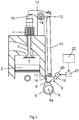
- Fig. 1 depicts part of a cylinder of a combustion engine.
- the cylinder comprises a combustion space 1 defined by a movable piston 2.
- a valve 3 is visible in the cylinder.
- the valve 3 may be an inlet valve to control the supply of air to the combustion space 1, or an exhaust valve to control the evacuation of exhaust gases from the combustion space 1.
- Cylinders have in this case two inlet valves and two exhaust valves, although only one valve is visible in Fig. 1 .
- Each of the valves 3 is connected to a valve spring 4 which endeavours to keep the valve 3 in a closed state.
- the combustion engine in this embodiment is provided with a low-level camshaft 5 which is rotatable at a speed related to the speed of the combustion engine.
- the combustion engine may alternatively be provided with one or more overhead camshafts.
- the camshaft 5 is rotatable about a rotational axis 5a.
- the camshaft 5 is provided with peripheral guide surfaces 6, 7, see Fig. 2 .
- a cam follower 8 is adapted to being in contact with the guide surfaces 6, 7.
- the cam follower 8 comprises a first roller means 9 adapted to being in contact with the first guide surface 6, and a second roller means 10 adapted to being in contact with the second guide surface 7.
- a pushrod 11 fitted substantially vertically has a lower end connected articulatedly to the cam follower 8, and an upper end connected articulatedly to a component 12 which is firmly mounted on a rocker arm 13.
- the upper articulated connection of the pushrod 11 comprises a spherical socket connected to a spherical portion of the component 12.
- the component 12 comprises an adjusting screw and a nut for adjustable fastening of the component 12 to a first end of the rocker arm 13.
- the rocker arm 13 is journalled pivotably at a middle portion about an articulation 14.
- the rocker arm 13 has at a second end, on the opposite side of the articulation 14, a contact surface adapted to being in contact with a valve yoke 15.
- valve yoke 15 depicts the valve yoke 15 as seen from the side.
- the valve yoke 15 is adapted to transmitting control movements to two valves 3 in the cylinder 1.
- the pushrod 11, the component 12, the rocker arm 13 and the valve yoke 15 are components of a motion-transmitting mechanism whose purpose is to convert guiding movements from the cam follower 8 to opening and closing movements of the valves 3.
- the cam follower 8 comprises a first unit 16 which itself comprises the first roller means 9.
- the first unit 16 has at one end an articulated connection 18 with two protruding connecting elements 19 firmly mounted on a rotatable control spindle 20.
- the control spindle 20 is turned to a desired rotational position by means of a schematically depicted power means 21 activated by a control unit 22.
- the power means 21 may be operated electrically, pneumatically or hydraulically.
- the control unit 22 may be a computer unit with suitable software.
- the cam follower 8 comprises also a second unit 17 connected to the pushrod 11.
- the second unit 17 comprises the second roller means 10.
- the first unit 16 comprises a contact portion with a contact surface 23.
- the second unit comprises a contact portion in the form of a contact roller 24 situated vertically above the contact surface 23.
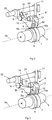
- Fig. 2 depicts the control spindle 20 in a first rotational position.
- the connecting elements 19 of the control spindle 20 keep the first unit 16 in a position in which the first roller means 9 is in contact with the first guide surface 6 at a contact position 9a 1 situated substantially directly above the rotational axis 5a of the camshaft 5.
- Fig. 3 depicts the control spindle 20 in a second rotational position.
- the connecting elements 19 of the control spindle 20 have moved the first unit 16 to a position in which the first roller means 9 is in contact with the first guide surface 6 at a second contact position 9a 2 .
- the second roller means 10 is thus in contact with the second guide surface 7.
- the second roller means 10 is so positioned as to always have contact with the second guide surface 7 at a contact position 10a situated substantially vertically above the rotational axis 5a of the camshaft 5.
- the control spindle 20 may control the inlet valves or the exhaust valves in one, several or all of the cylinders of the combustion engine.
- Fig. 4 depicts the second guide surface 7 in a plane which is perpendicular to the camshaft's rotational axis 5a.
- the second roller means 10 is here positioned on the second guide surface 7 at the contact position 10a.
- a radial axis r 0 extending from the rotational axis 5a to the contact position 10a is marked here.
- the guide surface 7 comprises a protruding portion 7a which has a surface situated at a greater radial distance from the camshaft's rotational axis 5a than the rest of the guide surface 7.
- the protruding portion 7a comprises an initial portion 7a 1 , a maximum portion 7a max and a final portion 7a 2 .
- a radial axis 7r max from the camshaft's rotational centre 5a to the maximum portion 7a max is marked in the diagram.
- the radial axis 7r max will assume varying angles v relative to the radial axis r 0 . This angle we define here as the angle v of the camshaft 5.
- a continuous curve 25 represents the lift d imparted to the valves 3 as a function of the camshaft angle v under the above definition.
- the valve lift d begins when the second roller means 10 comes into contact with the initial portion 7a 1 .
- the camshaft angle at this stage is about -50°, i.e. 310 °.
- the protruding portion 7a effects increasing lifting of the second roller means 10 and hence of the valves 3.
- the valves 3 are at a maximum lift height.
- the angle v of the camshaft 5 at this stage is 0°.
- the protruding portion 7a effects decreasing lifting of the second roller means 10.
- the valves 3 are substantially closed.
- the angle v of the camshaft 5 at this stage is about 50°.
- Fig. 5 depicts the first guide surface 6 in a plane which is perpendicular to the camshaft's rotational axis 5a.
- the first guide surface 6 comprises a protruding portion 6a which has a surface situated at a greater radial distance from the camshaft's rotational axis 5a than the rest of the guide surface 6.
- the protruding portion 6a comprises an initial portion 6a 1 , a maximum portion 6a max and a final portion 6a 2 .
- the first roller means 9 is therefore movable along the guide surface 6 in said plane to various positions of contact 9a with the guide surface 6.
- the first roller means 9 is here represented by a continuous line at the first contact position 9a 1 as in Fig.
- the first contact position 9a 1 is thus situated substantially vertically above the camshaft's rotational axis 5a.
- a radial axis r 1 extending from the rotational axis 5a to the contact position 9a 1 is marked in the diagram.
- a radial axis 6r max extending from the camshaft's rotational centre 5a to the maximum portion 6a max is also marked.
- the first roller means 9 When the first roller means 9 is at the position illustrated by a continuous line in Fig. 5 , it is at a contact position 9a 1 on the guide surface 6 which corresponds to the contact position 10a of the second roller means 10 on the guide surface 7.
- the first roller means 9 undergoes at this contact position 9a 1 a vertical lifting movement similar to the second roller means 10 during operation of the camshaft 5.
- the lift of the first roller means 9 begins when it comes into contact with the initial portion 6a 1 of the protruding portion 6a.
- the protruding portion 6a effects increasing vertical lifting of the first roller means 9.
- the maximum portion 6a max comes into contact with the roller means 9, it reaches a maximum lift height.
- the protruding portion 6a effects decreasing vertical lifting of the first roller means 9.
- the lift has substantially ended.
- the first roller means 9 is at the first contact position 9a 1 , it thus effects lifting which corresponds exactly to the second roller means 10 at corresponding angles v of the camshaft 5.
- the two units 16, 17 of the cam follower 8 effect identical lifts.
- the second unit 17 transmits the lifting movement to the valves 3 via the motion-transmitting mechanism 11-15.
- the contact surface 23 of the first unit 16 is in contact with the contact roller 24 of the second unit 17. Both the first unit 16 and the second unit 17 thus help here to impart a vertical movement upwards which is converted to lifting movements of the valves 3.
- the control unit 22 activates the power means 21, which turns the control spindle 20 to the rotational position depicted in Fig. 3 .
- the connecting elements 19 of the control spindle 20 here move the first unit 16 to a position in which the first roller means 9 makes contact with the first guide surface 6 at the contact position 9a 2 .
- the valve lift begins when the angle v of the camshaft 5 is -50°.
- the second roller means 10 comes into contact with the initial portion 7a 1 .
- the protruding portion 7a lifts the second roller means 10 and the second unit 17.
- the second unit 17 can effect lifting without the first unit 16 being affected.
- the first unit 16 transmits its lifting movement to the valves 3 via the motion-transmitting mechanism 11-15.
- the initial portion 6a 1 of the first guide surface 6 has not yet reached the first roller means 9 because the first roller means 9 has moved to the contact position 9a 2 .
- Only when the camshaft 5 has rotated further and has reached an angle v of about -25° does the initial portion 6a 1 come to the contact position 9a 2 with the first roller means 9.
- the protruding portion 6a effects lifting of the first roller means 9 and the first unit 16.
- the second roller means 10 When the camshaft 5 reaches an angle v of 0°, the second roller means 10 has reached a maximum lift height. During further rotation of the camshaft 5, the second roller means 10 and the second unit 17 begin to drop downwards. A few degrees after the angle 0°, the first roller means 9, which in this situation is thus moving upwards, will reach the same height as the second roller means 10 which is moving downwards. At this stage the contact surface 23 of the first unit comes into contact with the contact roller 24 of the second unit. As it is situated vertically below the contact roller 24, the contact surface 23 ends the downward movement of the second unit 17. At this stage, the second roller means 10 loses contact with the second guide surface 7.
- the contact surface 23 of the first unit 16 keeps the second unit 17 in the almost maximum lifted state until the maximum portion 6a max comes into contact with the roller means 9, which takes place when the angle v is about 25°. Once the maximum portion 6a max has passed the first roller means 9, the first unit 16 and the second unit 17 drop downwards. The result is a closing movement of the valves 3. The closing movement ends when the final portion 6a 2 comes into contact with the first roller means 9, which takes place when the angle v is about 75°.
- valves 3 thus undergo an opening movement defined by the second unit 17 and a closing movement defined by the first unit 16.
- the valves 3 are provided with a lengthened open period related to the angle difference ⁇ v between the contact position 10a of the second roller means and the contact position 9a of the first roller means.
- the angle difference ⁇ v is about 25°. Converted to crankshaft angles, this will be about 50°, since the crankshaft rotates twice as fast as the camshaft 5.
- the broken curve 26 represents the lengthened open period for the valves 3 when the first roller means 9 is at the contact position 9a 2 .
- the curves 27, 28 illustrate two examples of this. It is possible to turn the control spindle 20 so that the first roller means 9 can be put steplessly into any desired contact positions 9a between the contact positions 9a 1 , 9a 2 .
- the closing time of the valves 3 is adjusted.
- the opening time of the valves can be adjusted in a similar way. The simplest way of doing so is by changing the direction of rotation of the camshaft 5.
- the dotted curve 29 in Fig. 6 represents an example in which the valves 3 open at an earlier time.
- Fig. 7 depicts an alternative embodiment in which the two units 9, 10 of the cam follower 8 are movable in a plane which is perpendicular to the camshaft 5.
- the same components 19-22 are here used to adjust the roller means 9, 10 of the units 16, 17 to various contact positions on the respective guide surfaces 6, 7. We therefore give no further description of how this takes place. In this case both the opening time and the closing time for the valves 3 can be adjusted.
Landscapes
- Engineering & Computer Science (AREA)
- Mechanical Engineering (AREA)
- General Engineering & Computer Science (AREA)
- Valve Device For Special Equipments (AREA)
- Valve-Gear Or Valve Arrangements (AREA)
Claims (7)
- Ventilhubvorrichtung für einen Verbrennungsmotor, wobei die Ventilhubvorrichtung eine Nockenwelle (5) mit einer Rotationsachse (5a), eine erste Einheit (16) mit einem ersten Kontaktmittel (9) aufweist, das für den Kontakt mit einer Führungsfläche auf der Nockenwelle (5) eingerichtet ist, wobei die erste Einheit (16) so eingerichtet ist, dass sie angehoben wird, wenn das erste Kontaktmittel (9) mit einem hervorstehenden Abschnitt (6a) der Führungsfläche (6) in Kontakt kommt, und einen Bewegungsübertragungsmechanismus, der dazu eingerichtet ist, die Hubbewegung der Einheit (16) in ein Anheben mindestens eines Ventils (3) des Verbrennungsmotors zu wandeln, wobei die Ventilhubvorrichtung eine Einstellvorrichtung (20 - 22) aufweist, mit der lineare Bewegungen der ersten Einheit (16) und damit des ersten Kontaktmittels (9) in einer Ebene senkrecht zur Rotationsachse (5a) der Nockenwelle zwischen mindestens einer ersten Kontaktposition (9a1) auf der Führungsfläche (6) und einer zweiten Kontaktposition (9a2) auf der Führungsfläche (6) ermöglicht werden,
dadurch gekennzeichnet, dass
die Ventilhubvorrichtung eine zweite Einheit (17) mit einem zweiten Kontaktmittel (10) aufweist, das für den Kontakt mit einer zweiten Führungsfläche (7) auf dem Umfang der Nockenwelle (5) eingerichtet ist, wobei die zweite Einheit (17) so eingerichtet ist, dass sie angehoben wird, wenn das zweite Kontaktmittel mit einem hervorstehenden Abschnitt (7a) der Führungsfläche (7) in Kontakt kommt, wobei die erste und zweite Einheit (16, 17) mit dem Bewegungsübertragungsmechanismus (11 - 15) so verbunden sind, dass die Einheit (16, 17), deren Führungsfläche (6, 7) gerade höher angehoben wird, diesen Hub auf das Ventil (3) überträgt, und dass eine der Einheiten (17) direkt mit dem Bewegungsübertragungsmechanismus (11 - 15) verbunden ist, und dass die andere Einheit (16) einen Kontaktabschnitt (23) aufweist, der für den Eingriff mit einem Kontaktabschnitt (24) der direkt verbundenen Einheit (17) und zum Anheben der Letztgenannten eingerichtet ist, wenn die Führungsfläche (6) der anderen Einheit (16) höher angehoben wird als die direkt verbundene Einheit (17). - Ventilhubvorrichtung nach Anspruch 1, dadurch gekennzeichnet, dass die erste Führungsfläche (6) und die zweite Führungsfläche (7) eine identische Umfangsform aufweisen.
- Ventilhubvorrichtung nach einem der vorigen Ansprüche, dadurch gekennzeichnet, dass die Einstellvorrichtung eine drehbare Steuerspindel (20) aufweist, die parallel zur Nockenwelle verläuft und mit der ersten Einheit (16) über eine Gelenkverbindung (18) verbunden ist, die sich im radialen Abstand zur Steuerspindel (20) befindet.
- Ventilhubvorrichtung nach Anspruch 3, dadurch gekennzeichnet, dass die Einstellvorrichtung eine Antriebseinheit (21) aufweist, die zum Drehen der Spindel (20) in eine gewünschte Rotationsposition eingerichtet ist, und eine Steuereinheit (22), die die Antriebseinheit (21) auf Basis von Informationen bezüglich des Betriebs des Verbrennungsmotors steuert.
- Ventilhubvorrichtung nach einem der vorigen Ansprüche, dadurch gekennzeichnet, dass das Kontaktmittel (10) der zweiten Einheit (17) eine feste Kontaktposition (10a) mit der Führungsfläche (7) hat.
- Ventilhubvorrichtung nach einem der Ansprüche 1 bis 4, dadurch gekennzeichnet, dass die Ventilhubvorrichtung eine zweite Einstellvorrichtung (19 - 22) aufweist, mit der lineare Bewegungen der zweiten Einheit (17) und damit des zweiten Kontaktmittels (10) in einer Ebene senkrecht zur Rotationsachse (5a) der Nockenwelle zwischen mindestens zwei Kontaktpositionen auf der Führungsfläche (7) ermöglicht werden.
- Ventilhubvorrichtung nach einem der vorigen Ansprüche, dadurch gekennzeichnet, dass die Kontaktmittel die Form von Rollenmitteln (9, 10) annehmen, die zum Rollen entlang der Führungsfläche (6, 7) eingerichtet sind.
Applications Claiming Priority (2)
| Application Number | Priority Date | Filing Date | Title |
|---|---|---|---|
| SE1050381A SE534761C2 (sv) | 2010-04-19 | 2010-04-19 | Ventillyftanordning hos en förbränningsmotor |
| PCT/SE2011/050442 WO2011133088A1 (en) | 2010-04-19 | 2011-04-12 | Valve lift device for a combustion engine |
Publications (3)
| Publication Number | Publication Date |
|---|---|
| EP2561191A1 EP2561191A1 (de) | 2013-02-27 |
| EP2561191A4 EP2561191A4 (de) | 2014-12-17 |
| EP2561191B1 true EP2561191B1 (de) | 2017-08-02 |
Family
ID=44834375
Family Applications (1)
| Application Number | Title | Priority Date | Filing Date |
|---|---|---|---|
| EP11772318.9A Active EP2561191B1 (de) | 2010-04-19 | 2011-04-12 | Ventilhebevorrichtung für einen verbrennungsmotor |
Country Status (7)
| Country | Link |
|---|---|
| US (1) | US8770161B2 (de) |
| EP (1) | EP2561191B1 (de) |
| JP (1) | JP5685309B2 (de) |
| CN (1) | CN102859131A (de) |
| RU (1) | RU2513215C1 (de) |
| SE (1) | SE534761C2 (de) |
| WO (1) | WO2011133088A1 (de) |
Families Citing this family (6)
| Publication number | Priority date | Publication date | Assignee | Title |
|---|---|---|---|---|
| JP5907089B2 (ja) * | 2013-02-26 | 2016-04-20 | マツダ株式会社 | エンジンの動弁装置 |
| US9133735B2 (en) * | 2013-03-15 | 2015-09-15 | Kohler Co. | Variable valve timing apparatus and internal combustion engine incorporating the same |
| EP3073070A1 (de) * | 2015-03-25 | 2016-09-28 | Caterpillar Energy Solutions GmbH | Auf einer nockenwelle basierende variable ventilsteuerzeit |
| SE541922C2 (en) * | 2017-03-31 | 2020-01-07 | Scania Cv Ab | Four-stroke Internal Combustion Engine and thereto related Vehicle and Method |
| CN108757081B (zh) * | 2018-05-22 | 2021-06-08 | 大连理工大学 | 一种底置凸轮轴多杆连续可变气门机构 |
| AT522750A1 (de) * | 2019-07-04 | 2021-01-15 | Avl List Gmbh | Variable ventiltriebvorrichtung |
Family Cites Families (23)
| Publication number | Priority date | Publication date | Assignee | Title |
|---|---|---|---|---|
| DE648807C (de) * | 1935-07-30 | 1937-08-09 | Karl Wessel Dipl Ing | Ventilsteuerung fuer Verbrennungsmotoren |
| US2934052A (en) * | 1958-11-17 | 1960-04-26 | Irvin R Longenecker | Valve operating mechanism |
| US4077369A (en) * | 1976-04-21 | 1978-03-07 | Joseph F. Buehner, Trustee | Internal combustion engine valve stroke adjusting device and combination thereof with engine |
| US4205634A (en) * | 1978-02-17 | 1980-06-03 | Tourtelot Edward M Jr | Variable valve timing mechanism |
| US4469056A (en) * | 1983-02-22 | 1984-09-04 | Tourtelot Jr Edward M | Dual follower variable valve timing mechanism |
| JPS62137313A (ja) | 1985-12-09 | 1987-06-20 | Masaharu Fukue | 曳航式海底土質判別装置 |
| JPS62137313U (de) * | 1986-02-22 | 1987-08-29 | ||
| JPS634313A (ja) | 1986-06-24 | 1988-01-09 | Hiruta Kogyo Kk | ブレ−キ等のペダル位置調整装置 |
| JPS634313U (de) * | 1986-06-27 | 1988-01-12 | ||
| EP0262256A1 (de) | 1986-10-03 | 1988-04-06 | Werner Dipl.-Ing. Emmel | Nockenwelle eines Hubkolbenmotors |
| JPH02123215A (ja) * | 1988-10-31 | 1990-05-10 | Suzuki Motor Co Ltd | 四サイクルエンジンのバルブタイミング可変装置 |
| US5253621A (en) * | 1992-08-14 | 1993-10-19 | Group Lotus Plc | Valve control means |
| GB9021270D0 (en) * | 1990-10-01 | 1990-11-14 | Mitchell Stephen W | Improvements in or relating to driving connections between two rotatable bodies |
| US6491008B1 (en) * | 2001-10-18 | 2002-12-10 | Ford Global Technologies, Inc. | Variable valve timing adjustable roller rocker arm assembly |
| US7007650B2 (en) * | 2003-10-31 | 2006-03-07 | Caterpillar Inc | Engine valve actuation system |
| WO2005061864A1 (ja) * | 2003-12-24 | 2005-07-07 | Honda Motor Co., Ltd. | 内燃機関のバルブリフト可変装置 |
| JPWO2005075798A1 (ja) * | 2004-02-06 | 2007-08-02 | 株式会社ミクニ | エンジンの可変動弁装置 |
| EP1785598B1 (de) * | 2004-08-31 | 2010-12-15 | Toyota Jidosha Kabushiki Kaisha | Verstellbare ventilsteuerung |
| DE112006002254B4 (de) * | 2005-09-27 | 2013-01-31 | Toyota Jidosha K.K. | Verstellbare Ventilbetätigungsvorrichtung und Verfahren zum Einstellen eines Ventilöffnungsbetrags |
| US7506624B2 (en) * | 2006-02-28 | 2009-03-24 | Perkins Engines Company Limited | Variable engine valve actuation system |
| FR2899276A1 (fr) * | 2006-03-28 | 2007-10-05 | Renault Sas | Dispositif de commande de levee variable de soupapes |
| EP2025888A1 (de) * | 2007-08-06 | 2009-02-18 | Iveco S.p.A. | Gerät zur Betätigung der Dekompressions-Motorbremse in einem mit hydraulischen Nocken ausgestatteten Verbrennungsmotor |
| CN101403326A (zh) * | 2008-06-16 | 2009-04-08 | 奇瑞汽车股份有限公司 | 一种内燃机可变气门升程机构 |
-
2010
- 2010-04-19 SE SE1050381A patent/SE534761C2/sv unknown
-
2011
- 2011-04-12 US US13/641,609 patent/US8770161B2/en not_active Expired - Fee Related
- 2011-04-12 RU RU2012148904/06A patent/RU2513215C1/ru not_active IP Right Cessation
- 2011-04-12 CN CN2011800196736A patent/CN102859131A/zh active Pending
- 2011-04-12 WO PCT/SE2011/050442 patent/WO2011133088A1/en not_active Ceased
- 2011-04-12 EP EP11772318.9A patent/EP2561191B1/de active Active
- 2011-04-12 JP JP2013506111A patent/JP5685309B2/ja not_active Expired - Fee Related
Also Published As
| Publication number | Publication date |
|---|---|
| CN102859131A (zh) | 2013-01-02 |
| US8770161B2 (en) | 2014-07-08 |
| JP2013525673A (ja) | 2013-06-20 |
| US20130032109A1 (en) | 2013-02-07 |
| EP2561191A1 (de) | 2013-02-27 |
| EP2561191A4 (de) | 2014-12-17 |
| WO2011133088A1 (en) | 2011-10-27 |
| SE1050381A1 (sv) | 2011-10-20 |
| JP5685309B2 (ja) | 2015-03-18 |
| RU2513215C1 (ru) | 2014-04-20 |
| SE534761C2 (sv) | 2011-12-13 |
Similar Documents
| Publication | Publication Date | Title |
|---|---|---|
| US5592906A (en) | Method and device for variable valve control of an internal combustion engine | |
| EP2561191B1 (de) | Ventilhebevorrichtung für einen verbrennungsmotor | |
| US6041746A (en) | Variable valve actuation apparatus | |
| US20080078346A1 (en) | System for selectively varying engine valve open duration | |
| US6659053B1 (en) | Fully variable valve train | |
| US6382151B2 (en) | Ring gear variable valve train device | |
| EP1167705B1 (de) | Reibungsarme variable Ventilbetätigungsvorrichtung | |
| US7600496B2 (en) | Valve operating apparatus for internal combustion engine | |
| JP2004301058A (ja) | エンジンの可変動弁装置 | |
| US20160146073A1 (en) | Variable valve gear | |
| JP2005282573A (ja) | 可変リフト装置 | |
| KR101317140B1 (ko) | 무단 가변 밸브 리프트 장치 | |
| CN210068258U (zh) | 一种连续可变气门升程装置 | |
| KR100667394B1 (ko) | 엔진의 연속 가변 밸브 리프트 장치 | |
| EP2157292A1 (de) | Ventilgetriebeanordnung für einen Verbrennungsmotor | |
| CN102797532A (zh) | 可变时间截面控制装置 | |
| JP4622431B2 (ja) | エンジンの可変動弁装置 | |
| US20060091344A1 (en) | Variable valve gear | |
| JPH10121925A (ja) | 内燃機関用バルブ駆動装置 | |
| US4495902A (en) | Mechanism for variably controlling an internal combustion engine valve | |
| US20030101951A1 (en) | Extended duration cam lobe for variable valve actuation mechanism | |
| GB2478559A (en) | Timing mechanism to provide variable valve timing in an internal combustion engine | |
| EP1426570A2 (de) | Mechanismus zur variablen Ventilsteuerung mit geringer Reibung | |
| JP2006207591A (ja) | 内燃機関のシリンダバルブ作動システム | |
| KR100921801B1 (ko) | 무단 가변 밸브 리프트 장치 |
Legal Events
| Date | Code | Title | Description |
|---|---|---|---|
| PUAI | Public reference made under article 153(3) epc to a published international application that has entered the european phase |
Free format text: ORIGINAL CODE: 0009012 |
|
| 17P | Request for examination filed |
Effective date: 20121119 |
|
| AK | Designated contracting states |
Kind code of ref document: A1 Designated state(s): AL AT BE BG CH CY CZ DE DK EE ES FI FR GB GR HR HU IE IS IT LI LT LU LV MC MK MT NL NO PL PT RO RS SE SI SK SM TR |
|
| DAX | Request for extension of the european patent (deleted) | ||
| A4 | Supplementary search report drawn up and despatched |
Effective date: 20141114 |
|
| RIC1 | Information provided on ipc code assigned before grant |
Ipc: F01L 13/00 20060101AFI20141110BHEP Ipc: F01L 13/08 20060101ALI20141110BHEP |
|
| GRAP | Despatch of communication of intention to grant a patent |
Free format text: ORIGINAL CODE: EPIDOSNIGR1 |
|
| INTG | Intention to grant announced |
Effective date: 20170306 |
|
| GRAS | Grant fee paid |
Free format text: ORIGINAL CODE: EPIDOSNIGR3 |
|
| GRAA | (expected) grant |
Free format text: ORIGINAL CODE: 0009210 |
|
| AK | Designated contracting states |
Kind code of ref document: B1 Designated state(s): AL AT BE BG CH CY CZ DE DK EE ES FI FR GB GR HR HU IE IS IT LI LT LU LV MC MK MT NL NO PL PT RO RS SE SI SK SM TR |
|
| REG | Reference to a national code |
Ref country code: GB Ref legal event code: FG4D |
|
| REG | Reference to a national code |
Ref country code: CH Ref legal event code: EP Ref country code: AT Ref legal event code: REF Ref document number: 914730 Country of ref document: AT Kind code of ref document: T Effective date: 20170815 |
|
| REG | Reference to a national code |
Ref country code: IE Ref legal event code: FG4D |
|
| REG | Reference to a national code |
Ref country code: DE Ref legal event code: R096 Ref document number: 602011040185 Country of ref document: DE |
|
| REG | Reference to a national code |
Ref country code: NL Ref legal event code: MP Effective date: 20170802 |
|
| REG | Reference to a national code |
Ref country code: AT Ref legal event code: MK05 Ref document number: 914730 Country of ref document: AT Kind code of ref document: T Effective date: 20170802 |
|
| REG | Reference to a national code |
Ref country code: LT Ref legal event code: MG4D |
|
| PG25 | Lapsed in a contracting state [announced via postgrant information from national office to epo] |
Ref country code: NO Free format text: LAPSE BECAUSE OF FAILURE TO SUBMIT A TRANSLATION OF THE DESCRIPTION OR TO PAY THE FEE WITHIN THE PRESCRIBED TIME-LIMIT Effective date: 20171102 Ref country code: NL Free format text: LAPSE BECAUSE OF FAILURE TO SUBMIT A TRANSLATION OF THE DESCRIPTION OR TO PAY THE FEE WITHIN THE PRESCRIBED TIME-LIMIT Effective date: 20170802 Ref country code: FI Free format text: LAPSE BECAUSE OF FAILURE TO SUBMIT A TRANSLATION OF THE DESCRIPTION OR TO PAY THE FEE WITHIN THE PRESCRIBED TIME-LIMIT Effective date: 20170802 Ref country code: SE Free format text: LAPSE BECAUSE OF FAILURE TO SUBMIT A TRANSLATION OF THE DESCRIPTION OR TO PAY THE FEE WITHIN THE PRESCRIBED TIME-LIMIT Effective date: 20170802 Ref country code: LT Free format text: LAPSE BECAUSE OF FAILURE TO SUBMIT A TRANSLATION OF THE DESCRIPTION OR TO PAY THE FEE WITHIN THE PRESCRIBED TIME-LIMIT Effective date: 20170802 Ref country code: HR Free format text: LAPSE BECAUSE OF FAILURE TO SUBMIT A TRANSLATION OF THE DESCRIPTION OR TO PAY THE FEE WITHIN THE PRESCRIBED TIME-LIMIT Effective date: 20170802 Ref country code: AT Free format text: LAPSE BECAUSE OF FAILURE TO SUBMIT A TRANSLATION OF THE DESCRIPTION OR TO PAY THE FEE WITHIN THE PRESCRIBED TIME-LIMIT Effective date: 20170802 |
|
| PG25 | Lapsed in a contracting state [announced via postgrant information from national office to epo] |
Ref country code: RS Free format text: LAPSE BECAUSE OF FAILURE TO SUBMIT A TRANSLATION OF THE DESCRIPTION OR TO PAY THE FEE WITHIN THE PRESCRIBED TIME-LIMIT Effective date: 20170802 Ref country code: PL Free format text: LAPSE BECAUSE OF FAILURE TO SUBMIT A TRANSLATION OF THE DESCRIPTION OR TO PAY THE FEE WITHIN THE PRESCRIBED TIME-LIMIT Effective date: 20170802 Ref country code: BG Free format text: LAPSE BECAUSE OF FAILURE TO SUBMIT A TRANSLATION OF THE DESCRIPTION OR TO PAY THE FEE WITHIN THE PRESCRIBED TIME-LIMIT Effective date: 20171102 Ref country code: ES Free format text: LAPSE BECAUSE OF FAILURE TO SUBMIT A TRANSLATION OF THE DESCRIPTION OR TO PAY THE FEE WITHIN THE PRESCRIBED TIME-LIMIT Effective date: 20170802 Ref country code: GR Free format text: LAPSE BECAUSE OF FAILURE TO SUBMIT A TRANSLATION OF THE DESCRIPTION OR TO PAY THE FEE WITHIN THE PRESCRIBED TIME-LIMIT Effective date: 20171103 Ref country code: LV Free format text: LAPSE BECAUSE OF FAILURE TO SUBMIT A TRANSLATION OF THE DESCRIPTION OR TO PAY THE FEE WITHIN THE PRESCRIBED TIME-LIMIT Effective date: 20170802 Ref country code: IS Free format text: LAPSE BECAUSE OF FAILURE TO SUBMIT A TRANSLATION OF THE DESCRIPTION OR TO PAY THE FEE WITHIN THE PRESCRIBED TIME-LIMIT Effective date: 20171202 |
|
| PG25 | Lapsed in a contracting state [announced via postgrant information from national office to epo] |
Ref country code: CZ Free format text: LAPSE BECAUSE OF FAILURE TO SUBMIT A TRANSLATION OF THE DESCRIPTION OR TO PAY THE FEE WITHIN THE PRESCRIBED TIME-LIMIT Effective date: 20170802 Ref country code: DK Free format text: LAPSE BECAUSE OF FAILURE TO SUBMIT A TRANSLATION OF THE DESCRIPTION OR TO PAY THE FEE WITHIN THE PRESCRIBED TIME-LIMIT Effective date: 20170802 Ref country code: RO Free format text: LAPSE BECAUSE OF FAILURE TO SUBMIT A TRANSLATION OF THE DESCRIPTION OR TO PAY THE FEE WITHIN THE PRESCRIBED TIME-LIMIT Effective date: 20170802 |
|
| REG | Reference to a national code |
Ref country code: DE Ref legal event code: R097 Ref document number: 602011040185 Country of ref document: DE |
|
| PG25 | Lapsed in a contracting state [announced via postgrant information from national office to epo] |
Ref country code: SM Free format text: LAPSE BECAUSE OF FAILURE TO SUBMIT A TRANSLATION OF THE DESCRIPTION OR TO PAY THE FEE WITHIN THE PRESCRIBED TIME-LIMIT Effective date: 20170802 Ref country code: IT Free format text: LAPSE BECAUSE OF FAILURE TO SUBMIT A TRANSLATION OF THE DESCRIPTION OR TO PAY THE FEE WITHIN THE PRESCRIBED TIME-LIMIT Effective date: 20170802 Ref country code: EE Free format text: LAPSE BECAUSE OF FAILURE TO SUBMIT A TRANSLATION OF THE DESCRIPTION OR TO PAY THE FEE WITHIN THE PRESCRIBED TIME-LIMIT Effective date: 20170802 Ref country code: SK Free format text: LAPSE BECAUSE OF FAILURE TO SUBMIT A TRANSLATION OF THE DESCRIPTION OR TO PAY THE FEE WITHIN THE PRESCRIBED TIME-LIMIT Effective date: 20170802 |
|
| PLBE | No opposition filed within time limit |
Free format text: ORIGINAL CODE: 0009261 |
|
| STAA | Information on the status of an ep patent application or granted ep patent |
Free format text: STATUS: NO OPPOSITION FILED WITHIN TIME LIMIT |
|
| 26N | No opposition filed |
Effective date: 20180503 |
|
| PG25 | Lapsed in a contracting state [announced via postgrant information from national office to epo] |
Ref country code: SI Free format text: LAPSE BECAUSE OF FAILURE TO SUBMIT A TRANSLATION OF THE DESCRIPTION OR TO PAY THE FEE WITHIN THE PRESCRIBED TIME-LIMIT Effective date: 20170802 |
|
| PG25 | Lapsed in a contracting state [announced via postgrant information from national office to epo] |
Ref country code: MC Free format text: LAPSE BECAUSE OF FAILURE TO SUBMIT A TRANSLATION OF THE DESCRIPTION OR TO PAY THE FEE WITHIN THE PRESCRIBED TIME-LIMIT Effective date: 20170802 |
|
| REG | Reference to a national code |
Ref country code: CH Ref legal event code: PL |
|
| REG | Reference to a national code |
Ref country code: BE Ref legal event code: MM Effective date: 20180430 |
|
| GBPC | Gb: european patent ceased through non-payment of renewal fee |
Effective date: 20180412 |
|
| REG | Reference to a national code |
Ref country code: IE Ref legal event code: MM4A |
|
| PG25 | Lapsed in a contracting state [announced via postgrant information from national office to epo] |
Ref country code: LU Free format text: LAPSE BECAUSE OF NON-PAYMENT OF DUE FEES Effective date: 20180412 |
|
| PG25 | Lapsed in a contracting state [announced via postgrant information from national office to epo] |
Ref country code: LI Free format text: LAPSE BECAUSE OF NON-PAYMENT OF DUE FEES Effective date: 20180430 Ref country code: CH Free format text: LAPSE BECAUSE OF NON-PAYMENT OF DUE FEES Effective date: 20180430 Ref country code: BE Free format text: LAPSE BECAUSE OF NON-PAYMENT OF DUE FEES Effective date: 20180430 Ref country code: GB Free format text: LAPSE BECAUSE OF NON-PAYMENT OF DUE FEES Effective date: 20180412 |
|
| PG25 | Lapsed in a contracting state [announced via postgrant information from national office to epo] |
Ref country code: IE Free format text: LAPSE BECAUSE OF NON-PAYMENT OF DUE FEES Effective date: 20180412 Ref country code: FR Free format text: LAPSE BECAUSE OF NON-PAYMENT OF DUE FEES Effective date: 20180430 |
|
| PG25 | Lapsed in a contracting state [announced via postgrant information from national office to epo] |
Ref country code: MT Free format text: LAPSE BECAUSE OF NON-PAYMENT OF DUE FEES Effective date: 20180412 |
|
| PG25 | Lapsed in a contracting state [announced via postgrant information from national office to epo] |
Ref country code: TR Free format text: LAPSE BECAUSE OF FAILURE TO SUBMIT A TRANSLATION OF THE DESCRIPTION OR TO PAY THE FEE WITHIN THE PRESCRIBED TIME-LIMIT Effective date: 20170802 |
|
| PG25 | Lapsed in a contracting state [announced via postgrant information from national office to epo] |
Ref country code: PT Free format text: LAPSE BECAUSE OF FAILURE TO SUBMIT A TRANSLATION OF THE DESCRIPTION OR TO PAY THE FEE WITHIN THE PRESCRIBED TIME-LIMIT Effective date: 20170802 Ref country code: HU Free format text: LAPSE BECAUSE OF FAILURE TO SUBMIT A TRANSLATION OF THE DESCRIPTION OR TO PAY THE FEE WITHIN THE PRESCRIBED TIME-LIMIT; INVALID AB INITIO Effective date: 20110412 |
|
| PG25 | Lapsed in a contracting state [announced via postgrant information from national office to epo] |
Ref country code: CY Free format text: LAPSE BECAUSE OF FAILURE TO SUBMIT A TRANSLATION OF THE DESCRIPTION OR TO PAY THE FEE WITHIN THE PRESCRIBED TIME-LIMIT Effective date: 20170802 Ref country code: MK Free format text: LAPSE BECAUSE OF NON-PAYMENT OF DUE FEES Effective date: 20170802 |
|
| PG25 | Lapsed in a contracting state [announced via postgrant information from national office to epo] |
Ref country code: AL Free format text: LAPSE BECAUSE OF FAILURE TO SUBMIT A TRANSLATION OF THE DESCRIPTION OR TO PAY THE FEE WITHIN THE PRESCRIBED TIME-LIMIT Effective date: 20170802 |
|
| P01 | Opt-out of the competence of the unified patent court (upc) registered |
Effective date: 20230518 |
|
| PGFP | Annual fee paid to national office [announced via postgrant information from national office to epo] |
Ref country code: DE Payment date: 20250305 Year of fee payment: 15 |